Introduction Chairperson: K. Matsumoto (JAXA)
Japan’s Materials Space Exposure Experiments before SM/MPAC&SEED M. Suzuki, H. Shimamura, K. Imagawa (JAXA)
SM/MPAC&SEED Experiment Overview
Y. Kimoto, J. Ishizawa, E. Miyazaki, M. Suzuki (JAXA)
Space Environment of SM/MPAC&SEED Chairperson: F. Urayama (SED)
Post Retrieval Analyses of Space Environment Monitoring Samples: Radiation Effects, UV, and Atomic Oxygen Fluence
Y. Kimoto, K. Yano, J. Ishizawa, E. Miyazaki (JAXA)
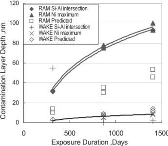
Induced Contamination Predictions for JAXA’s Micro-Particles Capturer and Space Environment Exposure Devices
C. Steagall, K. Smith, A. Huang, C. Soares, and R. Mikatarian (The Boeing Company)
Contamination Effect on SM/MPAC&SEED Experiment N. Baba (JAMSS), Y. Kimoto (JAXA)
New Polymeric Materials Chairperson: T. Nakamura (Hokkaido University)
Thermal and environmental stability of polymeric materials - New generation, novel asymmetric aromatic polyimides - R. Yokota (JAXA)
1
5
11
19
27
35
Y. Kitazawa (IHI Corporation), A. Fujiwara (Kansai University), T. Kadono (Nagoya University), T. Noguchi (Ibaraki University), R. Yamanaka, Y. Kimoto, M. Suzuki (JAXA)
Initial Investigation of Silica Aerogel Equipped on SM/MPAC & SEED Recovered from the ISS in 2002, 2004, and 2005
T. Noguchi (Ibaraki University), T. Nakamura (Kyushu University), Y. Kitazawa (IHI Corporation), R. Yamanaka, Y. Kimoto, M. Suzuki (JAXA)
Materials in Space -1 Chairperson: J. Ishizawa (JAXA)
Influence on Polymer Matrix Composite Exposed to Space Environment Y. Arakawa (Fuji Heavy Industries LTD.)
Effects of LEO Environment on Mechanical Properties of PEEK Films under Tensile Stress T. Nakamura and O. Fujita (Hokkaido University)
Effects of LEO Environment on Mechanical Properties of Polyimide Films under Tensile Stress
H. Shimamura (JAXA)
Materials in Space -2 Chairperson: M. Tagawa (Kobe University)
NASA Glenn Research Center’s Materials International Space Station Experiments (MISSE 1-7)
K. K. de Groh (NASA Glenn Research Center), B. A. Banks (Consultant, Alphaport, Inc.), J. A.
Dever, D. A. Jaworske, S. K. Miller (NASA Glenn Research Center)
59
67
73
81
91
Evaluation of MoS2 Bonded Film Degradation on ISS SM-SEED Experiment M. Akiyama (IHI Aerospace), M. Tagawa (Kobe University), K. Matsumoto (JAXA)
Evaluation of Solid Lubricative Coatings after Space Environment Exposure Test M. Tosa, A. Kasahara, M. Goto (National Institute for Materials Science)
Materials in Space -4 Chairperson: M. Iwata (Kyushu Institute of Technology)
SM/SEED Experiments of Carbide and Nitride Ceramics for Three Years O. Odawara (Tokyo Institute of Technology)
Material Aging of Siloxane Coated Polyimide Film and Silicone Based White Paint on SM/SEED Exposure Experiments
J. Ishizawa (JAXA)
Evaluation of F-OSR Exposed to Space on SM/SEED Experiment E. Miyazaki, J. Ishizawa, H. Shimamura (JAXA)
Evaluation of Silicone Potting Compound and Silicone Adhesive Exposed to Space on SM/SEED Experiment
E. Miyazaki, K. Mori, J. Ishizawa, H. Shimamura (JAXA)
On-going & Future plan Chairperson: M. Tosa (National Institute for Materials Science)
MEDET in-Flight Experiment: Description and First Results
V. Inguimbert, S. Duzellier, JM Siguier (ONERA), A. Tighe, M. V. Eesbeek (ESA/ESTEC)
127
131
135
139
149
155
161
Future Space Exposure Experiment beyond 2011 -Its Problems and New Challenges
M. Tagawa (Kobe University)
171
ISS and MPAC&SEED from STS-110 flight (April, 2002)
(c)Roskosmos/RSC-Energia
Copy of MCC display in Moscow (March, 2004)
(c)Roskosmos/RSC-Energia (c)Roskosmos/RSC-Energia
Participants photo of International Symposium on “SM/MPAC&SEED Experim
JAPAN. In the Symposium, 22 papers are presented, including three key-note presentations.
The SM/MPAC&SEED, consisted of three identical sample units, was launched to ISS (International Space Station) by Progress on August 2001, and attached on the exterior surface of the Russian Service Module(SM) on October 2001. Each sample unit contained various materials to capture micro-particles and to examine the effects of space environment effects.
The first unit was retrieved into inside the ISS by EVA (Extra-Vehicular Activity) on August 2002, and returned to the Earth on November 2002. The second unit was retrieved on February 2004, and returned to the Earth on April 2004. The final unit was retrieved on August 2005, and returned to the Earth on October 2005. All the units were successfully retrieved, and the analyses of the samples have been conducted. The unique feature of this experiment is that the identical samples were retrieved changing the space exposure duration.
Symposia on SM/MPAC&SEED experiment have been held on March 2004, and on February 2006 for first and second retrieved samples, respectively. In the present, final Symposium, summarizing results of the SM/MPAC&SEED experiment for all the retrieved samples were reported.
Analysis results are sometimes confusing and/or contradicted each other in some cases. One cause of this is that the material degradation process is complex phenomena, in which numerous factors are involved, such as atomic oxygen, ultraviolet rays, radiation, contaminants and so on. To understand the space environment effects exactly based on the limited data, exchange of information and experiences, and discussions among the related researchers are mandatory. In this Symposium, the discussions among the participants were active, and in-depth. I believe the Symposium contributed for the advances in this disciplines.
March, 2008
JAXA, Institute of Aerospace Technology Electronic, Mechanical Components and Materials Group
Mineo SUZUKI
Mineo SUZUKI 1, Hiroyuki SHIMAMURA 1 and Kichiro IMAGAWA 2
1 Institute of Aerospace Technology, Japan Aerospace Exploration Agency, Tsukuba, Ibaraki 305-8505, Japan
2 Human Space Systems and Utilization Mission Directorate, Japan Aerospace Exploration Agency, Tsukuba, Ibaraki 305-8505, Japan
Overview of Japan’s materials space exposure experiments before SM/MPAC&SEED is presented. They are EOIM-3, EFFU and ESEM. EOIM-3 and ESEM experiments were carried out on board the Space Shuttle, while EFFU was mounted on SFU free flyer. In these experiments, there were many valuable findings, but contradictory phenomena were sometimes observed for similar materials, possibly due to the differences of the space environment and the specimens experiment-by-experiment. These experiences greatly contributed to planning and successful completion of SM/MPAC&SEED experiment.
Keywords: Materials space exposure experiments, EOIM-3, EFFU, ESEM 1. Introduction
Space is harsh environment for materials. Materials might be degraded by space environments such as radiation, ultraviolet (UV) rays, atomic oxygen (AO), thermal cycling and so on. Thus the effects of these environment factors on various materials have been examined in simulated ground-based tests, as well as space exposure experiments.
Space Shuttle opened new era for materials space exposure experiments. The exposed samples can be easily retrieved and detailed analysis is possible on ground.
Meanwhile, Space Shuttle demonstrated necessity of materials space exposure experiment: serious AO effect was recognized in Low Earth Orbit (LEO) in early flights (e.g. Ag was blackened by AO during 1 week exposure). Later, combined effect of AO and UV became clear on some materials, but ground simulation technique was not yet established. ISS (International Space Station) program urged evaluation of materials degradation by long duration exposure to LEO environment. Thus a number of materials space exposure experiments were carried out, including EOIM (Evaluation of Oxygen Interaction with Materials), LDEF (Long Duration Exposure Facility) and EURECAEuropean Retrievable Carrier).
After construction of early phase of ISS, materials space exposure experiments were carried out almost on the ISS, such as MISSE (Materials International Space Station Experiment), and SM/MPAC&SEED (Service Module/ Micro -Particles Capturer and Space Environment Exposure Device). ISS is suitable for long duration experiments.
Japan had conducted three materials space exposure experiments before SM/MPAC&SEED experiment. They are:
- EOIM-3 (Evaluation of Oxygen Interaction with Materials - 3)
- EFFU (Exposed Facility Flyer Unit) on SFU (Space Flyer Unit)
- ESEM (Evaluation of Space Environment and Effects on Materials) on MFD (Manipulator Flight Demonstration)
2. EOIM-3
Launched on STS-46 (Atlantis) on July 31, 1992, EOIM-3 pallet containing 46 Japan’s samples (26 kinds) were exposed to the space environment, and returned to the Earth on Aug.8, 1992. EOIM-3 was Japan’s first materials space exposure experiment. EOIM was NASA’s materials space exposure project [1], and Japan participated in the NASA project. The objective of Japan’s experiment was to confirm the phenomena occurred on the material surface induced by space exposure, and to pursue the degradation mechanisms, mainly due to atomic oxygen.
The overview of EOIM-3 experiment is shown in Fig.1.
The samples were typical materials already used for Japanese satellites, and to be used for JEM (Japanese Experiment Module) of ISS. The exposed samples were:
- Thermal control film & paint : 11 kinds, 19 samples - Structural materials: 3 kinds, 8 samples
- Insulating materials: 4 kinds, 7 samples - Adhesives: 3 kinds, 5 samples - Optical materials: 5 kinds, 7 samples
The estimated environments for about 1week flight were:
- AO Fluence
Thermospheric model: 2.0-2.21020 atoms/cm2 Kapton erosion: 2.3-2.51020 atoms/cm2 Mass spectrometer: 2.2±0.41020 atoms/cm2
- UV Fluence
25 ESH (Equivalent Solar Hours) - Temperature
5͠-20͠ during exposure period - Contamination
2 nm thickness silicone
Retrieved samples were examined by using surface analysis techniques such as SEM(Scanning Electron Microscope), XPS(X-ray Photoelectron Spectroscopy), AES(Auger Electron Spectroscopy), FTIR(Fourier Transform InfraRed spectroscopy), SIMS(Secondary Ion Mass Spectrometry), focusing on the effect of AO. AO erosion yields
the other EOIM experiments, and with that caused by ground-based atomic oxygen (AO) irradiation. The importance of AO effects on materials was recognized.
The degradation mechanisms were also pursued. But available data were too limited to elucidate the mechanisms. In addition, some samples showed different results from the former experiments. The major findings of the experiment are reported in ref. [2].
3. EFFU
EFFU was attached to exterior of SFU, and launched on March, 1995 by H-2 rocket. After 10 months flight in 482 km orbit, SFU was retrieved into STS-72 (Endeavour) on January, 1996. EFFU was Japan’s first long duration materials space exposure experiment. The major purpose of the experiment was to confirm the adequacy of materials design for JEM-EF (Japanese Experiment Module - Exposed Facility) to be jointed to ISS. The overview of EFFU experiment is shown in Fig.2.
EFFU carried following 22 kinds of samples.
- Solid lubricant: 7 kinds - CFRP: 3 kinds - Cover glass: 2 kinds - Anodized aluminum: 4 kinds - Thermal control film & paint :5 kinds - Insulating materials: 1 kind
Unique samples were solid lubricant films. JEM-EF has moving mechanical components, which will be partly exposed directly to space environment.
Accumulated fluxes of UV and AO for about 10 month’s exposure were estimated by using monitoring materials, as follows:
- AO Fluence
+Z: 2.51019 atoms/cm2 -X: 4.71019 atoms/cm2
- UV Fluence +Z: very small
Passive Sample Carriers
Japanese Tray (46 samples) STS-46 (Atlantis),
Launched on July 31, 1992, Returned on Aug.8, 1992
Fig.1 Overview of EOIM-3 experiment
Materials pallet
Materials pallet
PTFE in -cloth). The degradation was within the design margin, thus the soundness of JEM materials design was confirmed.
The exposed solid lubricant film showed longer wear life, possibly due to hardening of the organic binder material by UV.
It was pointed out, however, that further hardening may cause rupture of the film. Contamination of SiOx was identified. It is recognized that effects of the contamination should be included to evaluate the effect of actual space environment on materials.
This experiment gave the first insight of long-term space exposure effect on materials for Japanese researchers. The major findings of the experiment are reported in refs. [3][4].
4. ESEM
ESEM pallet containing 29 kinds of samples was attached on the support structure of MFD, and launched on STS-85 (Discovery) on Aug.7, 1997. After about 12 day’s exposure, ESEM was returned to the Earth on Aug.19, 1997. ESEM was a follow-on experiment to confirm soundness of JEM materials design. Figure 3 shows the location of ESEM pallet and the appearance of ESEM sample trays.
The exposed samples were:
- Solid lubricant: 7 kinds - Solar cell: 2 kinds - Cover glass: 4 kinds - Adhesives: 3 kinds
- Thermal control film & paint :9 kinds - Insulating materials: 1 kind
- Inter-connector materials: 3 kinds
In addition, 6 kinds of samples were attached on the sample tray for the evaluation of the exposed environment such as radiation, atomic oxygen, and ultra violet flux.
Accumulated fluxes of UV and AO for about 12 day’s exposure were estimated as follows:
- AO Fluence
3.0 – 9.71019 atoms/cm2 (depended on the location) - UV Fluence
1.8 -2.7 ESD (depended on the location)
Analysis of the retrieved samples gave similar results with the former space exposure experiments. In a follow-up experiment of solid lubricant films, binder itself was exposed.
The binder was eroded away, but never hardened. The effect of space environment might be different between composite materials and their constituents. Contamination of organic materials as well as SiOx was detected.
Detailed analysis results of the retrieved samples are summarized in ref. [5].
5. Concluding remarks
In EOIM-3, SFU/EFFU, and MFD/ESEM experiments, there are many valuable findings. However, the effect of space environment on materials and the degradation mechanism are
difference of space environment experiment-by-experiment (orbit, attitude of the sample tray and duration). Apparently further experiments are needed to fully understand the effect of space environment on materials.
In SM/MPAC&SEED experiment the same 3 sample sets were exposed to the same space environment, but different exposure duration (about 1, 2, and 3 years), to grasp the degradation process more precisely. This method is effective to deduce the degradation process by the space environment.
The detailed experimental results of SM/MPAC&SEED are reported in other papers in this proceedings.
ISS is now being utilized for materials space exposure experiments such as MISSE, EuTEF/MEDET(European Technology Exposure Facility/ Material Exposure and Degradation ExperimenT) and, in the near future, JEM /MPAC&SEED. However, opportunity of materials space exposure experiment is still limited. In these circumstances, cooperation and information exchange among researchers and engineers related to space environment effect on materials will be mandatory.
Fig.3 ESEM sample trays and mounted location
Contractor report, Toshiba SPD15-K93078 (1993). (in Japanese)
[3] M. Takei, Y. Torii et al.: Space environmental effects on space exposure materials of EFFU, Proc. 47th IAC, IAF-96-1.5.01 (1996)
[5] Evaluation and Analysis of Parts and Materials installed on MFD-ESEM, NASDA Technical Memorandum NASDA-TMR-000011 (2001)
Yugo Kimoto, Junichiro Ishizawa, Eiji Miyazaki, Mineo Suzuki Institute of Aerospace Technology, Japan Aerospace Exploration Agency,
Tsukuba, Ibaraki 305-8505, Japan
A space materials exposure experiment was performed on the International Space Station (ISS) using the Micro-Particles Capturer and Space Environment Exposure Device (MPAC&SEED) developed by the Japan Aerospace Exploration Agency (JAXA). The experiment was executed on the exterior of the Russian Service Module (SM) of the ISS. The SM/MPAC&SEED consists of the MPAC, which captures space debris, and SEED, which exposes polymeric materials, paint, adhesives, bearings, and compound materials. Three identical MPAC&SEED units were launched on 21 August 2001. The three units were retrieved individually after exposure of 315 days (about 10 months), 865 days (about 28 months), and 1403 days (about 46 months). This paper presents an overview of the SM/MPAC&SEED project and experiment.
Keywords: SM/MPAC&SEED, ISS Service Module 1. Introduction
Space environment effects on materials are very severe and complex because orbital environments include factors such as high-energy radiation particles, atomic oxygen (AO), micro-level particles, and UV irradiation. In addition, surface degradation associated with contamination can negatively impact optics performance. The space environment and data related to its effects are therefore very important for spacecraft design. The National Space Development Agency of Japan (NASDA), the forerunner of the Japan Aerospace Exploration Agency (JAXA), implemented the space materials exposure experiment on the space shuttle and the ISS. The Russian Service Module (SM)/ Micro-Particle Capturer and Space Environment Exposure Device (MPAC&SEED) experiments were executed on the exterior of the SM of the ISS.
2. History of space materials exposure experiments
Since the first space shuttle launch in the 1980s, research of the characteristics of materials in space environments has shifted from evaluation of data collected by telemetry to that of materials exposed in a real space environment and returned to the ground. NASA implemented space materials exposure experiments using both the space shuttle cargo bay and spacecraft launched to space from the space shuttle and retrieved by the space shuttle after a long period. NASA's Long Duration Exposure Facility (LDEF) can gather important results related to the interaction between materials and the space environment because of the large number of deployed samples and the long exposure period [1–3]. The Low Earth Orbit (LEO) space environment is known to have severe effects on spacecraft materials and coatings, so contamination should be an important consideration in spacecraft design.
Japan launched the Exposed Facility Flyer Unit on the Space Flyer Unit (SFU/EFFU) [4], and performed the Evaluation of Oxygen Interaction with Materials-3 (EOIM-3)in 1992 [5] and the Evaluation of Space Environment and Effects on Materials
degradation in the LEO environment [7].
3. Service Module (SM) / Micro-PArticles Capturer and Space Environment Exposure Device (MPAC&SEED) 3.1 Overview
The SM/MPAC&SEED experiments are space exposure experiments on the exterior of the Russian Service Module of the ISS. The most unique aspect of the SM/MPAC&SEED experiments is that three identical components were manufactured; the three were exposed simultaneously, and each was retrieved individually after different periods of time. It was the world's first such trial. This method can compare aging deterioration of materials at virtually the same position. Another unique feature is that samples capture micrometeoroid and space debris. This MPAC is a passive experiment designed to sample the micro-meteoroid and space-debris environment and to capture particle residue for later chemical analyses using aerogel, polyimide foam, and 6061-T6 aluminum plate[8]. Another point is that some samples are arranged on both the ram and wake sides. This method should demonstrate the effect of AO, which collides with and erodes materials on the front and back of the spacecraft.
Two MPAC & SEED projects exist. One is for the Japanese Experiment Module Exposed Facility (JEM/EF) on the ISS. The other is for the Service Module (SM) on the ISS [9]. The MPAC
& SEED on the JEM/EF (hereinafter JEM/MPAC&SEED) is an instrument of the Space Environment Data Acquisition equipment – Attached Payload (SEDA-AP) [10]. In fact, SEDA-AP has seven sensors that measure neutrons, plasma, heavy ions, high-energy light particles, atomic oxygen, cosmic dust, and their effects. This project began in 1997.
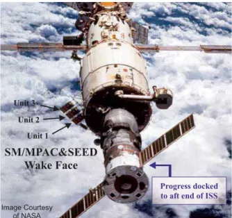
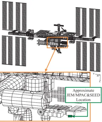
Actually, SM/MPAC&SEED was expected to encounter a different artificial space environment than JEM/MPAC&SEED because the SM is located at the rear of the ISS and JEM is scheduled to be attached at the front (see Fig. 1). Contamination
Fig. 1 Illustration of the ISS and location of both SM/MPAC&SEED and JEM/MPAC&SEED.
3.2 History of the SM/MPAC&SEED development
In September 1998, NASDA began consulting with the Russian Federal Space Agency (Roskosmos) about utilization of the Russian SM as a precursor mission to JEM & JEM/EF. An implementation plan was developed, and a contract for multipurpose experiment projects for MPAC&SEED and High Definition Television (HDTV) was signed in June 1999 [11]. In addition, NASDA began to develop SM/MPAC&SEED in early 1999. Figure 2 presents the schedule of SM/MPAC&SEED development in Russia and Japan.
2001 Russia
Japan
2002 2000
1999
CDR Specific Design PFM
IVA training Model
PSR PSR
Manufacture Manufacture
PFT
IVA Crew training Launch
21 August May EVA Crew training January
Ground support in launch site
#1 Retrieval
2001 Russia
Japan
2002 2000
1999
CDR Specific Design PFM
IVA training Model
PSR PSR
Manufacture Manufacture
PFT
IVA Crew training Launch
21 August May EVA Crew training January
Ground support in launch site
#1 Retrieval
Fig. 2 Schedule of the SM/MPAC&SEED development
Some photographs of the development phase are shown.
Figure 2 shows an External Vehicle Activity (EVA) training scene in Gagarin Cosmonauts Training Center (GCTC) in January 2001. Figure 3 depicts a SM/MPAC&SEED launch container in a sterilization room in the Baikonur Cosmodrome immediately before launch.
Fig. 3 EVA training in GCTC
Fig. 4 A SM/MPAC&SEED launch container in sterilization room immediately before launch
3.3 System description in the orbit
The overall dimensions of a flight SM/MPAC&SEED unit are W570 mm u H900 mm u D158 mm. Figure 5 depicts one unit of SM/MPAC&SEED. Ram and wake sides of the unit correspond to the ram and wake directions of the ISS. Samples are installed on holders stored in the SM/MPAC&SEED.
Sample holders can be extracted from the SM/MPAC&SEED to reduce the return weight. The sample holder was packaged by an ISS astronaut and returned to the ground by a Soyuz spacecraft.
Three identical SM/MPAC&SEED units (MPAC&SEED #1, #2, and #3) were flown and attached to the SM.
3.3.1 MPAC experiment
The MPAC is a passive experiment designed to sample micrometeoroids and space debris. Samples of three types were prepared to capture and measure micro-particles for MPAC.
Silica-aerogel (hereinafter, aerogel) is a transparent and porous solid with nanosized holes. It is used for intact capturing of dust particles and also used for estimations of impact parameters (incident direction, particle diameter, and impact velocity) based on the impact track morphology. Polyimide foam was prepared to capture large debris. An aluminum plate was used to record Velocity vector
Location of SM/MPAC&SEED
Location of JEM/MPAC&SEED (Planned)
(c)Roskosmos/RSC-Energia
Fig. 5 An SM/MPAC&SEED unit with both front (Ram side) and back (Wake side) shown.
3.3.2 SEED experiment
The SEED is a space material exposure experiment. The SEED consists of 28 samples, as outlined in Table 1. Samples were proposed by JAXA, universities, and companies in Japan and were selected by JAXA based on the frequency of use and prospective future use [12–14]. The SEED experiment also includes space environment monitoring samples, which monitor the total dose of AO, UV, space radiation, and temperature [15].
Table 1 SEED samples
3.3.4 SM/MPAC&SEED launch & operation
Three identical SM/MPAC&SEED units (SM/MPAC&SEED #1, #2, and #3) were flown and attached to the SM. The SM/MPAC&SEED was launched aboard a Progress M-45 on 21 August, 2001. The SM/MPAC&SEED was unpacked and constructed during Intra Vehicular Activity (IVA) (see Fig. 6). At 09:17 UT on 15 October 2001, all three units were mounted on the handrail outside the SM by extra-vehicular activity (EVA) (see Fig. 7). On 26 August 2002, the first unit of SM/MPAC&SEED, SM/MPAC&SEED #1, was retrieved by
was repositioned to the location that had been occupied by MPAC&SEED #2. Figure 10 depicts the SM/MPAC&SEED configuration after this second EVA. Finally, SM/MPAC&SEED
#3 was retrieved on 18 August 2005 (after 1403 days) (see Fig.
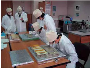
11). All SM/MPAC&SEED holders arrived on the ground in the Republic of Kazakhstan and were moved to Moscow. A primary check was performed there before transport to Japan. Figure 12 shows the third primary check out scene in October 2005.
Fig. 6 IVA for SM/MPAC& SEED construction
Fig. 7 Orbit configuration of the entire MPAC& SEED (October 2001)
Solid line: SM/SEED and monitoring samples Dashed line: SM/MPAC samples
Ram side
Wake side
100 mm
Potting Potting compound
Adhesion Adhesive
Thermal control White paint
Thermal control Flexible OSR
Thermal control Modified polyimide film
Deployable structures Japan Aerospace Exploration
Agency Loaded & unloaded polyimide film (UPILEX-S)
Lubrication IHI Aerospace
MoS2 coated Ti alloy
Cu-/ CuBN/TiN/MoS2-coated SUS304
Lubrication National Institute for Materials Science
SUS304
Mechanism application Tohoku University
Ball-bearing (3 types) TiN-coated Al / Al2O3
SiC (reaction sintering / Hot pressed)
Structural and functional materials Tokyo Institute of
Technology AlN
Deployable structures Hokkaido University
PEEK (loaded & unloaded)
Structural materials Fuji Heavy Industries Ltd.
CF/polycyanate, PIXA
Main Use Organization
Sample name
©Roskosmos/RSC-Energia
©Roskosmos/RSC-Energia
Fig. 8 EVA for deconstructing SM/MPAC&SEED #1 (August 2002)
Fig. 9 Orbit configurations of MPAC& SEED #2 & #3 (August 2002)
Fig. 11 Removal of the MPAC& SEED #3 from the ISS by an astronaut, who is visible on the right. (August 2005).
Fig. 12 Primary check-out in Moscow after retrieval (October 2005).
Three sets of the retrieved samples were analyzed. The first conference on the post retrieval analysis results was held on 8 March 2004 [16]. The second conference was held on 21 January 2006 [17]. Finally, the third conference, the international symposium for comprehensive analysis for all retrieved samples, was held in 10–11 March 2008.
4. Summary and conclusions
A unique space material exposure experiment, the SM/MPAC&SEED experiment, was conducted. For this experiment, three identical components were manufactured: the three were exposed simultaneously; each was retrieved individually after a different period of time. It was the world's first such trial. This method can compare aging deterioration of materials placed at almost the same position.
Analysis results are reported in this special publication.
Acknowledgments
The authors would like to thank Mr. Mitsuyasu Kato in JAXA, Ms. Chie Saito, of JAXA at that time, Mr. Ichiro
©Roskosmos/RSC-Energia
©Roskosmos/RSC-Energia
©Roskosmos/RSC-Energia
involved in the development and operation of the SM/MPAC&SEED experiment.
References
[1] Stein B. A. and Young P. R, LDEF Materials Data Analysis Workshop, NASA CP-10046, 1990.
[2] Levine A. S., LDEF-69 Months in Space 1st Post-Retrieval Symposium, NASA CP-3134, 1992.
[3] Levine A. S., LDEF-69 Months in Space 2nd Post-Retrieval Symposium, NASA CP-3194, 1993.
[4] Fukatsu Tsutomu et al., “Post-flight Analysis of the exposed materials on the EFFU”, Proc. of the 7th Symposium of Materials in a Space Environment, pp. 287-292, 1997 [5] Scialdone J. J. et al., “Atomic Oxygen and Space
Environment Effects on Aerospace Materials Flown with EOIM-III Experiment”, NASA TM-104636, 1996.
[6] http://matdb.jaxa.jp/SpaceExperiment/Image/MFD-ESEM- E.pdf
[7] Silverman E.M., “Space Environmental Effects on Spacecraft: LEO Materials Selection Guide”, NASA CP-4661, 1995.
[8] Michael J. Neish, et al., “Passive Measurement Of Dust Particles on the ISS Using MPAC: Experiment Summary, Particle Fluxes And Chemical Analysis”, Proc. of the Fourth European Conference on Space Debris, Darmstadt, Germany, 18–20 April 2005 (ESA SP-587, August 2005)
[9] Tachi Y. et al., “Outline of space environment exposure experiment on ISS”, Proc. of the 22nd International Symposium on Space Technology and Space, pp. 1455-1459, 2000.
[10] Koga K. et al., “Space environment data acquisition equipment – attached payload on the international space station”, COSPAR Colloquia Series Vol. 14,
"Solar-Terrestrial Magnetic Activity and Space Environment" Edited by H. Wang, R. Xu, pp. 365-366, 2002.
[11] Igor Sorokin et al., “Japanese-Russian cooperation on International Space Station now and in the future”, IAC-05-B4.3.03, 56th IAC, 2005.
[12] Ichiro Yamagata, et al., “Overview of the micro-particles capturer and space environment exposure device (MPAC&SEED) experiment”, Proc.
of the 10th International Symposium on “Materials in a Space Environment” (ISMSE) and 8th International Space Conference on “Protection of Materials and Structures from the Space Environment” (ICPMSE), June 2006.[13] Imai Fumikazu, Imagawa Kichiro, “NASDA’s Space Environment Exposure Experiment on ISS – First Retrieval of SM/MPAC&SEED –”, Proc. of
the 9th Symposium of Materials in a Space Environment, pp.589–594, June 2003.
[14] Yugo Kimoto, Ichiro Yamagata, Junichiro Ishizawa, Eiji Miyazaki, Naoko Baba, and Mitsuyasu Kato, “Japanese
using the SEED experiment”, Proc.of the 10th International Symposium on “Materials in a Space Environment”
(ISMSE) and 8th International Space Conference on
“Protection of Materials and Structures from the Space Environment” (ICPMSE), June 2006.
[16] Proc. on “International Space Station Russian Service Module (SM) / MPAC & SEED 1st Post – Retrieval conference (in Japanese), (2004).
[17] Proc. on “International Space Station Russian Service Module (SM) / MPAC & SEED 2nd Post – Retrieval conference ((in Japanese), JAXA-SP-06-021 (2007).
Chiaki Kamakura et al., “Outline of space environment exposure experiment on ISS”, Proc. of the 22nd International Symposium on Space Technology and Space, pp. 1455–1459, 2000.
Imai Fumikazu and Imagawa Kichiro, “NASDA’s Space Environment Exposure Experiment on ISS – First Retrieval of SM/MPAC&SEED –”, Proc. of the 9th Symposium of Materials in a Space Environment, pp. 589–594, June 2003.
Toshihiko Inoue, et al., “Evaluation and Analysis of the First-Retrieved Unit of the Space Environment Exposure Device (SM/MPAC&SEED)”, Proc. of the 24th International Symposium on Space Technology and Space, (CD-ROM), 2004.
Toshihiko Inoue, et al., “Evaluation and Analysis of the First-Retrieved sample of the Space Environment Exposure Device (SM/MPAC&SEED)” (in Japanese), 20th Japan Society of Microgravity Application (JASMAC-20), 2004.
Ichiro Yamagata, et al., “Overview of the micro-particles capturer and space environment exposure device (MPAC&SEED) experiment”, Proc.of the 10th International Symposium on “Materials in a Space Environment” (ISMSE) and 8th International Space Conference on “Protection of Materials and Structures from the Space Environment”
(ICPMSE), June 2006.
Kazuyuki Mori, Hiroyuki Shimamura, Takashi Nakamura, and Mineo Suzuki, “Evaluation of Space Materials by Space Environment Exposure Device ” (in Japanese), Transactions of the Japan Society for Aeronautical and Apace Sciences, Vol.54, No.633, pp.298-305, 2006.
Ichiro Yamagata, Hiroyuki Shimamura, and Eiji Miyazaki,
“Evaluation of 2nd retrieved samples for micro-particles capturer and space environment exposure device on the Russian service module (SM/MPAC&SEED) of the international space station”, (in Japanese), Proc. of the Joint Work Shop of IAT and ISAS in JAXA, 2006.
Yugo Kimoto, Ichiro Yamagata, Junichiro Ishizawa, Eiji Miyazaki, Naoko Baba, and Mitsuyasu Kato, “Japanese Space Materials Exposure Experiment Utilizing International Space Station”, IAC-06- B4.3.08, 57th IAC, 2006.
Yugo Kimoto, Mineo Suzuki, Ichiro Yamagata, Eiji Miyazaki, Junichiro Ishizawa, Naoko Baba, Kazuyuki Mori, and Hiroyuki Himamura, “Overview of SM/MPAC & SEED experiment” (in Japanese), Proc. on “International Space Station Russian Service Module (SM) / MPAC & SEED 2nd Post – Retrieval conference, JAXA-SP-06-021 2007.
of Japan, in press, 2008.
Yugo Kimoto1, Keiichi Yano2, Junichiro Ishizawa1, Eiji Miyazaki 1
1Institute of Aerospace Technology, Japan Aerospace Exploration Agency, Tsukuba, Ibaraki 305-8505, Japan
2Space Utilization and Information Technology Division Information Communications Systems Group Space Engineering Development Co., Ltd.
Tsukuba, Ibaraki 305-0032, Japan
A space materials exposure experiment was performed on the International Space Station (ISS) using the Micro-Particles Capturer and Space Environment Exposure Device (MPAC&SEED) developed by the Japan Aerospace Exploration Agency (JAXA). The experiment was executed on the exterior of the Russian Service Module (SM) of the ISS. The monitoring samples on SEED yield space-environment data such as AO, UV, fluence and space radiation dose data. The exposure and monitoring samples were retrieved after 315 days (about 10 months) and 865 days (about 28 months) and 1403 days (about 46 months) of exposure. This paper presents an analysis result of monitoring samples and orbital and attitude flight information of ISS during the SM/MPAC&SEED mission.
Keywords: MPAC&SEED, ISS Service Module, Space Environment Monitoring Samples, AO, UV, TID 1. Introduction
The SM/MPAC&SEED was a passive experiment that used neither a power source nor communication. Therefore, in-situ information was not telemetered from space. Samples for monitoring the total dose of AO, UV, space radiation, and temperature were situated on board. This paper presents experimental methods along with results of analyses of the space environment derived from space environment monitoring samples.
2. Space Environment Monitoring Samples 2.1 System description
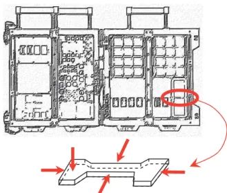
Figure 1 presents a photograph of two trays of an MPAC&SEED unit. Each unit had four trays. The temperature-monitoring sample was mounted on the back of all four trays; the remaining monitoring samples were mounted on two trays. The front face of the MPAC&SEED was designated as “ram”; the back face was termed “wake.” However, this orientation meant little because the ISS flight attitude often changed to maximize power and minimize negative thermal effects. The result of this directional analysis is described in a later section. This section explains detailed specifications for each monitoring sample.
For temperature monitoring, a thermolabel in a tray measured only the maximum temperature.
2.2 Monitoring sample
2.1Atomic Oxygen (AO) monitoring
Carbon films and Vespel (SP-1) were selected for AO monitoring. Vespel is made from aromatic polyimide powder.
Kapton-100H was selected for use as the AO monitoring sample on the ESEM mission [1]. Vespel (t=500 μm) is thicker than
Vespel for its greater thickness. Ground AO irradiation testing was conducted to calibrate the atomic oxygen fluence. We conducted irradiation tests at JAXA’s Combined Space Effects
Alanine dosimeter RADFET
TLD
Polyurethane Polyurethane Vespel
Vespel
Alanine dosimeter
PAMDEC RADFET
PAMDEC
TLD (a) Tray No.2 (Ram face)
(b) Tray No.2 (Wake face)
Fig.1 Photographs of the monitoring samples on an MPAC&SEED unit.
test specimen in orbit is derived as follows.
(1) A
cm W atoms AOFluence
x x '
U ] Re /
[ 2
In that equation,Uҏ [= 1.45 g/cm3] and A [= 3.14 cm2].
0 2 4 6 8 10 12 14 16 18 20
0.00E+00 2.00E+20 4.00E+20 6.00E+20 8.00E+20 1.00E+21 1.20E+21 AO Fluence [atom s/cm2]
Mass loss'W [mg]
Fig. 2 Vespel mass loss attributable to AO exposure. The X-axis represents AO fluence; the Y-axis shows the mass difference from the initial value, which is divided by the density and exposed surface area.
We cut a 125-μm-thick carbon film into 1 mm × 8 mm strips and integrated the film into a small device called a Passive Atomic-Oxygen Monitoring Device Equipped with Carbon Film (PAMDEC), which consists of five strips, with one strip masked using copper tape. We arranged these strips on 20 mm × 18 mm FR-4 (glass, epoxy, copper-clad laminates). Figure 3 presents a photograph of the PAMDEC. This carbon film was used as an Atomic Oxygen Monitor (AOM) sensor aboard the Japanese Experiment Module Exposed Facility (JEM-EF) on the ISS [2].
Other carbon-based atomic oxygen actinometer sensors were developed [3]. The AO eroded the carbon film while increasing its resistance. We calibrated the AO fluence, comparing it to the resistance of the PAMDEC and the ground AO-irradiation test data.
of sample was used in the ESEM [1] and EFFU missions [4]. For the Passive Optical Sample Assembly (POSA)-1 experiment mounted on the Mir space station from March 1996 to October 1997, VUV diodes were used for monitoring VUV radiation [5].
Solar-absorption (Ds) data, along with calibration data acquired from the Xe-resonance lamp-irradiation test, helped us to evaluate the UV fluence. We arranged the samples on gel sheets in a vacuum chamber to prevent increased temperatures caused by the Xe lamp, which contains an infrared wavelength region.
Figure 4 depicts the calibration curve for this sample.
0 100 200 300
0 0.05 0.1 0.15 0.2
'Ds
UV fluence [ESD]
Fig. 4 Calibration curve for UV monitoring sample. The X-axis represents the difference of solar-absorption (Ds) from the initial value ('Ds); the Y-axis shows the UV fluence.
2.3 SPACE-RADIATION EFFECT: TOTAL IONIZING DOSE (TID)
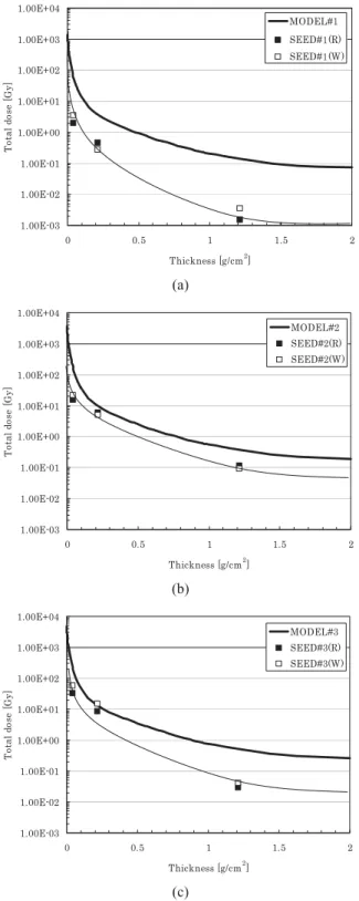
We used dosimeters of three types to evaluate the effect of space radiation: a thermo-luminescent dosimeter (TLD), an alanine dosimeter, and a radiation-sensitive field-effect transistor (RADFET). The TLD was also used on the ESEM mission [1]. A TLD is a small device that is used to evaluate radiation exposure by measuring the amount of visible light emitted by a crystal when heated in the detector. The amount of emitted light depends on the ionizing irradiation exposure. We arranged six TLDs behind a 4.5-mm-thick aluminum shield on both the ram and wake sides of a sample tray.
An alanine dosimeter is a solid device consisting mainly of alanine and polystyrene. The radical density increases in proportion to the dose of radiation received. The relative density of the radical is measured using Electron Spin Resonance (ESR).
Four alanine dosimeters were arranged behind a 0.15-mm aluminum shield with white paint on both the ram and wake sides of a sample tray.
A RADFET is a specially designed P-channel metal oxide semiconductor (PMOS) transistor with a thick gate oxide, which is optimized for increased radiation sensitivity. The RADFET is suitable for real-time space dosimetry missions in terms of its cost, weight, and low power consumption specifications [6, 7].
The RADFETs used in MPAC&SEED were 400-nm implanted gate-oxide devices manufactured by the Tyndall National Institute of Ireland. We arranged three RADFETs on both the ram and wake sides of a tray. This RADFET had a 0.8-mm-thick equivalent aluminum lid.
20mm
18mm
Carbon (1 mm x 8 mm x 0.12 5mm)
#1 #2 #3 #1 #2 #3 Maximum Temperature
[°C]
50a 60b
50a 90b
60a 90b
㧙 㧙 㧙
AO [atoms/cm2]
Vespel 2.04 × 10²⁰ 2.57 × 10²⁰ 2.70 × 10²⁰ 1.61 × 10²⁰ 2.05 × 10²⁰ 3.09 × 10²⁰ PAMDEC 2.41 × 10²¹ 1.36 × 10²¹ 1.37 × 10²¹ 1.93 × 10²¹ 1.22 × 10²¹ 4.82 × 10²¹
UV [ESD] 18.1 15.8 13.4 122.2 201.0 205.5
TID [Gy] Alanine
dosimeter c 1.95 15.3 32.0 3.5 21.9 58.3
RADFETd 0.44 5.99 8.59 0.27 4.92 14.9
TLDe 1.46 × 10⁻³ 0.12 0.29 3.41 × 10⁻³ 0.09 0.04
a At approximately 5 mm depth in Tray No. 1 and 2.
b At approximately 1 mm depth in Tray No. 3 and 4.
Shield thickness; c 0.04 [g/cm2], d0.2 [g/cm2],e 1.2 [g/cm2] 3. Derivation results from the monitoring samples
Table 1 presents results derived from sample monitoring.
The first-retrieved monitoring sample data are labeled as #1; the second-retrieved are labeled as #2; the third-retrieved are labeled as #3.
The maximum temperatures in the three trays were 50–90°C. The AO fluence was 1020 atoms/cm2 from Vespel and 1021 atoms/cm2 from PAMDECs. The MPAC&SEED #1 data showed higher values than those of MPAC&SEED #2, although MPAC&SEED #2 had longer exposure than #1 in the AO fluence. A similarly unexpected result also occurred in the UV monitoring samples. The measured intensity of UV in the wake face was greater than that from the ram face. The TID data were dependent on the shield thickness.
4. Discussion
Orbital and attitude flight information of the ISS during this experiment period, provided by RSC Energia, was analyzed.
The average flight altitude was 371 km. the inclination was 51.64 deg. Figure 5 shows ISS post-flight orbital and attitude changes. Table 2 shows the average orbital and attitude. The ISS has different attitude modes until the main solar arrays are in position. The main attitudes are the X-axis in the Velocity Vector (XVV), the X-Axis Perpendicular to the Orbit Plane (XPOP), and the Y-axis in the Velocity Vector (YVV). The ram and wake faces are oriented along the ram and wake directions of the ISS when the ISS flies in XVV mode. However, during XPOP mode and during YVV mode, the MPAC&SEED faces a direction that is perpendicular to the flight direction. During the first year of MPAC&SEED #1, the ISS spent 59% of its time in XVV mode and 41% in XPOP mode. During MPAC&SEED #2, the ISS spent 54% of its time in XVV mode and 46% in XPOP and YVV mode. Therefore, both the ram and wake faces were pointed in the flight direction.
We compared flight data and data from the space-environment model for the atomic-oxygen fluence and calculated the AO fluence using the MSIS-86 model in the Space Environment & Effects System (SEES) [8] during 15 October 2001 – 26 February 2004. We used the F10.7 and Ap index data available from NOAA Space Weather Data and
6700 6710 6720 6730 6740 6750 6760 6770 6780 6790 6800
2001/10/15 2002/4/15 2002/10/15 2003/4/15 2003/10/15 2004/4/15 2004/10/15 2005/4/15 Date
Semi-major axis䋨km䋩
Fig. 5 ISS post-flight orbital and attitude change.
Table 2 Average orbital information Orbital radius [km] 6748.904 (370.77a) Eccentricity [° ] 0.00071
Inclination [° ] 51.64
a Re=6378.134 km
1.00E+19 1.00E+20 1.00E+21 1.00E+22
0 200 400 600 800 1000 1200 1400 1600
Total days [day]
AO Fluence [atoms/cm2 ]
MODEL PAMDEC (R) PAMDEC (W) Vespel (R) Vespel (W)
Fig. 6 AO fluence data compared to PAMDEC and Vespel monitoring sample data and model calculations.
and wake faces were less than the values of the SEES-model calculation, which suggests that a contamination effect is responsible for the monitoring environment.
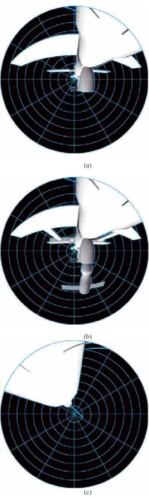
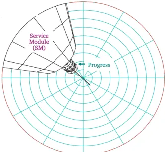
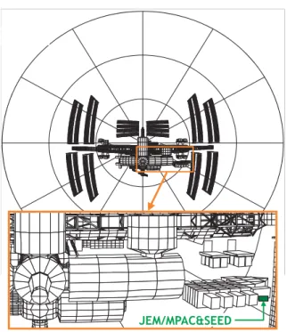
We also compared flight data and data from the space-environment model for the UV fluence and calculated the UV fluence using SEES [8]. In this analysis, a cube was used in place of the real ISS shape. We also considered the flight-direction change in our calculation. In Fig. 7, the UV fluence from the polyurethane sheet on the wake side was 1.3 times the data from the space-environmental model. However, the value from the ram side reached almost one-tenth of the data from the space-environment model. Moreover, the second-retrieved data were less than the first-retrieved data, which suggests that the ram side was not exposed to UV because the ISS itself or some components in the field view of the MPAC&SEED trays shaded the UV irradiation. Figure 8 shows fish-eye images from ram and wake sides of the MPAC/SEED.
Actually, the Russian segment elements had the largest view factors to the MPAC&SEED trays in the ram side. The Russian segment elements of concern include the Functional Cargo Block (FCB), Service Module (SM), and Docking Compartment 1 (DC1). In addition, visiting vehicles (Orbiter, Soyuz, and Progress) had considerable view factors when mated to the ISS [10]. The field of view from the wake side is clear during the MPAC&SEED mission period. Furthermore, XPOP is the attitude at which the X-axis is perpendicular to the orbital plane;
therefore, the +X direction is facing anti-sun. These reasons suggest that the ram side was not exposed to UV.
0.0 50.0 100.0 150.0 200.0 250.0 300.0 350.0 400.0
0 200 400 600 800 1000 1200 1400 1600
Total days [day]
UV [ESD]
Polyurethane(W) MODEL Polyurethane(R)
Fig. 7 UV fluence compared to data from polyurethane UV monitoring samples and model calculations.
(a)
(b)
(c)
Fig. 8 Field view analysis from the MPAC&SEED (a: From ram side in 15 October 2001 (exposure just started), b: From