Ni subwavelength grating/SiO
2/Ag based optical magnetic field sensor
with normal incident geometry
Yuusuke Takashima*
a, Kouhei Moriiwa
b, Masanobu Haraguchi
a, c, Yoshiki Naoi
a, ca
Graduate School of Technology and Science, Tokushima University
bGraduate School of Advanced Technology and Science, Tokushima University
c
Institute of Post-LED Photonics, Tokushima University
2-1 Minami-josanjima, Tokushima, Japan 770-8506
ABSTRACT
A sensitive optical magnetic field sensor was experimentally demonstrated using Ni-subwavelength grating (SWG) combined with a SiO2/Ag plasmonic structure. We fabricated the Ni-SWG structure on the Ag/SiO2 structure using electron beam lithography and a liftoff process. As a result, a dip in the reflection spectra with normal incidence was obtained at a wavelength of 530 nm. The reflectivity at the dip position significantly decreased with the intensity of the magnetic field applied to the structure. When a magnetic field of 43 mT was applied, the change in reflection reached approximately 4% of that without magnetic field. The experimental results indicate that our sensor achieves millitesla order of sensitivity for the magnetic field. The electromagnetic field distribution around the Ni-SWG/SiO2/Ag calculated using the finite-difference time-domain method clarified the reason for the high sensitivity of our sensor.
Keywords: Magnetic field sensor, ferromagnetic subwavelength grating, surface plasmon polariton
1. INTRODUCTION
With the development of the Internet of Things (IoT) society, highly sensitive magnetic field sensors are becoming more important in many fields, such as biology, medical sciences, and engineering1, 2. Various types of magnetic field sensors have been realized, such as Hall elements3, giant magnetoresistive sensors4, and superconducting quantum interference devices5. In particular, optical sensor for quantifying the magnetic field has attracted much attention due to its rapid response speed, low influence from electromagnetic noises, and less electric wiring. These advantages are attractive to sensing devices for practical use, for example a compact position sensor with high radiation endurance. Several groups have developed highly sensitive optical sensors for measuring the magnetic field using Bragg fiber6, photonic crystal fiber7, microstructured fiber8, Fabry–Perot and Mach–Zehnder interferometers9, 10. Although these sensors are highly sensitive, advanced fabrication techniques and special experimental setups, such as micrometer order tapered fiber, high performance spectrometer, wavelength variable laser, and oblique incident system, are required, which significantly restrict the practical use of magnetic field sensors.
In this study, a highly sensitive optical magnetic field sensor with simple setups was experimentally demonstrated using ferromagnetic subwavelength grating (SWG) combined with a dielectric/metal plasmonic structure. The ferromagnetic SWG was fabricated on a dielectric/metal layer using electron beam (EB) lithography techniques, and the dip of the reflection spectra, from the fabricated structure, was observed. The reflectivity at the dip position significantly decreased when an external magnetic field perpendicular to sample surface was applied and magnetic fields of millitesla order were detected. Moreover, we discussed and clarified the reason of such high sensitivity of our sensor by employing the finite-difference time-domain (FDTD) calculation of the electromagnetic field distribution.
*takashima@ee.tokushima-u. ac.jp; phone +81-88-656-7447; fax +81-88-656-7447
Nanoengineering: Fabrication, Properties, Optics, Thin Films, and Devices XVI, edited by Balaji Panchapakesan, André-Jean Attias, Proc. of SPIE Vol. 11089, 110891V · © 2019 SPIE · CCC code: 0277-786X/19/$21 · doi: 10.1117/12.2529017
Proc. of SPIE Vol. 11089 110891V-1
Downloaded From: https://www.spiedigitallibrary.org/conference-proceedings-of-spie on 06 Sep 2019 Terms of Use: https://www.spiedigitallibrary.org/terms-of-use
2. DESIGN RULE OF THE SWG/DIELECTRIC/METAL STRUCTURE AND ITS FABRICATION
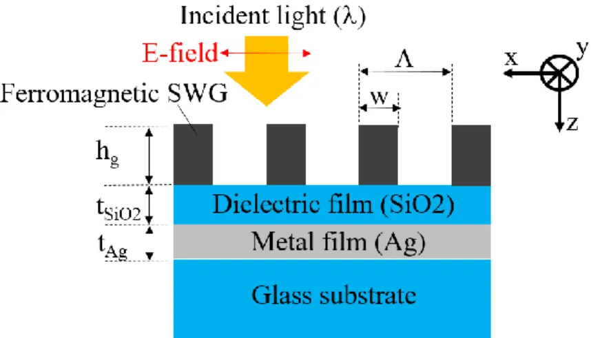
In this section, we mention the design rule of our magnetic field sensor. The sketch of our magnetic field sensor with ferromagnetic SWG/dielectric/metal structure is shown in Fig. 1, where , , hg, w, tSiO2, and tAg correspond to the incident wavelength, the grating period, the height of the grating, the width of grating finger, the thickness of SiO2 and Ag films, respectively. SiO2 and Ag films are selected as the dielectric/metal plasmonic structures and are deposited on the glass substrate. Meanwhile, the ferromagnetic SWG is placed on top of the SiO2 film.We considered the normal incidence of the p-polarized plane wave whose electric field is perpendicular to SWG fingers (Red arrow shown in Fig. 1). The incident light is diffracted by the SWG, and the various order diffractions are generated. In the case of SWG, the diffraction orders, except the 0th, become an evanescent wave, which have a larger lateral wavenumber (x-direction) than that of the incident light, due to the large wavenumber modulation caused by the shorter grating period than that of the incident wavelength11. On the other hand, surface plasmon (SP) modes might exist at the SiO2/Ag films’ interface. If the distance between the SWG and the interface is smaller than the attenuation length of the SP mode, higher order diffractions can excite the surface plasmon polariton (SPP) modes at the interface, provided that the diffractions’ wavenumbers coincide with that of the SPP modes12. As a result, a reflectivity dip is observed, as part of the incident light’s energy is utilized for excitation of SPP, which is also reradiated to the incident region by the SWG. The excitation and the reradiation of SPP contribute to the reflectivity of our structure.
When the external magnetic field was applied to our structure, the ferromagnetic SWG was magnetized. The magnetization influenced the movement of light’s induced electron dipoles in the SWG, and non-diagonal components of the dielectric constant of the ferromagnetic SWG appeared13, 14. As the reradiation condition of SPP was considerably modified by non-diagonal dielectric components, the reflectivity dip, resulting from the excitation of SPP, sensitively changes by applying a magnetic field. As a result, the applied magnetic field could be measured by our structure combined with a normal incident system.
Figure 1. Sketch of the SWG/dielectric/metal based optical magnetic field sensor. The red arrow indicates the electric field of the incident light. The incident light is normal to the ferromagnetic SWG/dielectric/metal structure.
Using the dispersion relation of the SPP at the SiO2/Ag interface, we set our structural parameters in order to coincide the wavenumbers of the SPP and the diffraction (1st order in this paper) at the wavelength of 550 nm, which was selected in order to facilitate the experiment and its treatment. The refractive induces of Ag and SiO2 were taken from these references15, 16 and the structural parameters were = 300 nm, w = 150 nm, h
g = 100 nm, respectively. The 40 nm and 60 nm thickness of Ag and SiO2 films were also chosen in order to overlap the fields of the higher order diffraction and that of SP. We employed Ni as the ferromagnetic SWG material, due to its large saturated magnetization of the nanosized Ni rods17.
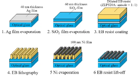
Figure 2 describes the fabrication process of Ni-SWG/SiO2/Ag structure. At first, the 40 nm thick Ag film was evaporated on the optical glass substrate with a heating resistant method. The 60 nm thick SiO2 film was, afterward, evaporated and
Proc. of SPIE Vol. 11089 110891V-2
Downloaded From: https://www.spiedigitallibrary.org/conference-proceedings-of-spie on 06 Sep 2019 Terms of Use: https://www.spiedigitallibrary.org/terms-of-use
placed on the Ag film using electron beam evaporation. We spin-coated EB resist film (ZEP520A: Zeon) at 3000 rpm and for 90 s. The EB resist was diluted by anisole (resist: anisole = 1: 1). After coating, the sample was baked at 120 °C for 30 minutes. We performed the SWG pattern onto the resist film using EB lithography with a 50 kV acceleration voltage (ELS 7500: Elionix). The patterned region was 300 m x 300 m and the Ni film of 100 nm of thickness was evaporated on the patterned resist, which was removed afterwards. Figure 3 shows the surface image of the fabricated sample by scanning electron microscope (SEM). The fabricated grating period and width of the grating finger are 300 nm and 150 nm, respectively.
Figure 2. Flow of the fabrication process of the Ni-SWG/SiO2/Ag based magnetic field sensor
Figure 3. SEM top view of the fabricated sample after the EB resist lift-off process
Proc. of SPIE Vol. 11089 110891V-3
Downloaded From: https://www.spiedigitallibrary.org/conference-proceedings-of-spie on 06 Sep 2019 Terms of Use: https://www.spiedigitallibrary.org/terms-of-use
3. EXPERIMENTAL RESULTS AND DISCUSSION
We measured the optical characteristics and the magnetic response of the fabricated sample in order to evaluate our sensor’s performance. In this section we are going to explain the experimental measurement system. A halogen lamp was selected as the broad spectral light source. The lamp’s light, which was collimated by planer-convex lens, passed through the polarizer, making it p-polarized. The p-polarized light was, afterward, focused on the fabricated Ni-SWG region by focusing lens (magnification: x 20, NA: 0.46). The light normally reflected from the sample was detected using a spectrometer (Blue wave: StellarNet). The sample was placed on top of a solenoid coil electromagnet in order to be influenced by its magnetic field, whose direction is perpendicular to the sample surface. The applied magnetic field intensity was measured by a gauss meter (Lake Shore 410). The black-coated Al film was inserted between the sample and the electromagnet to prevent the light’s reflection from the electromagnet.
Figure 4(a). Normal reflectivity of the fabricated Ni-SWG on SiO2/Ag film as a function of the incident wavelength. (b) Dependence of the reflectivity at the dip on the value of the applied magnetic field perpendicular to the sample surface.
The normal reflection spectra of the fabricated Ni-SWG/SiO2/Ag structure is shown in Fig. 4 (a). We observed a reflectivity dip behavior around the wavelength of 530 nm in Fig. 4 (a), as indicated by our prediction in section 2. The dependence of the reflection spectra with the applied magnetic field value is shown in Fig. 4 (b). The minimum reflectivity decreases with the magnetic field value until 43 mT. At this point, no reflectivity change is observed if the magnetic field value is increased. This saturation can be attributed to the magnetization properties of the Ni. When we applied magnetic field of 43 mT, the variation of the reflectivity was approximately 4% of that without magnetic field. These experimental results indicate that our optical magnetic field sensor realize a millitesla order sensitivity, almost the same order as the measures of other optical magnetic sensors6-9, 18 (assuming that the wavelength resolution of spectrometer is 1 nm), without complex and expensive experimental setup.
In order to investigate and discuss the reason of our sensor sensitivity, the calculation for the electromagnetic field distribution around the reflectivity dip wavelength was also performed by the FDTD method. The model is the same as that in Fig. 1. The grating length for the y-direction is considered infinite and the periodic boundary condition was applied for x-direction. The electromagnetic field distribution of our sensor was calculated for normal incidence of the p-polarized plane wave propagating along z-direction. The calculation conditions’ details are shown in our previous reports18. The x- and z-component of the electric field distribution are shown in Fig. 5 (a) and (b), respectively. The field amplitudes were normalized by that of the incident field. The incident field is distorted and diffracted from the Ni-SWG as shown in
Proc. of SPIE Vol. 11089 110891V-4
Downloaded From: https://www.spiedigitallibrary.org/conference-proceedings-of-spie on 06 Sep 2019 Terms of Use: https://www.spiedigitallibrary.org/terms-of-use
Fig. 5 (a), and the z-direction components are generated around Ni-SWG and Ag/SiO2 interface as shown in Fig. 5 (b). These distributions indicate that the diffracted light by the Ni-SWG is combined with the SP mode, propagating along the x-direction, at the interface between Ag and SiO2, as the component of the electric field does not exist for the z-component of the propagating light. Moreover, we obtained approximately 3-times higher amplitude of the z-z-component field than that of the incident field. Furthermore, the field is concentrated around Ni-SWG and Ag surface. The excited SPP, which contributes to the reflectivity of our sensor, is reradiated by Ni-SWG. When the magnetic field is applied to our sensor, the non-diagonal dielectric components of Ni-SWG are generated by the Lorenz force due to the magnetized Ni. If the high electric field is concentrated around the Ni-SWG and Ag/SiO2 surface, the Lorenz force is enhanced by the high electric field. Larger non-dielectric components of Ni are, therefore, induced and the reradiation condition of the SPP significantly modified, making the reflectivity of our sensor considerably change with the applied magnetic field. These results indicate that the compactness and simple setup of our sensor contributes for the integrated devices in the IoT society, and the theoretical calculations may lead to new design concepts of magneto-optical devices
Figure 5 (a). The x-component of electric field distribution around the Ni-SWG/SiO2/Ag structure. (b) The z-component of the electric field distribution. The field amplitudes are normalized by that of the incident field. The incident light propagates along the z-direction.
4. SUMMARY
We experimentally demonstrated optical magnetic field using Ni-SWG combined with SiO2/Ag structure. The designed Ni-SWG was fabricated on SiO2/Ag films using EB lithography and lift off techniques. The minimum reflectivity value from the fabricated sample was observed at wavelength of 530 nm, and significantly decreased with the applied magnetic field. The change of the reflectivity was 4% of that without applied magnetic field, and our magnetic field sensor realized millitesla order sensitivity with simple experimental setup. The calculated electromagnetic field distribution by FDTD method also revealed that the high electric field concentrates around Ni-SWG and Ag film surface, contributing to the high sensitivity of our sensor. These results may lead to new design concepts of magneto-optical devices.
ACKNOWLEDGMENTS
This work is partially supported by JSPS KAKENHI Grant Number JP18K04238 and LED general platform project of Tokushima University.
Proc. of SPIE Vol. 11089 110891V-5
Downloaded From: https://www.spiedigitallibrary.org/conference-proceedings-of-spie on 06 Sep 2019 Terms of Use: https://www.spiedigitallibrary.org/terms-of-use
REFERENCES
[1] Morón C., Cabrera C., Morón A., García A. and González M., "Magnetic sensors based on amorphous ferromagnetic materials: a review," Sensors 15(11), 28340-28366 (2015).
[2] Reig C., Cubells-Beltrán M.-D. and Muñoz D. R., "Magnetic field sensors based on giant magnetoresistance (GMR) technology: applications in electrical current sensing," Sensors 9(10), 7919-7942 (2009).
[3] Sharon Y., Khachatryan B. and Cheskis D., "Toward a low current Hall effect sensor," Sens. Actuators A 279, 278-283 (2018).
[4] Guedes A., Macedo R., Jaramillo G., Cardoso S., Freitas P. P. and Horsley D. A., "Hybrid GMR sensor detecting 950 pT/sqrt(Hz) at 1Hz and room temperature," Sensors 18(3), 790 (2018).
[5] Kirtley J. R., Paulius L., Rosenberg A. J., Palmstrom J. C., Schiessl D., Jermain C. L., Gibbons J., Holland C. M., Fung Y.-K.-K., Huber M. E., Ketchen M. B., Ralph D. C., Gibson Jr. G. W. and Moler K. A., "The response of small SQUID pickup loops to magnetic fields," Supercond. Sci. Technol. 29(12), 124001 (2016).
[6] Yang D., Du L., Xu Z., Jiang Y., Xu J., Wang M., Bai Y. and Wang H., "Magnetic field sensing based on tilted fiber Bragg grating coated with nanoparticle magnetic fluid," Appl. Phys. Lett. 104(6), 061903 (2014).
[7] Mahmood A., Kavungal V., Ahmed S. S., Farrell G., and Semenova Y., "Magnetic-field sensor based on whispering-gallery modes in a photonic crystal fiber infiltrated with magnetic fluid," Opt. Lett. 40(21), 4983-4986 (2015).
[8] Deng M., Huang C., Liu D., Jin W. and Zhu T., "All fiber magnetic field sensor with ferrofluid-filled tapered microstructured optical fiber interferometer," Opt. Express 23(16), 20668-20674 (2015).
[9] Costa G. K. B., Gouvêa P. M. P., Soares L. M. B., Pereira J. M. B., Favero F., Braga A. M. B., Palffy-Muhoray P., Bruno A. C. and Carvalho I. C. S, "In-fiber Fabry-Perot interferometer for strain and magnetic field sensing," Opt. Express 24(13), 14690-14696 (2016).
[10] Chen H., Shao Z., Zhang X., Hao Y. and Rong Q., "Highly sensitive magnetic field sensor using tapered Mach-Zehnder interferometer," Opt. Lasers Eng. 107, 78-82 (2018).
[11] Kikuta H., Toyota H. and Yu W., "Optical elements with subwavelength structured surfaces," Opt. Rev. 10(2), 63-73 (2003).
[12] Homola J., Koudela I. and Yee S. S., "Surface plasmon resonance sensors based on diffraction gratings and prism couplers: sensitivity comparison," Sens. Actuator B 54, 16-24 (1999).
[13] Belotelov V. I., Akimov I. A., Pohl M., Kotov V. A., Kasture S., Vengurlekar A. S., Gopal A. V., Yakovlev D. R., Zvezdin A. K. and Bayer M., "Enhanced magneto-optical effects in magnetoplasmonic crystals," Nat. Nanotechnol. 6, 370-376 (2011).
[14] Armelles G., Cebollada A., García-Martín A. and González M. U., "Magnetoplasmonics: combining magnetic and plasmonic functionalities," Adv. Optical Mater. 1(1), 10-35 (2013).
[15] Johnson P. B. and Christy R. W., "Optical constants of the noble metals," Phys. Rev. B 6(12), 4370-4379 (1972). [16] Malitson I. H., "Interspecimen comparison of the refractive index of fused silica," J. Opt. Soc. Am 55(10),
1205-1209 (1965).
[17] Ferré R., Ounadjela K., George J. M., Piraux L. and Dubois S., "Magnetization processes in nickel and cobalt electrodeposited nanowires," Phys. Rev. B 56(21), 14066-14075 (1997).
[18] Takashima Y., Haraguchi M. and Naoi Y., "Highly sensitive magnetic field sensor with normal-incidence geometry using Ni-based bilayer subwavelength periodic structure operating in visible-wavelength region," Jpn. J. Appl. Phys. 57(8S2), 08PE01 (2018).
Proc. of SPIE Vol. 11089 110891V-6
Downloaded From: https://www.spiedigitallibrary.org/conference-proceedings-of-spie on 06 Sep 2019 Terms of Use: https://www.spiedigitallibrary.org/terms-of-use