Study on electrochemical activation and application
of novel Mg alloy electrode by tension stress
application
Gang Shi
Chapter 1 Introduction ... 1
1.1 Current status of battery materials ... 1
1.1.1 Composition of the battery ... 1
1.1.2 The study of the material of the battery ... 2
1.2 Introduction of Primary batteries and secondary batteries ... 3
1.2.1 Classification of the electrochemical cell ... 3
1.2.2 Introduction of the Primary battery ... 4
1.2.3 Introduction of the Secondly battery... 7
1.3 Expectation to a magnesium alloy battery ... 9
1.3.1 Comparison of characteristics of Mg and Li ... 9
1.3.2 Magnesium alloy air cell (primary) ... 10
1.3.3 The introduction of the second battery of Mg battery ... 12
1.3.4 Effection of Vanadium Oxide inserted in Anode... 14
1.3.5 Introduction of Magnesium stem cell ... 15
1.4 Electrochemical reaction principle ... 16
1.5 Corrosion reaction of the Battery ... 18
1.5.1 Electrochemistry corrosion ... 18
1.5.2 Application of the stress corrosion ... 21
1.6 Design of magnesium electrode material ... 23
1.6.1 Selection of the added element of a new magnesium alloy ... 23
1.7 Purpose of this study ... 27
1.8 Composition of this paper ... 27
1.9 Conclusion ... 28
Reference ... 29
Chapter 2 Development of magnesium alloy electrode materials and performance evaluation ... 36
2.1 Production of the Mg-Zn-In-Se-MnS alloy ... 36
2.2 Production method of magnesium alloy plate ... 37
2.2.1 Twin-roll continuous casting ... 37
2.2.2 Manufacture of the Mg-Zn-In-Sn-MnS alloy sheet... 38
2.3 Analysis of the magnesium alloy ingredient ... 39
2.3.1 Fluorescence X-rays analysis of the magnesium alloy ingredient ... 39
2.4 Performance evaluation of Mg-Zn-In-Sn-MnS alloy ... 40
2.4.1 Observation of fine structure... 40
2.5 Experiment of tensile stress ... 41
2.6 Conclusion ... 41
Reference ... 41
Chapter 3 Evaluation of electrode performance with stress corrosion and clarification of electrochemical · stress corrosion mechanism ... 43
3.1 Advantages and mechanisms of manganese sulfide ... 43
3.2 Electrolyte selection and stress corrosion experiment ... 45
3.2.1 CV curve of KCl from 0 Mpa to 10 MPa at a distance of 10 mm ... 45
3.2.2 CV curve of KCl from 0 MPa to 10MPa at a distance of 2 mm ... 47
3.2.3 CV curve of AcONa from 0 MPa to 10 MPa at a distance of 10 mm ... 48
3.3 The theory of electro-chemical chemistry and the application of the theory of the value of the study ... 52
3.3.1 Introduction ... 52
3.3.2 Experimental material ... 52
3.3.3 Measurement of Mg concentration ... 53
3.3.4 Proposal of hybrid model ... 54
3.3.5 Mg2+ concentration changes ... 54
3.3.7 LC calculation ... 56
3.4 Conclusion ... 58
Reference ... 59
Chapter 4 Application of stress corrosion - Development of primary battery ... 60
4.1 Introduction ... 60
4.2.1 The electrochemical reaction process of corrosion simulation diagram ... 61
4.2.2 Measurements of single electrode characteristics ... 61
4.2.3 Morphologies of the magnesium alloy electrodes after tensile stress tests .. 62
4.3 Result and discussion ... 63
4.3.1.Measurements of single electrode characteristics ... 63
4.3.2.Estimation of power densities for the magnesium alloy batteries ... 65
4.3.3.Morphologies of the stressed magnesium electrodes ... 66
4.3.4 Magnesium air battery ... 69
4.4 Conclusion ... 70
Chapter 5 Mechanical control of magnesium alloy electrodes under the tensile stress for applications in non-aqueous battery electrolyte solution ... 72
5.1 Introduction ... 72
5.2 Experimental ... 74
5.3 Results and Discussion ... 78
5.4 Conclusion ... 86
References ... 87
Chapter 6 Phosphorous Recovery by the Magnesium Alloy Electrode under Tensile Stress . 88 6.1 Introduction ... 88
6.2 Experimental ... 89
6.3 Results and discussion ... 92
6.4 Conclusion ... 95
References ... 96
Chapter 7 Conclusion ... 97
Acknowledgments ... 100
Chapter 1 Introduction
1.1 Current status of battery materials
1.1.1 Composition of the battery
The battery, which is the chemical energy using electrochemical oxidation-reduction reaction (redox reaction) with the battery active material a device that converts directly to the battery energy[1-3]. In the non electrochemical redox reaction, such as corrosion and combustion, electron transfer occurs directly substance conversion without passing through an electric circuit, exothermic only. While the battery is often used as a term representing a battery, its basic cell scientific unit is cell (cell, unit cells). Cell is composed of one or more unit cells, the unit cells according to the output and capacity required are connected in series or parallel. The battery is made up of three key components to shown schematically pictorial in Fig1.1[4-7].
Fig. 1.1 The structure of battery
a. anode: With a reducing electrode or the fuel electrode, placed accept electrons from the external circuit by an electrochemical reaction itself is reduced.
b. cathode: Oxidation electrode, I receive an electron, and, with an oxidation electrode, itself is resolved by an electrochemical reaction by an outside circuit
c. electrolytes: In an ion conductor, it becomes a cathode and the migration of ions medium between anodes. Electrolytes usually dissolved acid, alkali or salt in water and other solvents with a liquid and kept ion conductivity. There is the battery using the solid electrolyte, too, and in this case a solid electrolyte operates in the temperature indicating ion tradition characteristics.
1.1.2 The study of the material of the battery
electrically isolated, between them are satisfied electrolyte. In fact of the battery mechanically isolates the negative electrode and a positive electrode with a separator, the separator is maintained ionic conductivity for the electrolyte to penetrate. Sometimes, there is a case where the electrolyte is immobilized so as difficult to flow out. Further to reduce the internal resistance of the battery, a method with a conductive grid electrode, or adding a conductive agent into has been used[18-22].
1.2 Introduction of Primary batteries and secondary
batteries
1.2.1 Classification of the electrochemical cell
energy storage medium, is connected to an energy source such as a motor and charged, and discharges as necessary. It is also used for starting power supplies for automobiles and airplanes, emergency batteries, and solid energy storage systems for load leveling. In particular, batteries which are called mechanically rechargeable batteries, in many cases, after discharging, replace the metal of the negative electrode with a new one and recharge it. A metal / air battery is a typical example. Battery as an energy conversion device is classified and it becomes like Fig. 1.2[30,31].
Fig. 1.2 Batteries are categorized from the perspective of energy conversion.
1.2.2 Introduction of the Primary battery
Primary batteries are simple power sources independent of public electric power for portable electronic or electrical equipment, lighting, cameras, computers, communication equipment, watches, calculators, memory backup and other various equipment.[32] The maximum advantage of the primary battery is its convenience, it
Chemical battery One-shot battery Secondary battery Fuel battery Physical battery Solar battery
Thermoelectric conversion battery
Atomic force battery
Biological battery Enzyme battery Microbial world
is easy to use from the viewpoint of structure, but it is not necessary for maintenance. The size and shape can be changed according to the purpose. Other advantages include shelf life, moderate energy density and power density, reliability and affordable will be cost[33,34]. Primary batteries existed 100 years ago, but until 1940 only manganese dry batteries had been used . Battery research developed greatly during World War II and after the war, not only the manganese stem battery system but also an excellent new battery was developed. The capacity has been improved from 50 Wh / Kg or less of the initial manganese stem battery system to 500 Wh / Kg of the current lithium battery. During the Second World War, even if shelf life was preserved under proper temperature, it was one year, but with convenient batteries currently in use has a lifetime of 2 to 5 years, the latest lithium battery Have storage life of more than 10 years even if they are stored at 70 ° C. Operability at low temperature has also been improved from 0 ° C. to -40 ° C and -55 ° C., and the power density has also been improved several times. In the case of a low current battery using a solid electrolyte, the shelf life is more than 20 years[35,36].
With the improvement of such characteristics, many new machines for use of primary batteries have been developed. As a result of the improvement of energy density, the size and weight of the battery were greatly reduced. This reduction contributed to the advancement of electronic technology, and many new desk radio, communication equipment, practical output equipment were made. Improvement of the power density of the primary battery brought about the size and weight of the battery. This reduction contributed to the advancement of electronic technology, and many new desk radio, communication equipment and practical electronic equipment were made. Improvement of the output density of primary batteries not only makes it possible to desktop computers, mobile phones, transceivers, and devices that have required high power of secondary batteries and external power sources, but also has troublesome charging and maintenance Resolved[37]. At present, with respect to primary batteries, the shelf life is further prolonged, while lifespan and reliability are improved at the time of battery operation, on the other hand, it is also used for devices for a long time, such as medical packaging and memory .
majority of the primary battery is a general cylindrical or flat plate battery with a capacity of 20 Ah or less. There are few large batteries to reach thousands of Ah, but it is used in special cases such as signaling equipment and military functions that require independent lower power from external power supply.
are widely used for hearing aids and other electronics equipments[46-48]. These batteries have a very high energy density even without mounting a positive electrode active material. However, there are limits to the expansion of the applications of this battery and the development of large batteries due to their operating characteristics (sensitive to temperature and humidity, short storage life, low power density). Nonetheless, due to the high energy density of this battery, metal / air batteries are considered to be used in a number of applications (desk electrical equipment, electric cars, storage batteries, mechanically charged type).
1.2.3 Introduction of the Secondly battery
Secondary batteries, that is, chargeable / dischargeable batteries, are widely used in many applications. The most familiar uses are used for car startup, lighting, ignition and so on. Others are for industrial use such as forklist, backup for emergency or power failure, etc. Demand for small secondary batteries, which is a power source for tools such as tools, toys, lights, cameras, radios or personal computers, video, mobile phones and other portable devices, is remarkable. Recently, secondary batteries are attracting attention in electric vehicles or applications for leveling power. Also, as appropriate for these applications, plans are underway to improve current battery characteristics and develop new batteries. Applications of secondary batteries can be roughly divided into the following two points.
1. Application for power storage. Used to meet the purpose of supplying the energy as required when the secondary battery is supplied with power from the primary energy source and the primary energy source becomes unusable. Examples include automobiles, airplanes, backups during emergency power outages, storage batteries for power leveling.
A feature of the secondary battery of a normal aqueous solution is that it can be charged with a high current density, the discharge curve is flat and shows excellent characteristics even at low temperatures. However, the energy density of the secondary battery is lower than that of the primary battery, and self- discharge is large. On the contrary, since the non-aqueous electrolytic solution having a lower electric conductivity than that of the aqueous solution is used as the output density, so excellent characteristics can not be expected[49].
we will predict what sort of time, or what size of the market will be used and what kind of batteries are currently used .
1.3 Expectation to a magnesium alloy battery
1.3.1 Comparison of characteristics of Mg and Li
In the periodic table, magnesium and Lithium has a diagonal location, so both have a lot of similar chemistry. Magnesium-ion technology is promising for several reasons. First, due to the natural abundance of magnesium in the earth’s crust, approximate 10000 times that of lithium, its incorporation into electrode materials is inexpensive(Table 1). Secondly, magnesium is more atmosphere stable and has a higher melting point than lithium, making it safer relative to lithium[52]. The divalent nature of magnesium ions also presents a potential advantage in terms of volumetric capacity(3833mAh/cm3 for Mg vs. 2046mAh/cm3 for Li).
Despite these positive attributes, the development of magnesium-ion technology has not kept pace with that of lithium ion technology. One critical issue impeding progress has been development of a suitable electrolyte which will enable reversible release of Mg2+ ions from a magnesium metal anode. Unlike Li+ ion conducting surface films formed by polar electrolyte solutions on Li metal electrode, surface films on magnesium metal often block the transport of Mg2+ ions[53]. Notably, an advancement in this area was reported in 2000 with the development of electrolyte based on magnesium organo-haloaluminate complexes dissolved in tetrahydrofuran or glyme based solvents[54]. These electrolytes allow for electrochemical deposition-dissolution of magnesium and have a stable electrochemical window of 2.5V,thereby allowing for the testing of practical cathode materials[55]. The comparison of characteristics of Mg and Li as shown in Table 1.
Characteristics Mg Li
Pauling Ionic Radius 65 60
Voltage vs. S.H.E. -2.37 -3.04 Elemental abundance (ppm in earth crust) 2330 20 Volumetric Capacity(mAh/cm3) 3833 2046 Gravimetric capacity 2205 3862
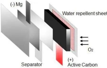
1.3.2 Magnesium alloy air cell (primary)
Fig. 1.3 Schematic diagram of Mg air battery
1.3.3 The introduction of the second battery of Mg battery
Magnesium is expected to provide one of the next generation negative battery active materials due to its high electrochemical energy capacity and no dendrite formation of electro-deposited of magnesium on changing, different with lithium ion batteries which employ carbon materials for the intercalation with lithium. Some combinations with positive active materials have been proposed for magnesium secondary batteries.
Fig. 1.4 Illustration of rechargeable magnesium battery
Fig. 1.5 Illustration of rechargeable Li ion battery
When the battery is charged, under the action of external voltage, magnesium ions remove from the cathode material, through the dissolution of the electrolyte, adsorption, transfer and other processes reach the anode, and the negative material deposition; discharge, the magnesium ions are removed from the negative, through the electrolyte back to the positive electrode. Magnesium from sub-respectively in the battery cathode and anode reduction, oxidation reaction, the battery system can be generated in the direction of movement Magnesium ions. Electrolyte solution as a bridge of magnesium ion migration, provide the necessary internal migration of magnesium ions. Due to the large charge density of magnesium, solvation serious, magnesium secondary battery research by the following aspects of the system
Lake of Magnesium: (1) Magnesium has a high chemical activity and tends to form a surface passivation film in most solvents. Magnesium ions are difficult to form through this dense surface film, the reversible deposition and dissolution of magnesium in the electrolyte become very difficult; (2) Magnesium ion charge density, serious solvation, it is difficult to embed in the general matrix, the choice of cathode material Subject to certain restrictions; (3) lack of mediators that mediate Mg2 +
.
The study team of the Yamaguchi University graduate school science and technology studies graduate course developed a magnesium battery with electric capacity of approximately of the used lithium ion battery now theoretically. It is expected that contribution to the mileage is expansion of the electric car. As for the rechargeable battery, anode materials (positive pole) and cathode materials (negative pole) which play a role as the fuel producing energy are comprised of three elements of a medium of the energy between the electrode and the electrolyte . To the rechargeable batteries such as the cell-phones which are generally used, an organic electrolyte use the lithium ion is used for artificial black lead (charcoal), electrolyte to a cobalt-based compound, cathode materials to anode materials mainly now. However, because cobalt and lithium were metals, production cost rose, and the problem for the further spread remained, too.
Because Mg2+ reacts with a cathode, the magnesium sulfur rechargeable battery is charged and is discharged electricity by reacting with an anode. Because the energy density can produce much energy with less quantity at approximately of the conventional lithium ion rechargeable battery, it is compact, and the manufacture of the lightweighted rechargeable battery is enabled. Furthermore, it is expected that development, the spread of large size batteries to use advances to EV or the solar panel because resources-like problem can be settled cost. Sulfur is a by-product occurring at the time of oil refining, and there is the merit to be able to the effectively utilize resources.
1.3.4 Effection of Vanadium Oxide inserted in Anode
electrochemistry of the nanocrystalline materials with microcrystalline V2O5 in order to accurately assess the effectiveness of this approach. The use of conductive materials has also been tested as a means of improving Mg2+ diffusion. When the electrochemical performance of a composite carbon –V2O5 xerogel was compared to that of an electrode prepared via a conventional mixture of V2O5, the composite exhibited a higher capacity.
1.3.5 Introduction of Magnesium stem cell
The magnesium stem cell uses a magnesium alloy for the negative electrode and the positive electrode uses manganese dioxide with acetylene black added to give conductivity. To increase the corrosion resistance, chromium salts of barium and lithium are added to the electrolytic solution, and an aqueous solution of magnesium perchlorate is added with magnesium hydroxide (pH 8.5) as a buffer to further improve the storage performance . This battery system has two features compared with manganese / zinc battery. That is, the capacity is doubled, and self-discharge is small even at high temperature. The reason why the storage performance is excellent due to the passive film formed on the surface of the magnesium negative electrode.
1.4 Electrochemical reaction principle
The performance of the battery has to meet various demands including not only the output (energy, capacity) but also operation environment and the electrical condition bottom [63]. Nowadays, the battery technology had accomplished progress a lot . The electrochemistry reaction system to join a cathode and an anode together at the same time is improved, and the battery based on a new principle has been developed, but an all-around battery showing superior performance under every condition does not exist again [64]. In order to get a battery of the higher performance, varieties of electrochemistry systems design and batteries development being continued. The battery of the special design is applied for military affairs or industry and is used in environment needing a specific function [65]. An ideal battery is cheap and, with infinite energy, can supply all output levels, and can work under the wide temperature range, and it must be the thing which be superior to the durability, and is also safe . However, there is really life because a chemical reaction and a physical change are caused in the case of preservation and the storage.Besides, as for the performance of the battery, it is acted on temperature and electric discharge speed.In addition, the use of energy storage materials to increase energy output density and a special design push up a price, and a problem in the physical security of the battery corresponds, in addition to this particularly, the prophylaxis is necessary. A study to draw the best performance is essential to choose a battery having highest performance in such a demand, and to use the battery definitely[66].
The device which converts chemical energy into electric energy by the electrochemic oxidation reaction and reduction reaction in the twin cathode and anode directly is a voltaic battery (including the fuel cell). One cell is comprised of a cathode (anode) which the anodal (cathode) reduction reaction that an oxidation reaction happens at the time of an electric discharge happens and the electrolyte that the electric charge transportation by the ion takes place .
this energy at the time of an electric discharge as electric energy, but has a loss due to various polarizations when load electric current i flows with an electrochemical reaction. I polarize activation to let a reaction progress on the surface of the ,① electrode for the thing included in these energy losses.②There is such concentration polarization due to the density difference of the reactants and products produced between the electrode surface and the bulk as a result of mass transfer. An important factor of greater its influence one the operating characteristics of the cell, there is an internal impedance which results in a reduction of the operating voltage, this is a waste of part of the effective energy as heat loss.
The cell voltage E when connected to an external load R can be expressed as the formula
E=E0-[(ηct)a+(ηc)a]-[(ηct)+(ηc)c]-iRi=iR
(1.1) Here, bottom additional character a,c with it out of the parenthesis shows anodal (cathode) cathodal (anode) each. In addition, E0 circuit voltage of the cell, ηct the activation polarization (charge transfer overvoltage), ηc is the concentration polarization (concentration overvoltage), i is the load current of the cell, Ri is the cell
internal resistance. As shown in equation 1.1, voltage that the cell can be effectively
generated is reduced by the amount by the minute and internal iRi drop due to polarization. Theoretically available energy batteries is determined by what cell or a chemical reaction occurs at the two electrodes, the influence factors are charging
transfer reaction rate, diffusion rate of the size and the size of the energy loss.Around
1.5 Corrosion reaction of the Battery
1.5.1 Electrochemistry corrosion
It is to include both chemical conjugation and electrical change, and the characteristic of the electrode reaction is one of the non-homogeneous system reactions. For an electrode reaction, there is the simple thing which only works on the reduction of metal ions in an electrode with a formed metal atom [67] .Even if a reaction is simple in an appearance, the mechanism of the process as a whole is complicated, and it is from the generally plural steps.Prior to an electronic movement process, and it is necessary for active excellent chemical species to be transported by migration or diffusion electrochemically to the electrode surface. In addition, the adsorption of the active kind may affect it on the electrode of the electronic movement process. Furthermore, a chemical reaction may be included in all electrode reactions. In the same way as a general reaction, the speed of the electrochemic process is ruled over consecutively among the reaction processes named the ream by the speed of the slowest step[68]. In the thermal mechanical handling of the electrochemical process, but to define the equilibrium conditions of the system, it cannot be foreseen in relation to non-equilibrium conditions, such as the current based on the polarization (overvoltage) to be added in order to cause a reaction. Examining the Current - overvoltage characteristics experimentally for many systems, it has been found that there is a linear relationship between the logarithm of current density i and the overvoltage η. Expression of this relationship which was generally described is Tafel.
η=a+blog|i|
(1.2)
Constant b is usually called Tafel coefficients. The relationship between the Tafel is
made of a wide range of overvoltage for many of the system. However, when
overvoltage is small, these relations are not managed, and the plot of η vs. logi is aberranted the straight line. [69-72]
An expression of Tafel was applicable to many experiments system well, and, in a
thing, the kinetics about the electrode reaction process progressed. Because the
could be considered that express electric current - overvoltage relations when rather a
process progresses in one is natural without applying to it in equilibrium.It means, for
example, that a re-reduction process for reverse is a negligible condition in the oxidation process.
i= (
(1.3)
In a more general theory, it is necessary to consider both forward reaction and inverse reaction about the simplified electrolysis reduction process such as Fig. 1.6[73,74]
Fig. 1.6 The simplified figure of reduction on the surface of electrode
As shown in this action
O+ne
-R
(1.4) Here, O is the oxidant, R represents reductant, n is the number of electrons
involved in the electrode reaction. Forward reaction can refer to the speed of the
inverse reaction using each speed fixed number kf, kb and is given in the product with
the speed fixed number and the density of reactant (appropriate using the density in
the electrode surface).[75]The density of active chemical species is not often equal to
the electrode surface in bulk solutions electrochemically. The speed of the forward
reaction is KfCo, while the reverse reaction is KbCR, these are usually transcribed in
current density if of the forward reaction, form of current density Ibof the inverse
reaction for convenience.
I
f=nFAkfCo
(1.5)I
b=nFAk
bC
R (1.6)Here A is the area of the electrode.
The type is not only the thing which expressed an original direction and the speed of the reverse electrode reaction process simply. It can be considered that the electronic ratio in the electrode reaction process if it can be regarded that the speed fixed number depends on the electrode potential. This dependence is usually expressed based on a supposition that remaining some (1-a) E contributes to restraint of the inverse reaction again aE which is a part of the overvoltage by promotion of the forward reaction.
kf=
(1.7)
k
b=
exp
(1.8)
Here, a is the transfer coefficient.[76,77] Because the electric current of the original taste does not flow in the equilibrium, As shown in this equation.
i
f=i
b=i
0 (1.9) In an expression (1.9) when substituted an expression (1.5) – (1.8) ,E
e=
(1.10)
The standard value E of the formula in potential with concentration rather than the activity of the reaction-participating material can be defined as the equation from (2.9) to(1.11).
=
ln
(1.11)
Ee=
+
ln
(1.12)
The standard electrode electric potential of magnesium calculated based on the above-mentioned expression is -2.37V, and the primary cell and the rechargeable batteries are the material which is attractive as cathode materials. In addition, from a Nernst type and the expression of the current density, mechanism of the magnesium corrosion became clear[78-80].
1.5.2 Application of the stress corrosion
The stress corrosion depends on tensile stress from the inside or the outside and synergism of the corrosion. The characteristic of the stress corrosion is that dissolves a corrosion product and may interfere with the generation of the passivity oxide film.
The generation of a wedge-shaped section by the anodal erosion, and new small anodal appearance occurs, and a process of the stress corrosion advances auto catalytically more, and the formation of the passivation oxide film is restrained, and erosion caused by the corrosion progresses[81]. It seems to show the stress corrosion in Fig. 1.7 schematically and occur when three persons of materials, environment and the stress meet in a specific condition.
Fig. 1.7 Stress corrosion and factors
When change ΔG(per g) of the free energy refers to relations of the stress in an expression (1.15).
ΔG=
(1.15)
Here ,δis the applied stress, Y is Young`s modulus,ρis the density of the Mg alloy. And the change of the electric potential is accompanied with a change of the free energy.
ΔE=-
(1.16)
Here, n is the electronic number, F of the reaction is the faraday fixed number[82].
Therefore, I show electric potential and relations of the stress in an expression (2.17) from expression (1.16), (1.17).
ΔE=-
(1.17) With the generation of the immovable oxide film, and using the stress corrosion method, the surface of the magnesium alloy can propel the reaction of the surface of the magnesium alloy and the solution. In addition, it can suppose that the voltage of the magnesium alloy electrode towards the negative direction under the influence of stress. It can be considered that it can improve the battery chemistry performance of the magnesium with the method of stress corrosion.
1.6 Design of magnesium electrode material
1.6.1 Selection of the added element of a new magnesium alloy
Usually, the magnesium electrode material the addition of trace elements, also has been developed to changes in manufacturing methods and conditions based Nuisance material design of the original, yet corrosion resistance and machinability and electricity further having a microstructure in accordance with the application purpose properties improvement and the chemical properties have been sought. Therefore, in this study, it was first investigated the information about the trace additive element. The conventional magnesium alloys Al, Zn, although Mn element is mainly added, considering the characteristics of the group metal element, as shown in Table 1.1, the characteristics of the magnesium alloy is affected by the addition of another element[83].
Table 1.1 Influences of alloying elements on the properties of Mg alloys
microporosity hardening at low temperature Be Significantly reduces oxidation of melt surface at very low concentrations lead to coarse grains Improve creep properties Ca Effective grain refining effect,slight suppression of oxidation of the molten metal Detrimental influence on corrosion behavior
Cu System with easily
forming metallic glasses, Improves castability Detrimental influence on corrosion behavior, limitation necessary Fe Magnesium hardly
reacts with mild steel crucibles Detrimental influence on corrosion behavior, limitation necessary In Improves castablitity, tendency to microporosity Improves elevated temperature tensile and creep properties, improves ductility, most efficient alloying element Improve corrosion behavior
evaporation and burning behavior, melting only in protected and sealed furnaces hardener at ambient temperatures, reduces density, enhances ductility corrosion properties strongly, coating to protect from humidity is necessary Mn Control of Fe content by precipitating Fe-Mn compound, refinement of precipitates Increases creep resistivity Improves corrosion behavior due to iron control effect
Ni System with easily
forming metallic glasses
Detrimental influence on corrosion behavior Rare earth Improve castability,
reduce microporosity
Solid solution and precipitation hardening at ambient and elevated temperatures Improve corrosion behavior Sn Suppresses microporosity Improves elevated temperature tensile and creep properties, improves ductility, most efficient alloying element Improve corrosion behavior Y Grain refining effect Improves elevated temperature tensile and creep properties Improve corrosion behavior
the melt, weak grain refiner, tendency to microporosity hardening, improves strength at ambient temperature, tendency to brittleness and hot shortness unless Zr refined sufficient Zn content compensates for the detrimental effect of Cu Zr Most effective grain refiner, incompatible with
Si, Al, and Mn, removes Fe, Al, and
Si from the melt
Improves ambient temperature tensile
properties slightly
Among general-purpose pure magnesium and magnesium alloy AZ31, AZ91, AZ91 alloy is most used as a magnesium product. The reason is that it has excellent castability (moldability), high strength and high corrosion resistance.In addition, the results of comparing electrochemical performances of pure magnesium AZ31 and AZ91 alloy are that AZ91 has higher voltage and stable current. Therefore, in this study, based on the AZ91 alloy, a new magnesium alloy was developed by adding trace elements.The components of AZ91 alloy are shown in Table 1.2.
Table 1.2 Ingredient of AZ91 alloy
Al Zn Mn Si Fe Mg
AZ91 9.0 0.8 0.22 0.04 0.001 balance
Compound MnS which can improve the performance of AZ91 alloy and designed the manufacturing experiment of Mg - Zn - In - Sn - MnS alloy.
1.7 Purpose of this study
Because we had performance such as the recyclability that magnesium was an abundant resources material, and was eco-friendly, so it has been attracted attention as effect materials for a long time. In addition, the magnesium electrode is expected as attractive new energy because it has a low higher cost theory capacity, high energy density and a long-term storage life.
In this study, it has been used of superior performance of magnesium and developed a new magnesium alloy electrode available as an eco-energy source in a generation in sequence. In addition, I succeeded that in improving the electrochemistry performance of the new magnesium alloy electrode by using corrosion promotion action of the stress to find more high efficiency. Furthermore, using the new magnesium alloy electrode, a new magnesium air cell (primary cell) and the secondary battery would be tried to development. Furthermore, by applying stress, ecological problems can also be improved, for example recovery of phosphorus.
1.8 Composition of this paper
This research consists of 8 chapters.
Chapter 2 A new magnesium alloy was produced. By the observation of the fine structure, the action of the additive element is described. Furthermore, from the viewpoint of practical application, workability and corrosivity of the magnesium alloy electrode were studied.
Chapter 3 In order to improve the electrochemical performance of the alloy electrode, stress was applied to examine the performance of the alloy. Furthermore, by using various electrolytic solutions, the electrochemical performance of the novel magnesium alloy electrode was investigated by the influence of stress corrosion. Corrosion model of magnesium alloy electrode was developed based on the basic principle of stress corrosion method. Also, manganese ions in the solution were simulated using discharge reaction. Furthermore, the voltage and current of the novel magnesium alloy electrode were calculated.
Chapter 4 When stress corrosion is applied, the effect of electrochemical corrosion becomes clear. Based on the principle of stress corrosion, primary batteries are being developed.
Chapter 5 The effect of Magnesium alloy electrodes under tensile stress were examined for magnesium secondary batteries. Besides the charge and discharge performance, the effect of tensile stresses was confirmed by cyclic voltammetric measurements and SEM observations.
Chapter 6 A practical method was studied for phosphorous resource recovery from wastes, such as waste water or many kinds of sludge. It was confirmed that the magnesium alloy electrodes could remove phosphates from the sludge and dissolute them by applying tension stress for phosphate resources recovery.
1.9 Conclusion
(1) The battery discharges by a chemical reaction, and the voltage can be calculated with the Nernst equation.
(2) It can be inferred that the electrochemical performance of the battery using the principle of stress corrosion can be improved.
(3) For the magnesium alloy, we examined the advantages and disadvantages of each element and clarified the effect of the added element to the magnesium alloy.
Reference
[1] M.Barak.Electrochemical Power Sources-Primary&Secondary Batteries, Peter Peregrinus, Stevenage, U.K.,1980
[2] B.E.Conway.Theory and Principles of Eletrode
Processes,Ronald,NewYork,1965.
[3] H.Bode.Lead-Acid Batteries (translated from German by R.J.Brodd and K.V.Kordesch), Wiley, New York,1977.
[4] D. H. Dorghty, B. Vyas, T. Takamura and J. R. Huff, Materials for ELECTROCHEMICAL Energy storage and Conversion-Batteries, Capacitors and Fuel Cells, Materials Eeseach Society, Pittsburgh,1995
[5] S.U.Falk and A.J. Salkind.Alkaline Batteries, Wiley, New york,1969.
[6] A.Fleischer and J.J lander.Zinc-0Silver Oxide Batteries, Wiley, New York,1971
[7] Frost and Sullivan Inc,U.S.Market for Batteries, Summer 1992.New York,1992
[9] The Freedonia Group,Inc.,Industry Study 395, Primary and Secondary Batteries,Cleveland,Ohio,Jan.1992
[10] R.Samuel,The Evolution of Electric Batteries in Response to Industrical Needs,Dorrance, Philadephia,1978
[11] V,George, rimary Batteries, Wiley, New York,1950
[12] N.C.Cahoon and G.W, Heise, The primary Battery,Wiley, New York,1976.
[13] H.Richard, Batteries, Dekker, New York,1974
[14] A.Kozawa and R.A.Powers,Electrichemical Reactions in Batteries,J.Chem. Ed. 49(1972):587
[15] R.J.Brodd, A.Kozawa, and K.V, Kordsh, Primary Batteries 1951-1976, J.Electrochem.Soc.7(1978);125
[16] M.Bregazzi, Electrochem, Technol., (1967):507.
[17] C.L.Mantell, Batteries and Energy Systems, McGraw-Hill,New York,1983.
[18] American National Standard Speccifacation for Dry Cells and Batteries, ANSI C18.1-1992, Amricaqn National Standard Institute, New York, 1992.
[19] Everyday Battery Engineering Data, Everyday Battery Company, St.Louis, Mo., 1992
[20] M.Dentch and A.Hillier, Progress in Batteries and Solar Cells,Polaroid Corp., 1992
[21] NEDA Batteries Index,National Electronic Distributors Association, Chicago, 1990
[22] A.J.Salkind, D.T.Ferrell, and A.J.Hedges, Secondary Batteries 1952-1977, J.Electrochem. Soc. 8(1978):125
[23] A.J.Salkind, Director,Battery Laboratory, Rutgers University, NJ,1994
[25] L.H.Thaller, Expected Cycle Life vs.Depth of Discharge Relationships of Weii-Behaved Single Cells and Cell Strings,J.Electrochem.Soc.5(1983):130 [26] R.Udhayan and B.D. Prakash. On the corrosion behavior of magnesium and its
alloys using electrochemical techniques[J], J Power Sources, 63(1996):103 [27] E.J.Wade, Secondary Batteries, The Electrician, London, 1902
[28] M.Barak(Ed), Electrochemical Power Source, Peter Pereginus, London,1980
[29] P. Ruetschi, J. Power Source 42(1993):1.
[30] F.J.Kruger,J.Russow,G.Sandstede (Eds.), Proceedings of the Annual Meeting of the GDCh-Monographie 12(1998):250
[31] L.F.Trueb,P.Ruetschi,Batterien and Akkumulatoren, Springer-Verlag, Berlin, Heidelberg, New York, 1998
[32] D.Berndt, Maintenance-Free Batteries, Wiley, New York, 1993
[33] J.L. Fricke and H.A.Kiehne, Batterien, in’F.J.Kruger,J.Russow,G.
Sandstede(Eds),Proceedings of the Annual Meeting of the GDCh-Fachgruppe Angewandte Elektrochemie in Vienna,9,1997, GDCh-Monographie 12(1998):
472
[34] D.Linden (Ed.), Handbook of Batteries, second ed., McGraw Hill, New York 1995
[35] F.Beck, K.J. Euler, Elektrocheemische Energiespeicher, VDE-Verlag, Berlin and Offenbach,1984.
[37] F.Beck(Ed.), Elektrochemie der Elektronenleiter-Metalle, Oxide, Polymere, Proceedings of the Annual Meeting of the GDCh-Fachgruppe Angewandte Elektrochemie in Duisburg, 9, 1995, GDCh-Monographie 3(1996).
[38] C.F. Holmes and A.R.Landgrebe(Eds), Batteries for Portable Applications and Electric Vehicles, Proceedings 48th ISE-Meeting;192nd ECS-Meeting, Paris,9, 1997, The Electrochem. Soc., Pennington, NJ(1998).
[39] S.C.Levy and M.E.Fiorino, Electrochem. Soc.Interface Winter 5(1995):26 [40] G.Kortum, Lehrbuch der Elektrochemie, fifth edition, Verlag Chemie,
Weinheim, 37(1972):551.
[41] R.P.Clark, J.L. Chamberlin, H.J. Saxton and P.C. Symons, Power Sources 9, Academic Press, London, 1983
[42] A. Heinzel, M. Zedda, U. Paschke and M.Barragan, D. Golombowski,
Extended Abstracts 50th ISE Meeting, Pavia 9, 1(1999):887 [43] K.J. Vetter, Chem.-ing.-Techn.45(1973):213.
[44] M.S. Whittingham,J.Electrochem Soc.123(1976):315. [45] B. Scrosati, J. Electrochem. Soc. 139(1992): 2276
[46] H.A.Liebhafsky, Regenerative EMF Cells, in; C.E. Crouthamel, H.L. Recht(Eds.), Advanced Chemistry Series, Washington 64(1967).
[47] L.L. Swette,A.B. Laconti and S.A.Mc Catty, J.Power Sources 47(1994):
343.
[48] J. Giner, A.B. Laconti, New Promisingn Electrochemical Systems for Rechargeable Batteries, in; V.Barsukov, F.Beck(Eds.), Proceedings of the NATO Advanced Research Workshop, Puscha Voditsa near Kiev, Ukraine, May 14-17, 1995, Kluwer Academic Plublishers, Dordrecht(1996):215
[50] J.Barthel, H.J.Gores,Batterien, in; F.J. Kruger, J.Russow,G. Sandstede (Eds.), Proceedings of the Annual Meeting of the GDCh-Fachgruppe, Angewandte Elektrochemie in Vienna, 9, 1997, GDCh-Monographie 12(1998):185
[51] P.Ruetschi, J.Elkectrochem.Soc.139(1992):1347
[52] E.Bashtavelova,A.Winsel, in; F.J.Kruger, J.Russow, G.Sandstede(Eds.),
Proceedings of the Annual Meeting of the GDCh-Monographie 12(1998): 121 [53] H.D. Yoo, I. Shterenberg, Y. Gofer, G. Gershinsky, N. Pour, D. Aurbach,
Energy Environ. Sci. 6(2013): 2265
[54] P. Novak, R. Imhof, O. Haas, Electrochim, Acta 45(1999) :351-367
[55] Z. Lu, A. Schechter, M. Moshkovich, D. Aurbach, J. Electronal. Chem. 466(1999)203-217
[56] D. Aurbach, Z, Lu, A. Schechter, Y. Gofer, H. Gizbar, R. Turgeman, Y. Cohen, M.Moshkovich, E. Levi, Nature(Lond.)407(2000)724-727
[57] G. G. Amatucci, F. Badway, A. Singhal, B. Beaudoin, G. Skandan, T. Bowmer, J. Pitz, N. Pereira, T. Chapman, R. Jaworski, J. Electrochem. Soc. 148(2001) :A940
[58] L. Jiao, H. Yuan, Y. Si, Y. Wang, J. Cao, X. Cao, M. Zhao, X. Zhou, Y. Wang, J. Power Sources 156(2006):673-676
[59] L. Jiao, H. Yuan, Y. –C. Si, Y.-J. Wang, Electrochem. Commun, 7(2005):
431-436
[60] L.-F.Jiao,H.-T.Yuan, Y.-C.Si,Y.-J.Wang, Y,-M.Wang, Electrochem. Commun. 8(2006):1041-1044
[61] F.Beck, J.Elecrochem. Soc.129(1880): 1982.
[62] T.J. Clough, R.L. Scheffler, Extended Abstract, 9th Battery and Electrochem.
Contractors Conference(DOE),11,1989, US Department of
[63] J.P.Gabano, Lithium Batteries, Academic Press, London, 1983.
[64] R.W.Gabam, Secondary Batteries-Recent Advances, Noyes Data Corp,Park Ridge, N.J., 1978
[65] H.A.Kiehne, Battery Technology Handbook, Kekker, New York, 1989.
[66] K.V.Kordesch, Manganese Kioxide, vol.ll leak-Acid Batteries and Electric Vehicles, Kekker, New York,1974 and 1977
[67] C.L.Mantell, Batteries and Energy Systems, McGraw-Hill, New York,1983
[68] G. Pistoia, Lithium Batteries, Elsecier, New York, 1950
[69] H.V. Venkatasetty, Lithium Battery Technology, Wiley, NewYork, 1984
[70] G.W.Vinal, Primary Batteries, Wiley, NewYork,1950
[71] Proceedings of the Annual Battery Conference on Applications and Advances, California State University, Long Beach, Calif, 1996.
[72] Proceedings of the 23rd Intersociety Energy Conversion Engineering Conference, American Chemical Society, Washington, D, C, 1988
[73] Electric Batteries, a Bibliography, Energy Research and Development Administration, Report no. TID-3359, Washington,1977
[74] Fuel Cells, a Bibliography, Energy Research and Development Administration, Report no.TID-3359,Washington,1977
[75] Batteries,Fuel Cells, and Related Electrochemistry, Books, Jounals, and Other Information Sources,1950-1979, U.S. Dept. of Energy Rep.DOE/CS-0156, Washington, D.C.,1980
[76] Feel Cells, A Handbook, U.S. Department of Enerty Rep.DOE/METC-88/6096, Washington,D.C.NASA Handbook of Nick-Hydrogen Batteries, NASA Ref.Pub.1314, Sept.1993.
[78] Navy Primary and Secondary Batteries-Design and Manufacturing Guidelines, Department of the Navy Publ. NAVSO P-3676, Sept.1991.
[79] NAVSEA Battery Document; State of the Art, Research and Development, Projections, Environmental Issues, Safety Issues, Degree of Maturity, Department of the Navy Publ.NAVSEA-AH-300, July 1993
[80] M. Barak, Electrochemical Power Sources-Primary and Secondary Batteries, Peter Peregrinus, Stevenage, U.K.,1980
[81] H.Bode,Lead-Acid batteries(translated from German by R. J. Brodd and K. V. Kordesch), Wiley , New York, 1977
[82] B.E. Conway, Theory and Principles of Electrode Processes, Ronald, New York,1965
[83] R. W. Cahn, P. Hassen and E. J. Kramer, Materials science and technology structure and properties of nonferrous alloys, UCH, New York, 1996
Chapter 2 Development of magnesium alloy electrode
materials and performance evaluation
2.1 Production of the Mg-Zn-In-Se-MnS alloy
2.1.1 Vacuum gas replacement furnace
Magnesium is a chemically active metal and reacts with oxygen in the atmosphere, so ordinary metal mapping furnace can not be considered as casting magnesium alloy. Therefore, in order to prevent oxidation of the magnesium alloy during melting, casting experiments were carried out using a vacuum gas replacement furnace in this study. Figure 2.1 shows a vacuum gas replacement furnace SM - 1300. First, the interior of the furnace is evacuated with a directly connected oil rotary vacuum pump, then argon gas is injected to prevent oxidation when the metal dissolves[1]. By controlling with the program PID device, the maximum temperature in the furnace reaches 1300 ° C.
2.1.2 Fabrication of Mg-Zn-In-Sn-MnS alloy in vacuum gas
replacement furnace
AZ91 alloy and additive element Zn - In - Sn - MnS were placed in a crucible and placed in a vacuum gas replacement furnace.After this, the furnace was closed and a vacuum was applied before argon gas was added.The casting temperature is set with the program PID control device, the maximum temperature is 680 ° C., the heat retention time is 1 hour. Finally, the inside of the furnace was lowered to room temperature, and a new magnesium alloy Mg - Zn - In - Sn - MnS was produced.
2.2 Production method of magnesium alloy plate
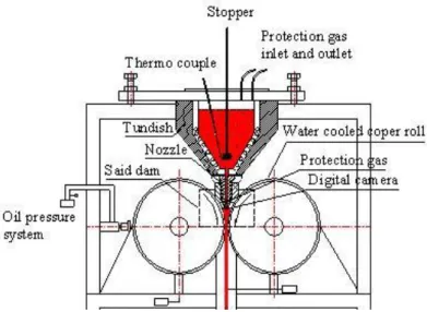
2.2.1 Twin-roll continuous casting
About 50 years have elapsed since the continuous casting and rolling process (cc) was introduced into the aluminum industry, but various methods were developed, various improvements were added, the productivity and product quality were improved, Production volume of thin plates by year increased, and in 1970 it was only 10% of the general DC casting route, but it increased to 30% in 2002[2-5].
Fig. 2.2 Overview of pilot vertical twin roll caster
2.2.2 Manufacture of the Mg-Zn-In-Sn-MnS alloy sheet
A figure of structure of the pilot vertical twin roll continuous casting machine is shown in the Fig. 2.3. The sheet casting process of the magnesium alloy is the phenomenon that is very complicated other than a simple physical change. At first AZ91 alloy and additional element Zn-In-Sn-MnS were mixed in tundish well and the tundish project was controlled and heated up. And it is flowed into the lower oil tank through the twin roll that the liquid which dissolved turns by the tundish. Two shells which hardened go along the place to thicken from the smallest gap of the roll.[7-12].
2.3 Analysis of the magnesium alloy ingredient
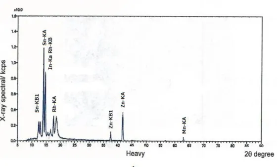
2.3.1 Fluorescence X-rays analysis of the magnesium alloy ingredient
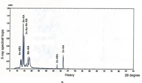
Mg-Zn-In-Sn alloy and Mg-Sn-In-Sn-MnS alloy ingredient were measured by fluorescence X-rays. Figure 2.4(A) and Fig. 2.4 (B)show a spectrum of the fluorescence X-rays qualitative analysis of Mg-Zn-In-Sn alloy and the Mg-Zn-In-Sn-MnS alloy.Elemental peaks such as Al, Mn, Zn, Sn, and In appeared clearly to show it in Fig. 2.4(B) and were able to confirm that an additional Mn element existed in Mg-Zn-In-Sn-MnS alloy.
Fig. 2.4(B) Fluorescence X-rays ingredient of Mg-Sn-In-Sn-MnS alloy
2.4 Performance evaluation of Mg-Zn-In-Sn-MnS alloy
2.4.1 Observation of fine structure
The fine structure of the Mg - Zn - In - Sn alloy and the Mg - Zn - In - Sn - MnS alloy which were casted by twin roll continuously and was observed by using OM ,the photograph is shown in Fig. 2.5. Although Mg - Zn - In - Sn has a grain boundary size of 20-100 μm, Mg - Zn - In - Sn - MnS has a grain boundary size of about 5-10 μm and is found to be extremely small
Fig. 2.5 Observation of fine structure of (a) Mg - Zn - In - Sn and (b) Mg - Zn - In - Sn - MnS
100μm a
2.5 Experiment of tensile stress
A thin plate having a thickness of 0.5 mm was produced from a sheet material having a thickness of 3 mm by casting. According to the dimensions of the specimen, the tensile specimens prepared are shown in the Fig. 2.6. The test piece size is 70 mm in total length, the length of the reference point part is 26 mm, and the mark part width is 6 mm. The plate has been designed and produced. Using the tensile testing machine the experiment can be measured.
Fig. 2.6 Specimen of Stress-strain Experimentation
2.6 Conclusion
In this chapter, a new magnesium alloy Mg - Zn - In - Sn - MnS is prepared by adding a trace element Mn to a magnesium alloy Mg - Zn - In - Sn using a vacuum gas replacement furnace and made it by twin roll continuous casting method. Components of the Mg - Zn - In - Sn alloy were analyzed using fluorescent X-ray. Furthermore, the microstructure of the prepared Mg - Zn - In - Sn - MnS alloy and the Mg - Zn - In - Sn alloy were compared to clarify that the performance of the Mg - Zn - In - Sn - MnS alloy was excellent.
Reference
[2] T.Haga et al,High Speed Roll Casting of Aluminum Alloy Strip,Materials Science Forum.475(2005):343
[3] T.Mizoguc et al, Relation between Surface quality of as-Cast Strips and Meniscus Profile of Molten Pool in the Twin Roll Casting Process, ISIJ International, 36(1996):417
[4] L. Strezov and J. Herbertson, Experimental Studies of Interfacial Heat Transfer and Initial Solidification Pertinent to Strip Casting, ISIJ International,38(1998):959
[5] B.Sun,Characterization of Magnesium Plates Produced by Wheel-band Casting and Horizontal Continous Casting, materials Science Forum. 488(2007):337
[6] O.Daland et al,Thin Gauge Twin-roll Casting Process Capabilities and Product Quality, Light Metals, 23(1997):745
[7] G.Z.Doing, Research on microstructure and properties of highly strengthened wrought magnesium alloys[D],Chongqing;Chongqing University,2005
[8] E.F.Horst and B.L.Mordike, Magnesium technology, metallurgy, design data, application[M].Berlin, Heidelberg; Springer-Verlag,2006
[9] G.Abbas,L.Li,U.Ghazanfar ang Z.liu, Effect of high power diode laser surface melting on wear resistance of magnesiumu alloys[J].Wear, 260(2006):175 [10] F.W.Bacha and M.Rodmanb, High quality magnesium sheets for automotive
applications[J].Advanced Materials Reasearch, 6(2005):665.
[11] A.J.Carpenter, Automotive Mg research and development in North America [J].Materials Science Forum,546(2007):11
Chapter 3 Evaluation of electrode performance with stress
corrosion and clarification of electrochemical · stress
corrosion mechanism
3.1 Advantages and mechanisms of manganese sulfide
A convenient hydrothermal synthetic route has been successfully developed to prepare stable rock-salt-type structure α-MnS submicrocrystals under mild conditions. In this synthetic system, hydrated manganese chloride (MnS) was used to supply a highly reactive manganese source. The results revealed that the electrochemical performance of the MnS submicrocrystals may be associated with the degree of crystallinity and particle size of samples. The initial lithiation capacity of the MnS
submicrocrystals obtained is 1327 mAh g−1 at 1.7 V versus Mg/Mg2+, which exhibited
αMnS submicrocrystals is extremely promising anode material for magunesiumu-ion batteries and has great potential applications in the future. MnS has a large
electrostatic capacity. But also has a storage container for batteries.
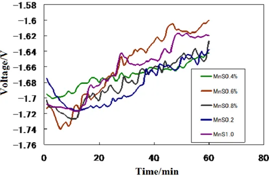
Fig. 3.1 The comparison of voltage value of a variety
Fig. 3.2 The comparison of voltage value of a variety of MnS concentration in Mg-Zn-In-Sn-MnS alloys.
MnS had added into the Mg-Zn-Sn-In alloy as 0.2%,0.4%,0.6%,0.8%,1.0%.The alloy of 0.8% showed the best excellent electrochemical effect of all, both from the current value or stability, as shown in Fig. 3.2 .
3.2 Electrolyte selection and stress corrosion experiment
In this section the two electrolytes and the four loading forces have been set up, and the distance between the cathode and the anode are also distinguished. Here, we use the best electrochemical properties alloy Mg-Zn-In-Sn-MnS which the containing of manganese sulfide was 0.8% for testing. The two electrolytes were 1mol / L ACONa and 1mol / L KCl solution, respectively. The forces applied were 0N, 50N and 100N. The distance between the cathode and the counter electrode is also divided into 10 mm and 2 mm.
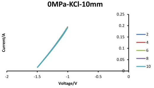
3.2.1 CV curve of KCl from 0 Mpa to 10 MPa at a distance of 10 mm
Fig. 3.4 CV curve of KCl for 3.3Pa at 10mm
Fig. 3.5 CV curve of KCl for 10MPa at 10mm
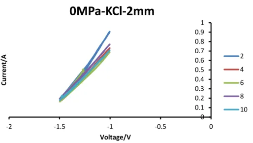
3.2.2 CV curve of KCl from 0 MPa to 10MPa at a distance of 2 mm
Fig. 3.6 CV curve of KCl for 0MPa at 2mm
Fig. 3.8 CV curve of KCl for 10MPa at 2mm
3.2.3 CV curve of AcONa from 0 MPa to 10 MPa at a distance of 10
mm
Fig. 3.10 CV curve of AcONa for 3.3 MPa at 10mm
Fig. 3.11 CV curve of AcONa for 10 MPa at 10mm
Fig. 3.12 CV curve of AcONa for 10 MPa at 2mm
Fig. 3.14 CV curve of AcONa for 10 MPa at 2mm
When the distance of the cathode and anode of 10 mm, electrochemical properties were confirmed to be high in top current value is large for KCl. When the distance of the cathode and anode was 2 mm, was found to have high electrochemical characteristics large, top current value of AcONa. In the same type of electrolytic solution, 2mm of the distance of the cathode and anode was higher than 10 mm. All together with the raise of the whole stress, top current value has been confirmed with the increase much more. Electrochemical performance became higher.
3.3 The theory of electro-chemical chemistry and the application
of the theory of the value of the study
3.3.1 Introduction
In recent years, magnesium alloy is expected to be applied to many batteries as a negative electrode material. Among the magnesium alloys, AZ91 is one of the alloys with excellent machinability and electrochemical performance[1]. According to previous studies, we have added the compound MnS with Mg-Zn-In-Sn alloy and developed a novel electrode material Mg-Zn-In-Sn-MnS alloy. It was confirmed by the additive element that the Mg - Zn - In - Sn - MnS alloy electrode exhibited a negative voltage and a higher current than the Mg - Zn - In - Sn alloy[2]. In addition, it was possible to further enhance the electrochemical performance of the Mg - Zn - In - Sn - MnS alloy electrode by using the stress corrosion method. Therefore, it was found that the interaction between stress corrosion and electrochemical corrosion improves the electric performance of the magnesium alloy.
However, theoretical electrochemical calculations on stress corrosion of alloy electrodes are generally difficult.
In this study, we measured the concentration of magnesium ions in the corrosion solution using ICP equipment and calculated the voltage and current of the Mg - Zn - In - Sn alloy electrode by FACSIMILE software. FACSIMILE software is a program that models complex chemical reactions and can simulate efficiently[3,4].Specifically, the reaction rate of magnesium and water was measured by an ICP apparatus and the effect of stress corrosion was investigated. In addition, the change in magnesium ion (Mg +) concentration were simulated for 1 hour by the reaction rate during stress corrosion. Then, the voltage and current of the alloy electrode were calculated and the mechanism of stress corrosion was analyzed.
Using the twin-roll continuous casting method, trace elements Zn, In, Sn, MnS were added to the AZ alloy to prepare an Mg - Zn - In - Sn - MnS alloy. The alloy plate was rolled to 0.5 mm and subjected to a heat treatment at 400 ° C. for 1 hour.
The magnesium alloy negative electrode was cut as 10 cm long, 1 cm wide, and 1 mm thick. The effective electrode area was limited to 1 cm2 by covering the electrodes using PVC spacers with a tetragonal hollow structure.
3.3.3 Measurement of Mg concentration
After conducting the stress corrosion experiment, the Mg2+ concentration was measured with an ICP apparatus. Calibration curves were prepared using magnesium ion and manganese ion standard solutions of 10,20 and 30 ppm. ICP spectra of each concentration were measured using standard equations, and the results are shown in Fig3.15.
y=0.564x +0.0001
(3.1)Fig. 3.15 Standard curve of Mg and Mn concentration
Based on the calibration curve, stress corrosion experiment was conducted, and Mg2+ concentration was measured. Then, the change of Mg2+ concentration during 1 hour was simulated by FACSIMILE by the reaction rate.
3.3.4 Proposal of hybrid model
We also proposed a hybrid model of electrochemical calculation using the reaction of magnesium and water. The corrosion reaction of the magnesium alloy follows the overall reaction formula 3.2.
Mg(s)+2H
2O(l) Mg(OH)
2(s)+H
2(g)
(3.2)
Calculated by the Mg concentration measured by the reaction rate ICP. Changes in Mg concentration during 1 hour were simulated by FACSIMILE software. The voltage and current model of the alloy electrode were prepared based on the change in the reaction rate and Mg concentration.
3.3.5 Mg2+ concentration changes
The Mg2+ concentration after 1 hour stress corrosion experiment is shown in Table 3.1. The Mg2+ concentration in the corrosive solution decreased with increasing stress. It was confirmed that the corrosion reaction of the Mg - Zn - In - Sn - X alloy electrode was promoted by the influence of the tension stress.
Table 3.1 Mg2+ concentration values after stress corrosion
Tension
Stress(MPa)
0
5
10
50
100
Mg2+ concentration(mol/L)0.0361
0.00592
0.00441
0.00312
0.00194
corrosion products were generated, and the Mg concentration in the corrosive liquid was slightly higher.
3.3.6 OCP calculation
The applied stress energy improved the electrochemical potentials of alloy anode, and persisted together with stresses, because the stress did not exceed the elastic limit. The change in free energyΔG(per g)is given by Equation(3.3)[5]
ΔG=
(3.3)
Where δis the applied stress, Y is Young’s modulus, and ρis the density of the
Mg-Zn-In-Sn-X alloy. The free energy of Mg-Zn-In-Sn alloy anode increased with the applied stresses increased. The negative removal of voltage ΔE was calculated in energy using Equation (3.4)[6,7].
ΔE=-
(3.4)
Fig. 3.16 Comparison of OCP curves for Mg-Zn-In-Sn-MnS alloy anode under stress corrosion 0MPa; 5MPa; 10MPa; 50MPa; 100Mpa
The OCPs were calculated by the following Equations(3.5)
E=E
0+
ln
(3.5)
Where E0 is the equilibrium potential for this reaction, F is Faraday constant, R is gas constant,[Ox]is the concentration of oxidant, and [Red] is the concentration of reductant. The calculation values of OCP are consistent with experimental results as shown in Fig. 3.16. However, the calculated value is different from the measured value. This finding can be attributed to the interference of environmental factors, such as the forming of corrosion product film and pH value of solution [9].
3.3.7 LC calculation
The LCs were calculated by introducting correction factor A to modify the expression of corrosion current density .Therefore, the LC density was expressed using Equations(3.4) and(3.5): Ai0
and
x=
︱ ︱︱ ︱
(3.7)
Where i (0) is the experimental current density, ba and bc are the anode and cathode Tafel constants, and E0 is the equilibrium potential of the reaction calculated from the Nernst equation. This is calculated by Equation (3.8). The expression of the corrosion current density is modified by introducing the correction factor A to calculate the LC.
I =
︱ ︱ ︱ ︱ – ︱ ︱ ︱ ︱ ︱ ︱ (3.8)Where is the experimental current density, and are the anodic and cathodic Tafel constants, and is the equilibrium potential for this reaction as computed from the Nernst equation, respectively.
Using equation (3.8), the current densities are calculated density under different stress corrosion conditions of 0,5,10,50 and 100MPa,respectively. And the LCs are calculated by the equation(3.9)
I=S×i (3.9)
Where I is the calculation current, S is the surface area of alloy anode.Tafel factors increased. The modified model of the LC verifies the reliability of experimental results[10-12].
Fig. 3.17 Comparison of LC curves for Mg-Zn-In-Sn-X alloy anode under stress corrosion 0MPa; 5MPa; 10MPa; 50MPa; 100Mpa
3.4 Conclusion
In this chapter, it was found that Mg - Zn - In - Sn - MnS alloy has the most negative rest potential by measuring various alloys in the same electrolyte.Furthermore, using the constant stress corrosion method, the CV curve of the new magnesium alloy was measured in various solutions. When the distance between the cathode and the counter electrode was 2 mm, it was confirmed that the output performance of the novel magnesium alloy was the highest under 1 MPa stress in 1 Mol AcONa solution.
A corrosion model was developed and the electrochemical properties of the Mg - Zn - In - Sn alloy electrode were calculated. The mechanism of stress corrosion was investigated and the following conclusions were obtained.
1) It was found that the concentration of Mg decreases as the stress increases.
3) By adjusting the Tafel coefficient, the calculation value of the alloy electrode current almost agrees with the experiment value. The relationship between stress and Tafel coefficient was clarified.
Reference
[1] Z. Yu, D. Y. Ju, H. Y. Zhao, and X. D. Hu, Journal of Environmental Sciences.23(2011):95
[2] Z. Yu, H. Y. Zhao, X. D. Hu, and D. Y. Ju, Transactions of Nonferrous Metals Society of China. 20(2010):318
[3] T. D. Gregory, R. J. Hoffman and R. C. Winterton, Journal of Electrochemical Society. 137(1990): 775
[4] D. D. Macdonald, Science. 48(1992):194.
[5] Y. B. Unigovski, L. Riber, and E. M. Gutman, Journal of Metals, Materials and Minerals. 17(2007):7.
[6] T. Shibata, Journal of the Society of Materials Science. 55(2006):979.
[7] P. L. Bonora, M. Andrei, A. Eliezer and E. M. Gutman, Corrosion Science. 44(2002): 729
[8] M. Clarke, Corrosion Science. 10(1970):671
[9] Y. B. Unigovcki, L. Riber, and E. M. Gutman, J. Metals, Mater. Minerals. 17(2007): 7.
[10] T. Shibata, J.Soc. Mater. Sci.. 55(2006): 979
[11] P. L. Bonora, M. Andrei, A. Eliezer and E. M. Gutman, Corr. Sci.. 44(2002):729