宇宙航空研究開発機構研究開発資料
JAXA Research and Development Memorandum
「ISO 11227 Space systems ー Test procedure to evaluate
spacecraft material ejecta upon hypervelocity impact
(宇宙システムー超高速度衝突に起因する宇宙機材料イジェクタ
評価のための試験手順)」
に基づく試験装置較正及びejecta評価試験
赤星 保浩,松本 晴久,北澤 幸人
2016年3月
宇宙航空研究開発機構
Japan Aerospace Exploration AgencyISSN 1349-1121 JAXA-RM-15-008
宇
宙
航
空
研
究
開
発
機
構
研
究
開
発
資
料
ࠕ
ISO 11227 Space systems
̿
Test procedure to evaluate
spacecraft material ejecta upon hypervelocity impact
㸦Ᏹᐂࢩࢫࢸ࣒
̿
㉸㧗㏿ᗘ⾪✺㉳ᅉࡍࡿᏱᐂᶵᮦᩱࢪ࢙ࢡࢱ
ホ౯ࡢࡓࡵࡢヨ㦂ᡭ㡰㸧ࠖ
ᇶ࡙ࡃヨ㦂⨨㍑ṇཬࡧ
ejecta
ホ౯ヨ㦂
㉥ᫍ㻌 ಖᾈ
㻖㻝䠈ᯇᮏ㻌 ᬕஂ
㻖㻞䠈⃝㻌 ᖾே
㻖㻟㻌
ᴫ
ᴫ せせ
ejecta(ࢪ࢙ࢡࢱ㸧ࡣࢫ࣮࣌ࢫࢹࣈࣜࡸ࣐ࢡ࣓ࣟࢸ࢜ࣟࢻࡀᏱᐂᶵ⾲㠃㉸㧗㏿⾪✺ࡍࡿ㝿
ḟⓗ⏕ࡌࡿࢹࣈ࡛ࣜ࠶ࡾࠊPaint flakes࡞ࡽࢇ࡛ᚤᑠࢧࢬࡢࢹࣈࣜࡢ㔜せ࡞Ⓨ⏕※⪃࠼ࡽࢀ࡚࠸
ࡿࠋᅜ㝿ᶆ‽ᶵᵓ㸦ISO)ࡣ2012ᖺᅜ㝿ᶆ‽ᩥ᭩ࠕISO 11227 Space systems ̿ Test procedure to evaluate spacecraft material ejecta upon hypervelocity impactࠖ㸦Ᏹᐂࢩࢫࢸ࣒̿㉸㧗㏿ᗘ⾪✺㉳ᅉࡍࡿᏱᐂᶵᮦᩱ
ࢪ࢙ࢡࢱホ౯ࡢࡓࡵࡢヨ㦂ᡭ㡰㸧ࢆⓎ⾜ࡋࠊྛ✀Ᏹᐂ⏝ᮦᩱࡽⓎ⏕ࡍࡿejectaࡢⓎ⏕ホ౯㛵ࡍࡿ
ヨ㦂࣭ホ౯㛵ࡍࡿᶆ‽ⓗ࡞ヨ㦂᪉ἲࢆไᐃࡋࡓࠋJAXAࡢᏱᐂᶵタィᶆ‽ጤဨࡢWG3㸦ࢹࣈࣜ㜵ㆤ
タィᶆ‽㸧ཬࡧWG10㸦Ᏹᐂ⎔ቃᶆ‽㸧࠾ࡅࡿᶆ‽άືࡢ୍⎔ࡋ࡚ࠊISO11227ᇶ࡙࠸࡚ᅜෆࡢ
⨨㍑ṇヨ㦂ཬࡧᮦᩱホ౯ヨ㦂ࢆヨ⾜ࡋࡓࠋᮏᩥ᭩ࡣࡑࡢᐇෆᐜࡘ࠸࡚ࡲࡵࡓࡶࡢ࡛࠶ࡿࠋ
* ᖹᡂ27ᖺ12᭶16᪥ཷ㻌 䠄Received December 16, 2015䠅 *1 ᅜ❧ᏛἲேᕞᕤᴗᏛ 䠄Kyushu Institute of Technology䠅
*2 ◊✲㛤Ⓨ㒊㛛㻌 ➨୍◊✲䝴䝙䝑䝖 䠄Research Unit I, Research and Development Directorate䠅
Ᏹᐂ⯟✵◊✲㛤Ⓨᶵᵓ◊✲㛤Ⓨ㈨ᩱ䚷㻶㻭㼄㻭㻙㻾㻹㻙㻝㻡㻙㻜㻜㻤 㻞
㸯
㸯㸬ࡣࡣࡌࡵ
ᮏ᭩ࡣ2012ᖺࡢไᐃ࣭Ⓨ⾜ࡉࢀࡓᅜ㝿ᶆ‽ᩥ᭩ࠕISO 11227 Space systems ̿ Test procedure to evaluate spacecraft material ejecta upon hypervelocity impactࠖ㸦Ᏹᐂࢩࢫࢸ࣒̿㉸㧗㏿ᗘ⾪✺㉳ᅉࡍࡿᏱᐂᶵᮦᩱ ࢪ࢙ࢡࢱホ౯ࡢࡓࡵࡢヨ㦂ᡭ㡰㸧ᇶ࡙࠸࡚ᐇࡋࡓ⨨㍑ṇヨ㦂ཬࡧヨ⾜ࡋࡓᮦᩱホ౯ヨ㦂ࡘ࠸
࡚ࡲࡵࡓࡶࡢ࡛࠶ࡿࠋ
ISO11227 ࡣᏱᐂ⏝ᮦᩱࡽᨺฟࡉࢀࡿࢪ࢙ࢡࢱ㸦ejecta㸸Ᏹᐂᶵእ⾲㠃ࢹࣈࣜࡸ࣓ࢸ࢜ࣟࢻࡀ ⾪✺ࡍࡿࡇࡼࡗ࡚Ⓨ⏕ࡍࡿ㸰ḟࢹࣈࣜ㸧ࡢ㔞ࡸᣑᩓศᕸ≧ἣ➼ࢆホ౯ࡍࡿࡓࡵࡢヨ㦂࣭ホ౯᪉ἲࢆ
つᐃࡋࡓࡶࡢ࡛࠶ࡿࠋ
ࡇࡢつ᱁࠾࠸࡚ࡣࠊྛヨ㦂ᶵ㛵࡛ྲྀᚓࡋࡓࢹ࣮ࢱࡢẚ㍑ࢆྍ⬟ࡍࡿࡓࡵࠊヨ㦂⨨ࡢ㍑ṇヨ㦂㸦㍑
ṇ᪉ἲ㸧ࡢᐇ᪉ἲࡶྵࡲࢀ࡚࠸ࡿࠋ
ᮏ᭩ࡣᅜ❧◊✲㛤ⓎἲேᏱᐂ㛤Ⓨ◊✲ᶵᵓᏱᐂ⛉Ꮫ◊✲ᡤ㸦௨ୗࠊࠕISASࠖ㸧ᡤ᭷ࡢ 2 ẁᘧ㍍࢞ࢫ㖠ࠊ ཬࡧᅜ❧ᏛἲேᕞᕤᴗᏛ㸦௨ୗࠊࠕᕞᕤࠖ㸧ࡢ2ẁᘧ㍍࢞ࢫ㖠ࡢ㍑ṇヨ㦂ࡢᐇᡭ㡰ᐇ⤖ ᯝࢆࡲࡵࠊ᭦㍑ṇ῭ࡳࡢᕞᕤࡢ㸰ẁᘧ㍍࢞ࢫ㖠ࢆ⏝࠸ࠊᏱᐂ⏝ᮦᩱࡢࢪ࢙ࢡࢱホ౯ヨ㦂ࢆ⾜
ࡗࡓࡶࡢ࡛࠶ࡿࠋ
㸰
㸰㸬㐺⏝ᩥ᭩
ISO 11227 Space systems ̿ Test procedure to evaluate spacecraft material ejecta upon hypervelocity impactࠖ 㸦Ᏹᐂࢩࢫࢸ࣒̿㉸㧗㏿ᗘ⾪✺㉳ᅉࡍࡿᏱᐂᶵᮦᩱࢪ࢙ࢡࢱホ౯ࡢࡓࡵࡢヨ㦂ᡭ㡰㸧 2012ᖺⓎ⾜ 㸦௨ୗࠊࠕ㐺⏝ᩥ᭩ࠖࠋ㸧
ὀ㸧㐺⏝ᩥ᭩ࡣᅜ㝿ᶆ‽ᶵᵓ㸦,62㸧ࡀ∧ᶒࢆ᭷ࡍࡿࡢ࡛ࠊࡑࡢࡲࡲࡢ㌿㍕ࡣ࡛ࡁ࡞࠸ࠋࡑࡢࡓࡵࠊ
ᮏ᭩࡛ࡣ㐺⏝ᩥ᭩ไᐃࡢࡓࡵᅜ㝿ྜពࢆࡿࡓࡵࡢᑂ㆟ᩥ᭩࡛࠶ࡿ ',6㸦'UDIW,QWHUQDWLRQDO
6WDQGDUG㸧 ࡼࡾヱᙜ⟠ᡤࢆ㌿㍕ࡋ࡚࠸ࡿࠋ',6 ,62 ࡢ㛫ࡣࡁࡉᕪ␗ࡣ࡞ࡃࠊ
ᩥ᭩ࡢ HGLWRULDO ࡞ᕪ␗ࡢࡳ࡛࠶ࡿࠋ
ࡲࡓࠊᮏ᭩ࡢヨ㦂ࡣ ',6 ᩥ᭩ࡽ ,62 ᩥ᭩ࡢ⛣⾜ෆᐜࡢጇᙜᛶࡢᑂᰝ࣭☜ㄆࢆ⾜࠺ほⅬࡶྵࡵ
ᐇࡋࡓࠋࡑࡢࡓࡵヨ㦂ࡶ ',6 ᚑࡗ࡚ᐇࡋ࡚࠸ࡿࠋ
',6 ,62 ࡢ㛫ᕪ␗ࡣ↓࠸ࡀࠊᮏヨ㦂ᐇᚋࠊࡇࡢヨ㦂ᡂᯝࢆࡶࡗ࡚ ,62 ࡀไᐃ
ࡉࢀࡓࡓࡵࠊᚋࡢྠ✀ヨ㦂ࡢᐇ㝿ࡋ࡚ࡣࠊ,62 ࢆ㐺⏝ࡍࡿᚲせࡀ࠶ࡿࠋ
㸱
㸱㸬ᮏᮏ᭩ࡢᵓᡂᴫ␎
䛂㻵㻿㻻㻌㻝㻝㻞㻞㻣㻌㻿㼜㼍㼏㼑㻌㼟㼥㼟㼠㼑㼙㼟㻌̿㻌㼀㼑㼟㼠㻌㼜㼞㼛㼏㼑㼐㼡㼞㼑㻌㼠㼛㻌㼑㼢㼍㼘㼡㼍㼠㼑㻌㼟㼜㼍㼏㼑㼏㼞㼍㼒㼠㻌㼙㼍㼠㼑㼞㼕㼍㼘㻌㼑㼖㼑㼏㼠㼍㻌㼡㼜㼛㼚㻌㼔㼥㼜㼑㼞㼢㼑㼘㼛㼏㼕㼠㼥㻌㼕㼙㼜㼍㼏㼠 䠄Ᏹᐂ䝅䝇䝔䝮̿㉸㧗㏿ᗘ⾪✺䛻㉳ᅉ䛩䜛Ᏹᐂᶵᮦᩱ䜲䝆䜵䜽䝍ホ౯䛾䛯䜑䛾ヨ㦂ᡭ㡰䠅䛃
䛻ᇶ䛵䛟ヨ㦂⨨㍑ṇཬ䜃㼑㼖㼑㼏㼠㼍ホ౯ヨ㦂
㻟
➨Ϩ❶ ᅜෆヨ㦂⨨ࡢ㍑ṇヨ㦂㸦Calibration㸧⤖ᯝ
Ϩ㸫㸯 DIS 11227࡛つᐃࡉࢀ࡚࠸ࡿ㍑ṇヨ㦂㸦Calibration㸧 Ϩ㸫㸰 ISASࡢ2ẁᘧ㍍࢞ࢫ㖠ࡢ㍑ṇヨ㦂㸦Calibration㸧 Ϩ̿㸱 ᕞᕤࡢ2ẁᘧ㍍࢞ࢫ㖠ࡢ㍑ṇヨ㦂㸦Calibration㸧
➨ϩ❶ ᶍᨃࢲࢫࢺࡢ㉸㧗㏿⾪✺ヨ㦂ࡢศᯒ⤖ᯝ
ϩ̿㸯 DIS 11227࡛つᐃࡉࢀ࡚࠸ࡿヨ㦂ෆᐜ
ϩ̿㸰 DIS 11227ἢࡗࡓྛ✀Ᏹᐂ⏝ᮦᩱࡢホ౯ヨ㦂
➨Ϩ❶ࡣ㐺⏝ᩥ᭩㸳❶ࡢグ㏙ἢࡗ࡚ࠊ㍑ṇヨ㦂ࡢᐇෆᐜᐇ⤖ᯝࢆࡲࡵࡓࡶࡢ࡛࠶ࡿࠋ
Ϩ㸫㸯ࡣ㐺⏝ᩥ᭩ࡢ➨㸳❶㸦㍑ṇヨ㦂㸧ࡢෆᐜࡑࡢ㑥ヂࢆࡲࡵࡓࡶࡢ࡛࠶ࡿࠋࡲࡓࠊϨ㸫㸰ࡣ ,6$6
ࡢヨ㦂⨨ࡢ㍑ṇヨ㦂ࡢᐇෆᐜᐇ⤖ᯝࢆࠊϨ㸫3 ࡣᕞᕤࡢ㍑ṇヨ㦂ࡢᐇෆᐜᐇ⤖ᯝࢆ ࡲࡵࡓࡶࡢ࡛࠶ࡿࠋ
➨ϩ❶ࡣ㐺⏝ᩥ᭩ࡢ➨㸴❶ࡢグ㏙ἢࡗ࡚ࠊᏱᐂ⏝ᮦᩱᑐࡍࡿejectaホ౯ヨ㦂ࡢᐇෆᐜᐇ⤖ ᯝࢆࡲࡵࡓࡶࡢ࡛࠶ࡿࠋ
ϩ̿㸯ࡣ㐺⏝ᩥ᭩➨㸴❶グࡉࢀ࡚࠸ࡿヨ㦂ᐇෆᐜࡑࡢ㑥ヂࢆࡲࡵࡓࡶࡢ࡛࠶ࡿࠋϩ̿㸰ࡣ㐺
⏝ᩥ᭩ࡢ➨㸴❶ᇶ࡙ࡁࠊ౪ヨయᮦᩱ㸦 ✀㢮㸧ᑐࡋ㸪㐺⏝ᩥ᭩ἢࡗࡓヨ㦂࣭グ㘓ࢆᐇࡋࠊྛ౪ヨ
యࡘࡁ୍ᅇࡎࡘヨ㦂ࢆ⾜࠸ࠊヨ㦂ࡀᐇྍ⬟࡛࠶ࡿࡇࢆ☜ㄆࡋࡓࡶࡢ࡛࠶ࡿࠋ㸦࡞࠾ࠊ㐺⏝ᩥ᭩࡛
ࡣྛヨ㦂ࡽᚓࡽࢀࡿࢹ࣮ࢱࡢ⧞ࡾ㏉ࡋᛶࢆ☜ㄆࡍࡿࡇࢆせồࡋ࡚࠾ࡾࠊࡲࡓࠊࡑࡢ ❶࠾࠸࡚᭱
⤊ⓗ࡞ሗ࿌ࡢ᭩ᘧࢆつᐃࡋ࡚࠸ࡿࠋ㸧
⿵㊊㸧ISO11227ࡢᨵゞணᐃཬࡧ㛵㐃ᩥ᭩
㐺⏝ᩥ᭩㸦ISO11227㸧ࡣ2012ᖺไᐃࡉࢀࡓࡓࡵࠊ2017ᖺSR(Systematic Review)ࡀ⾜ࢃ ࢀࠊෆᐜࡢぢ┤ࡋ࣭ᨵゞࡀ⾜ࢃࢀࡿࠋ
࠙ㅰ㎡ࠚ
ᮏ◊✲࠶ࡓࡗ࡚ࡣࠊᅜ❧◊✲㛤ⓎἲேᏱᐂ⯟✵◊✲㛤ⓎᶵᵓᏱᐂ⛉Ꮫ◊✲ᡤࢫ࣮࣌ࢫࣉࣛࢬ࣐ඹྠ
◊✲タഛ㸦 ẁᘧ㍍࢞ࢫ㖠㸧ཬࡧᅜ❧ᏛἲேᕞᕤᴗᏛᏱᐂ⎔ቃᢏ⾡ࣛ࣎ࣛࢺ࣮ࣜࡢ㸰ẁᘧ㍍࢞ࢫ
Ᏹᐂ⯟✵◊✲㛤Ⓨᶵᵓ◊✲㛤Ⓨ㈨ᩱ䚷㻶㻭㼄㻭㻙㻾㻹㻙㻝㻡㻙㻜㻜㻤 㻠
目 次
第Ⅰ章 国内試験装置の較正試験(Calibration)結果
I-1章 DIS 11227で規定されている較正試験(Calibration)
1 Calibration(較正試験) ... 10
2 Reporting of test results(試験結果の報告) ... 12
2.1 General(概要) ... 12
2.2 Report of testing of materials(材料試験の報告) ... 13
2.2.1 Information on test sample(試験片の情報) ... 13
2.2.2 Description of test procedures(実験手順の説明) ... 13
2.2.3 Presentation of test results(実験結果の発表) ... 14
2.3 Database(データベース) ... 14
3 Quality assurance(品質保証) ... 14
3.1 General(概要) ... 14
3.2 Quality requirements(品質要求事項) ... 15
3.2.1 Request for HVI testing of materials(超高速衝突試験の材料における要求) ... 15
3.2.2 Work proposal for HVI testing of materials(超高速衝突試験の材料における研究提案) ... 15
3.2.3 Calibration(較正試験) ... 16
3.2.4 Testing, evaluation and reporting(試験,評価,報告) ... 16
3.2.5 Traceability and records(トレーサビリティと記録) ... 16
I-2章 ISASの2段式軽ガス銃の較正試験(Calibration) 概要 ... 20
1 目的 ... 23
2 実験装置 ... 23
2.1 飛翔体加速装置 ... 23
2.2 計測装置 ... 23
2.2.1 顕微鏡システム ... 23
2.2.2 高速度カメラ ... 25
3 試験パラメータ ... 25
4 試験手順 ... 29
4.1 注意事項 ... 29
4.2 試験前の準備 ... 29
4.3 試験後の測定 ... 30
5 解析手順 ... 30
5.1 注意事項 ... 30
5.2 解析方法 ... 30
6 実験結果 ... 30
䛂㻵㻿㻻㻌㻝㻝㻞㻞㻣㻌㻿㼜㼍㼏㼑㻌㼟㼥㼟㼠㼑㼙㼟㻌̿㻌㼀㼑㼟㼠㻌㼜㼞㼛㼏㼑㼐㼡㼞㼑㻌㼠㼛㻌㼑㼢㼍㼘㼡㼍㼠㼑㻌㼟㼜㼍㼏㼑㼏㼞㼍㼒㼠㻌㼙㼍㼠㼑㼞㼕㼍㼘㻌㼑㼖㼑㼏㼠㼍㻌㼡㼜㼛㼚㻌㼔㼥㼜㼑㼞㼢㼑㼘㼛㼏㼕㼠㼥㻌㼕㼙㼜㼍㼏㼠 䠄Ᏹᐂ䝅䝇䝔䝮̿㉸㧗㏿ᗘ⾪✺䛻㉳ᅉ䛩䜛Ᏹᐂᶵᮦᩱ䜲䝆䜵䜽䝍ホ౯䛾䛯䜑䛾ヨ㦂ᡭ㡰䠅䛃
䛻ᇶ䛵䛟ヨ㦂⨨㍑ṇཬ䜃㼑㼖㼑㼏㼠㼍ホ౯ヨ㦂
㻡
I-3章 九州工大の2段式軽ガス銃の較正試験(Calibration)
概要 ... 36
1 目的 ... 39
2 実験装置 ... 39
2.1 飛翔体加速装置 ... 39
2.2 計測装置 ... 40
2.2.1 電子天秤 ... 40
2.2.2 顕微鏡システム ... 40
2.2.3 高速度カメラ ... 41
3 試験パラメータ ... 42
4 試験手順 ... 45
4.1 注意事項 ... 46
4.2 試験前の準備 ... 46
4.3 試験後の測定 ... 46
5 解析手順 ... 47
5.1 注意事項 ... 47
5.2 解析方法 ... 47
6 実験結果 ... 47
7 結論 ... 54
第Ⅱ章 模擬ダストの超高速衝突試験の分析結果 II-1章 DIS 11227で規定されている試験内容 1 Experimental procedure(実験手順) ... 62
1.1 General(概要) ... 62
1.2 Impact parameters(衝突パラメータ) ... 62
1.3 Ejecta characterization and evaluation(イジェクタの特性解析および評価) ... 64
1.4 Analysis of test results(試験結果の解析) ... 66
2 Reporting of test results(試験結果の報告) ... 67
2.1 General (概要) ... 67
2.2 Report of testing of materials(材料試験の報告) ... 68
2.2.1 Information on test sample(試験片の情報) ... 68
2.2.2 Description of test procedures(実験手順の説明) ... 68
2.2.3 Presentation of test results(実験結果の発表) ... 69
2.3 Database(データベース) ... 69
3 Quality assurance(品質保証) ... 69
3.1 General(概要) ... 69
3.2 Quality requirements(品質要求事項) ... 70
3.2.1 Request for HVI testing of materials(超高速衝突試験の材料における要求) ... 70
Ᏹᐂ⯟✵◊✲㛤Ⓨᶵᵓ◊✲㛤Ⓨ㈨ᩱ䚷㻶㻭㼄㻭㻙㻾㻹㻙㻝㻡㻙㻜㻜㻤 㻢
3.2.3 Calibration (較正試験) ... 71
3.2.4 Testing, evaluation and reporting(試験,評価,報告) ... 71
3.2.5 Traceability and records(トレーサビリティと記録) ... 71
II-2章 DIS 11227に沿った各種宇宙用材料への評価試験 概要 ... 74
1 目的 ... 78
2 実験装置 ... 78
2.1 飛翔体加速装置 ... 78
2.2 計測装置 ... 79
2.2.1 電子天秤 ... 79
2.2.2 顕微鏡システム ... 80
3 試験パラメータ ... 80
4 試験手順 ... 85
4.1 注意事項 ... 85
4.2 試験前の準備 ... 85
4.3 試験後の測定 ... 85
5 解析手順 ... 86
5.1 注意事項 ... 86
5.2 解析方法 ... 86
6 実験結果 ... 86
䛂㻵㻿㻻㻌㻝㻝㻞㻞㻣㻌㻿㼜㼍㼏㼑㻌㼟㼥㼟㼠㼑㼙㼟㻌̿㻌㼀㼑㼟㼠㻌㼜㼞㼛㼏㼑㼐㼡㼞㼑㻌㼠㼛㻌㼑㼢㼍㼘㼡㼍㼠㼑㻌㼟㼜㼍㼏㼑㼏㼞㼍㼒㼠㻌㼙㼍㼠㼑㼞㼕㼍㼘㻌㼑㼖㼑㼏㼠㼍㻌㼡㼜㼛㼚㻌㼔㼥㼜㼑㼞㼢㼑㼘㼛㼏㼕㼠㼥㻌㼕㼙㼜㼍㼏㼠 䠄Ᏹᐂ䝅䝇䝔䝮̿㉸㧗㏿ᗘ⾪✺䛻㉳ᅉ䛩䜛Ᏹᐂᶵᮦᩱ䜲䝆䜵䜽䝍ホ౯䛾䛯䜑䛾ヨ㦂ᡭ㡰䠅䛃
䛻ᇶ䛵䛟ヨ㦂⨨㍑ṇཬ䜃㼑㼖㼑㼏㼠㼍ホ౯ヨ㦂
㻣
➨
➨
Ϩ❶
ᅜ
ᅜ
ෆヨ㦂⨨ࡢ㍑ṇヨ㦂㸦
Calibration
㸧
㸧
⤖
⤖
ᯝ
I-1
❶
❶
DIS 11227
࡛
࡛
つᐃࡉࢀ࡚࠸ࡿ㍑ṇヨ㦂㸦
Calibration
㸧
㸧
I-2
❶
❶
ISAS
ࡢ
ࡢ
2
ẁ
ẁ
ᘧ㍍࢞ࢫ㖠ࡢ㍑ṇヨ㦂㸦
Calibration
㸧
㸧
䛂㻵㻿㻻㻌㻝㻝㻞㻞㻣㻌㻿㼜㼍㼏㼑㻌㼟㼥㼟㼠㼑㼙㼟㻌̿㻌㼀㼑㼟㼠㻌㼜㼞㼛㼏㼑㼐㼡㼞㼑㻌㼠㼛㻌㼑㼢㼍㼘㼡㼍㼠㼑㻌㼟㼜㼍㼏㼑㼏㼞㼍㼒㼠㻌㼙㼍㼠㼑㼞㼕㼍㼘㻌㼑㼖㼑㼏㼠㼍㻌㼡㼜㼛㼚㻌㼔㼥㼜㼑㼞㼢㼑㼘㼛㼏㼕㼠㼥㻌㼕㼙㼜㼍㼏㼠 䠄Ᏹᐂ䝅䝇䝔䝮̿㉸㧗㏿ᗘ⾪✺䛻㉳ᅉ䛩䜛Ᏹᐂᶵᮦᩱ䜲䝆䜵䜽䝍ホ౯䛾䛯䜑䛾ヨ㦂ᡭ㡰䠅䛃
䛻ᇶ䛵䛟ヨ㦂⨨㍑ṇཬ䜃㼑㼖㼑㼏㼠㼍ホ౯ヨ㦂
㻥
➨
➨
Ϩ̿㸯❶
Ᏹᐂ⯟✵◊✲㛤Ⓨᶵᵓ◊✲㛤Ⓨ㈨ᩱ䚷㻶㻭㼄㻭㻙㻾㻹㻙㻝㻡㻙㻜㻜㻤 㻝㻜
[I-1]
ISO/TC 20/SC 14/DIS11227 ” Space systems – Test procedures to evaluate spacecraft material ejecta upon hypervelocity impact”ࡼࡾ㸪௨ୗᢤ⢋㸬
1 Calibration
㸦㍑ṇヨ㦂㸧Before performing the experimental procedure a calibration of the hypervelocity impact facility shall be made. The purpose of this is to provide a reference data point for the subsequent tests at the facility.
ᐇ㦂ᡭ㡰ࢆ⾜࠺๓㸪㉸㧗㏿⾪✺タࡢ㍑ṇࢆࡋ࡞ࡅࢀࡤ࡞ࡽ࡞࠸㸬㍑ṇヨ㦂ࡢ┠ⓗࡣ㸪ࡑࡢタ࡛ᚋ㏙ࡍ
ࡿヨ㦂࠾ࡅࡿཧ⪃ࢹ࣮ࢱⅬࢆ࠼ࡿࡇ࡛࠶ࡿ㸬
A test shot shall be performed using the following projectile parameters :
ヨ㦂ࡣ௨ୗࡢ㣕⩧యࣃ࣓࣮ࣛࢱࢆࡗ࡚⾜࠺ࡶࡢࡍࡿ㸬
- material: aluminium alloy Al 2017 or Al2024 is recommended. The choice is based on de jure standards; - size and shape: 1 mm +/- 0.1 mm diameter sphere
- impact velocity: 5000 m/s +/- 100 m/s is recommended; - impact angle of incidence relative to target normal: 0° .
- ᮦ㉁㸸࣑ࣝྜ㔠Al 2017ࡶࡋࡃࡣAl 2024ࢆ᥎ዡ㸬㑅ᢥࡣ㸪ṇᙜ࡞ᶆ‽ᇶ࡙ࡃ㸬 - ࢧࢬ࣭ᙧ≧㸸┤ᚄ1 mm +/- 0.1 mmࡢ⌫
- ⾪✺㏿ᗘ㸸5000 m/s +/- 100 m/s ࢆ᥎ዡ - ᆶ┤࡞ࢱ࣮ࢤࢵࢺᑐࡍࡿ⾪✺ධᑕゅ㸸0r
The target shall have the following characteristics :
ࢱ࣮ࢤࢵࢺࡣ௨ୗࡢ≉ᚩࢆᣢࡘࡶࡢࡍࡿ㸬
- size : 50 mm (+/- 1.5 mm) x 50 mm (+/- 1.5 mm);
- material : fused silica glass, such as Lithosil glass, from Schott AG. - thickness : 20 mm (+/- 1.5 mm);
- fixing: at the edges onto a mounting plate.
- ࢧࢬ㸸50 mm (+/- 1.5 mm) x 50 mm (+/- 1.5 mm)
- ᮦ㉁㸸▼ⱥ࢞ࣛࢫ㸪࠼ࡤSchott AGࡽࡢLithosil glass࡞㸬 - ཌࡉ㸸20 mm (+/- 1.5 mm)
- ᅛᐃ᪉ἲ㸸ྲྀᯈࡢ➃࡛ᅛᐃ
Note: The target material is fragile and it is recommended that the target should be in a small box with a window (hole) to prevent mass measurement error of the target after the impact test.
ὀ㔘㸸ࢱ࣮ࢤࢵࢺࡢᮦ㉁ࡣቯࢀࡸࡍࡃ㸪⾪✺ヨ㦂ᚋࡢࢱ࣮ࢤࢵࢺࡢ㉁㔞 ᐃㄗᕪࢆ㜵ࡄࡓࡵ㸪❆㸦✰㸧
䛂㻵㻿㻻㻌㻝㻝㻞㻞㻣㻌㻿㼜㼍㼏㼑㻌㼟㼥㼟㼠㼑㼙㼟㻌̿㻌㼀㼑㼟㼠㻌㼜㼞㼛㼏㼑㼐㼡㼞㼑㻌㼠㼛㻌㼑㼢㼍㼘㼡㼍㼠㼑㻌㼟㼜㼍㼏㼑㼏㼞㼍㼒㼠㻌㼙㼍㼠㼑㼞㼕㼍㼘㻌㼑㼖㼑㼏㼠㼍㻌㼡㼜㼛㼚㻌㼔㼥㼜㼑㼞㼢㼑㼘㼛㼏㼕㼠㼥㻌㼕㼙㼜㼍㼏㼠 䠄Ᏹᐂ䝅䝇䝔䝮̿㉸㧗㏿ᗘ⾪✺䛻㉳ᅉ䛩䜛Ᏹᐂᶵᮦᩱ䜲䝆䜵䜽䝍ホ౯䛾䛯䜑䛾ヨ㦂ᡭ㡰䠅䛃
䛻ᇶ䛵䛟ヨ㦂⨨㍑ṇཬ䜃㼑㼖㼑㼏㼠㼍ホ౯ヨ㦂
㻝㻝
[I-1]
ࡢ࠶࠸ࡓᑠࡉ࡞࣎ࢵࢡࢫࢱ࣮ࢤࢵࢺࢆධࢀࡿࡇࢆ᥎ዡࡍࡿ㸬
A witness plate shall be used to collect ejecta particles released from the front side of the target during impact.
࢘ࢵࢺࢿࢫࣉ࣮ࣞࢺࡣ⾪✺୰ࢱ࣮ࢤࢵࢺ๓㠃ࡽᨺฟࡉࢀࡿࢪ࢙ࢡࢱ⢏Ꮚࢆᤕ㞟ࡍࡿࡓࡵࢃࢀࡿ
ࡶࡢࡍࡿ㸬
The witness plate shall satisfy the following parameters:
࢘ࢵࢺࢿࢫࣉ࣮ࣞࢺࡣ௨ୗࡢࣃ࣓࣮ࣛࢱࢆ‶ࡓࡍࡶࡢࡍࡿ㸬
- size: 250 mm x 150 mm, a circular hole (diameter 30 mm ) will be cut in the center, in order to allow the projectile to go through;
- material: copper is recommended. The choice is based on de jure standards such as JIS H3100 C1100P-1/4H, ASTM B152 C11000, EN CW004A ;
- thickness: 2 mm;
- distance and position (angle) to the target: 50 – 100 mm in front of the target, parallel to the target; - fixing: by threaded rods and bolts, fixed on the target holding plate (see Annex C).
- ࢧࢬ㸸250 mm150 mm㸪㣕⩧యࢆ㏻㐣ࡉࡏࡿࡓࡵ┤ᚄ30mmࡢ࠸✰ࢆ୰ኸ㛤ࡅࡿ
- ᮦ㉁㸸㖡ࢆ᥎ዡ㸬㑅ᢥࡣ㸪JIS H3100 C1100P-1/4H, ASTM B152 C11000, EN CW004A࡞ࡢṇᙜ࡞ᶆ
‽ᇶ࡙ࡃ㸬
- ཌࡉ㸸2mm
- ࢱ࣮ࢤࢵࢺࡢ㊥㞳⨨㸦ゅᗘ㸧㸸ࢱ࣮ࢤࢵࢺ๓᪉ࡢ50 – 100 mm㸪ࢱ࣮ࢤࢵࢺᖹ⾜ - ᅛᐃ᪉ἲ㸸ࢱ࣮ࢤࢵࢺಖᣢᯈᅛᐃࡋࡓ㸪ࢿࢪᲬ࣎ࣝࢺࢆ⏝࠸ࡿ㸦Annex Cཧ↷㸧
The general environment shall satisfy the following parameters:
ヨ㦂⎔ቃࡣ௨ୗࡢࣃ࣓࣮ࣛࢱࢆ‶㊊ࡋ࡞ࡅࢀࡤ࡞ࡽ࡞࠸㸬
-operating temperature: room temperature; -operating pressure: < 0.1 Pa. (recommended) - సື ᗘ㸸ᐊ
- సືᅽ㸸< 0.1 Pa㸦᥎ዡ㸧
As a minimum the following parameters shall be measured:
᭱ప㝈㸪௨ୗࡢࣃ࣓࣮ࣛࢱࡣ ᐃࡉࢀ࡞ࡅࢀࡤ࡞ࡽ࡞࠸㸬
- diameter and depth of impact crater
- size distribution of diameter of craters created by front side ejecta particles within the following ranges: - between 0.025 and 0.05 mm (mainly from the ejecta cone);
Ᏹᐂ⯟✵◊✲㛤Ⓨᶵᵓ◊✲㛤Ⓨ㈨ᩱ䚷㻶㻭㼄㻭㻙㻾㻹㻙㻝㻡㻙㻜㻜㻤 㻝㻞
[I-1]
- between 0.05 and 0.1 mm (mainly from the ejecta cone); - between 0.1 and 1 mm (mainly from spall);
- >1 mm (from spall). - ⾪✺ࡢ┤ᚄ῝ࡉ
- ௨ୗࡢ⠊ᅖෆ࡛ࡢ๓㠃ࢪ࢙ࢡࢱ⢏Ꮚࡼࡿ⾪✺┤ᚄࡢࢧࢬศᕸ - 0.025 ~ 0.05 mmࡢ㛫㸦ࢪ࢙ࢡࢱࢥ࣮ࣥ㸧
- 0.05 ~ 0.1 mmࡢ㛫㸦ࢪ࢙ࢡࢱࢥ࣮ࣥ㸧 - 0.1 ~ 1 mmࡢ㛫㸦ࢫ࣏࣮ࣝ㸧
- > 1 mm㸦ࢫ࣏࣮ࣝ㸧
More details for the ejecta characterization are given in section 6.3 and in Annex C.
ࢪ࢙ࢡࢱࡢ≉ᛶ㛵ࡍࡿヲ⣽ࡣ㸪6.3⠇Annex C࠶ࡿ㸬
2 Reporting of test results
㸦ヨ㦂⤖ᯝࡢሗ࿌㸧2.1 General
㸦ᴫせ㸧The report shall provide all information relevant to the understanding and correct interpretation of the test activity and test results.
ሗ࿌᭩ࡣ㸪ヨ㦂άືヨ㦂⤖ᯝࡘ࠸࡚ࡢ⌮ゎṇ☜࡞ゎ㔘࠾ࡅࡿ㐺ษ࡞ࡍ࡚ࡢሗࢆᥦ౪ࡋ࡞ࡅࢀࡤ
࡞ࡽ࡞࠸㸬
The report shall contain:
1. an abstract summarizing the test procedure and findings;
2. an introduction which provides the background information to the test (i.e. reason for testing, use and applicability of results);
3. the objective of the test activity; 4. information on the tested material;
5. a description of the test procedure and test conditions; 6. the calibration report ;
7. presentation of results; 8. discussion of results;
9. conclusions and recommendations;
10. numerical data in a format agreed by the customer; 11. Customer’s authorization about the tests.
ሗ࿌᭩ࡣ௨ୗࡢࡇࢆྵࢇ࡛࠸࡞ࡅࢀࡤ࡞ࡽ࡞࠸㸬
1. ᐇ㦂ᡭ㡰⤖ᯝࢆせ⣙ࡋ࡚࠸ࡿᴫせ
2. ヨ㦂࠾ࡅࡿ⫼ᬒࢆ࠼ࡿᗎㄽ㸦࠼ࡤ㸪ヨ㦂ࡢࡓࡵࡢືᶵ㸪⤖ᯝࡢ㐺⏝ᛶࡸ⏝㸧
䛂㻵㻿㻻㻌㻝㻝㻞㻞㻣㻌㻿㼜㼍㼏㼑㻌㼟㼥㼟㼠㼑㼙㼟㻌̿㻌㼀㼑㼟㼠㻌㼜㼞㼛㼏㼑㼐㼡㼞㼑㻌㼠㼛㻌㼑㼢㼍㼘㼡㼍㼠㼑㻌㼟㼜㼍㼏㼑㼏㼞㼍㼒㼠㻌㼙㼍㼠㼑㼞㼕㼍㼘㻌㼑㼖㼑㼏㼠㼍㻌㼡㼜㼛㼚㻌㼔㼥㼜㼑㼞㼢㼑㼘㼛㼏㼕㼠㼥㻌㼕㼙㼜㼍㼏㼠 䠄Ᏹᐂ䝅䝇䝔䝮̿㉸㧗㏿ᗘ⾪✺䛻㉳ᅉ䛩䜛Ᏹᐂᶵᮦᩱ䜲䝆䜵䜽䝍ホ౯䛾䛯䜑䛾ヨ㦂ᡭ㡰䠅䛃
䛻ᇶ䛵䛟ヨ㦂⨨㍑ṇཬ䜃㼑㼖㼑㼏㼠㼍ホ౯ヨ㦂
㻝㻟
[I-1]
3. ヨ㦂άືࡢ┠ⓗ 4. ヨ㦂∦ࡘ࠸࡚ࡢሗ 5. ᐇ㦂ᡭ㡰ᐇ㦂᮲௳ࡢゎㄝ 6. ㍑ṇヨ㦂ሗ࿌
7. ⤖ᯝࡢᥦ♧ 8. ⤖ᯝࡢ⪃ᐹ 9. ⤖ㄽᥦゝ
10. 㢳ᐈࡼࡗ࡚ᢎㅙࡉࢀࡓᙧᘧࡢᩘ್ࢹ࣮ࢱ 11. ヨ㦂ࡘ࠸࡚ࡢ㢳ᐈࡢᢎㄆ
2.2 Report of testing of materials
㸦ᮦᩱヨ㦂ࡢሗ࿌㸧2.2.1 Information on test sample㸦ヨ㦂∦ࡢሗ㸧
The report should include the following information on the test material and on the witness plate, as provided by the supplier :
1. supplier’s name and code; 2. material standard designation; 3. date of batch manufacturing; 4. specified chemical composition;
5. material and heat treatment specifications; 6. surface treatment, if any;
7. description of other manufacturing processes (e.g. welding, cutting and milling); 8. non-destructive inspection, before the tests
9. safety information and handling notice.
ሗ࿌᭩ࡣ㸪ධඛࡼࡗ࡚࠼ࡽࢀࡿヨ㦂∦ࡸ࢘ࢵࢺࢿࢫࣉ࣮ࣞࢺࡘ࠸࡚ࡢ௨ୗࡢሗࢆྵࡲ࡞ࡃ࡚ࡣ
࡞ࡽ࡞࠸㸬
1. ධඛࡢྡ๓㒑౽␒ྕ 2. ᮦᩱつ᱁ࡢグྕ
3. ࣂࢵࢳ⏕⏘ࡢ᪥ 4. ᣦᐃࡉࢀࡓᏛྜᡂရ 5. ᮦᩱ⇕ฎ⌮ࡢᵝ 6. ⾲㠃ฎ⌮㸦ࡶࡋ࠶ࢀࡤ㸧
7. ࡢ〇㐀㐣⛬ࡢグ㏙㸦࠼ࡤ㸪⁐᥋㸪ษ๐㸪ࣇࣛࢫຍᕤ㸧 8. ヨ㦂๓㠀◚ቯ᳨ᰝ
9. Ᏻᑐ⟇ሗྲྀᢅሗ
2.2.2 Description of test procedures㸦ᐇ㦂ᡭ㡰ࡢㄝ᫂㸧
The report shall provide a description of the specimen preparation, test equipment and test procedure. The
Ᏹᐂ⯟✵◊✲㛤Ⓨᶵᵓ◊✲㛤Ⓨ㈨ᩱ䚷㻶㻭㼄㻭㻙㻾㻹㻙㻝㻡㻙㻜㻜㻤 㻝㻠
[I-1]
information provided shall be in accordance with the requirements specified in the relative sections of this standard.
- Estimated values of precision and bias for the test results shall be included. - Anomalies and deviations from test procedures shall be reported.
ሗ࿌᭩ࡣヨᩱసᡂ㸪ᐇ㦂ᶵᮦᐇ㦂ᡭ㡰ࡢㄝ᫂ࢆᥦ౪ࡍࡿࡶࡢࡍࡿ㸬ᥦ౪ࡉࢀࡓሗࡣ㸪ࡇࡢつ᱁㛵㐃
ࡢ࠶ࡿ⠇࡛ᣦᐃࡉࢀࡓせ௳ᚑࡗ࡚࠸ࡿࡶࡢࡍࡿ㸬
- ᐇ㦂⤖ᯝ࠾ࡅࡿ⢭ᗘ೫ࡾࡢホ౯್ࡣྵࡲࢀ࡚࠸ࡿࡶࡢࡍࡿ - ᐇ㦂ᡭ㡰ࡽࡢ␗ᖖᛶ೫ᕪࡣሗ࿌ࡉࢀࡿࡶࡢࡍࡿ
2.2.3 Presentation of test results㸦ᐇ㦂⤖ᯝࡢⓎ⾲㸧
Test results shall be presented in the report in an appropriate format (e.g. tables, drawings, plots, diagrams and photos) together with a written description.
Units of measure and scales shall be consistent and in agreement with SI units and those are recommended be consistent and in agreement with customer specifications.
ᐇ㦂⤖ᯝࡣ㸪ࡲࡵࡽࢀࡓグ㏙ࡶ㐺ษ࡞᭩ᘧ㸦࠼ࡤ㸪⾲㸪ᅗ㠃㸪ࣉࣟࢵࢺ㸪ᅗ㸪┿㸧ࡼࡿሗ࿌
᭩࡛ᥦฟࡉࢀࡿࡶࡢࡍࡿ㸬
ᑍἲࡸࢫࢣ࣮ࣝࡢ༢ࡣ㸪୍㈏ᛶࡀ࠶ࡾ㸪㢳ᐈࡢつ᱁ᚑࡗ࡚࠸ࡿࡶࡢࡍࡿ㸬
2.3 Database
㸦ࢹ࣮ࢱ࣮࣋ࢫ㸧The test results should be provided to standards organisations that maintain spacecraft materials databases such as ECSS-Q70-71A described in Bibliography [8], and made publicly available.
The test results should be provided in an electronic format that can be incorporated into such databases. Annex D gives an example of a material data sheet from ECSS-Q70-71A, Bibliography [8].
ᐇ㦂⤖ᯝࡣ㸪ཧ⪃ᩥ⊩[8]࡛グ㍕ࡉࢀ࡚࠸ࡿࡼ࠺࡞ECSS-Q70-71A࡞㸪Ᏹᐂᶵࡢᮦᩱࢹ࣮ࢱ࣮࣋ࢫࢆ⥔ᣢࡍ
ᶆ‽ᶵᵓ౪⤥ࡉࢀ㸪බⓗධᡭྍ⬟࡛࠶ࡿࡁ࡛࠶ࡿ㸬
ᐇ㦂⤖ᯝࡣ㸪ୖグࡢࢹ࣮ࢱ࣮࣋ࢫ⤌ࡳ㎸ࡲࢀࡿࡇࡀ࡛ࡁࡿࡼ࠺㟁Ꮚᙧᘧ࡛࠼ࡽࢀࡿࡁ࡛࠶ࡿ㸬
Annex Dࡣཧ⪃ᩥ⊩ࡽᮦᩱࢹ࣮ࢱࢩ࣮ࢺࡢ࡛࠶ࡿ㸬
3 Quality assurance
㸦
ရ㉁ಖド㸧3.1 General
㸦ᴫせ㸧The test facility shall implement the quality assurance, inspection and quality control procedures herein specified before conducting any test activity. The implementation of the quality assurance, inspection and quality control procedures shall be maintained for the entire duration of the test activity.
The test facility shall establish and implement adequate quality control actions and inspections to provide evidence of conformity to the test requirements.
Quality control actions and inspections for test activities carried out by sub-contractors to the test facility are
䛂㻵㻿㻻㻌㻝㻝㻞㻞㻣㻌㻿㼜㼍㼏㼑㻌㼟㼥㼟㼠㼑㼙㼟㻌̿㻌㼀㼑㼟㼠㻌㼜㼞㼛㼏㼑㼐㼡㼞㼑㻌㼠㼛㻌㼑㼢㼍㼘㼡㼍㼠㼑㻌㼟㼜㼍㼏㼑㼏㼞㼍㼒㼠㻌㼙㼍㼠㼑㼞㼕㼍㼘㻌㼑㼖㼑㼏㼠㼍㻌㼡㼜㼛㼚㻌㼔㼥㼜㼑㼞㼢㼑㼘㼛㼏㼕㼠㼥㻌㼕㼙㼜㼍㼏㼠 䠄Ᏹᐂ䝅䝇䝔䝮̿㉸㧗㏿ᗘ⾪✺䛻㉳ᅉ䛩䜛Ᏹᐂᶵᮦᩱ䜲䝆䜵䜽䝍ホ౯䛾䛯䜑䛾ヨ㦂ᡭ㡰䠅䛃
䛻ᇶ䛵䛟ヨ㦂⨨㍑ṇཬ䜃㼑㼖㼑㼏㼠㼍ホ౯ヨ㦂
㻝㻡
[I-1]
entirely under the direct responsibility of the test facility.
ヨ㦂タࡣ㸪ヨ㦂άືࢆ⾜࠺๓ࡇࡇᣦᐃࡉࢀࡓရ㉁ಖド㸪᳨ᰝ㸪ရ㉁⟶⌮⟇ࢆᐇࡍࡿࡶࡢࡍࡿ㸬
ရ㉁⟶⌮⟇ࡢᐇ㸪᳨ᰝ㸪ရ㉁ಖドࡣ㸪ヨ㦂άືࡢᣢ⥆ᮇ㛫࠾࠸࡚⥔ᣢࡉࢀࡿࡶࡢࡍࡿ㸬
ヨ㦂タࡣ㸪ヨ㦂せ௳ࡢ‽ᣐࡋ࡚࠸ࡿドᣐࢆ࠼ࡿࡓࡵ༑ศ࡞ရ㉁⟶⌮άື᳨ᰝࢆᵓ⠏ࡋ㸪ᐇࡍࡿ
ࡶࡢࡍࡿ㸬
ヨ㦂タࡢዎ⣙⪅ࡼࡗ࡚⾜ࢃࢀࡓヨ㦂άື࠾ࡅࡿရ㉁⟶⌮άື᳨ᰝࡣ㸪ヨ㦂タࡢ┤᥋ࡢ㈐
௵ୗ࡛࠶ࡿ㸬
3.2 Quality requirements
㸦ရ㉁せồ㡯㸧3.2.1 Request for HVI testing of materials㸦㉸㧗㏿⾪✺ヨ㦂ࡢᮦᩱ࠾ࡅࡿせồ㸧
The customer shall issue a request to a hypervelocity impact facilities to test the materials. The request for testing of materials shall specify:
㢳ᐈࡣ㸪ᮦᩱࢆヨ㦂ࡍࡿࡓࡵ㉸㧗㏿⾪✺タせồࢆฟࡍࡶࡢࡍࡿ㸬ᮦᩱヨ㦂࠾ࡅࡿせồࡣ௨ୗࢆ‶
ࡓࡍࡶࡢࡍࡿ㸬
- objective of the test activity,
- background and justification to the test activity, - material to be investigated,
- description of test activity - deliverables.
- ヨ㦂άືࡢ┠ⓗ - ヨ㦂άືࡢ⫼ᬒព⩏ - ◊✲ࡉࢀࡿᮦᩱ - ヨ㦂άືࡢㄝ᫂ - ᥦฟ᭩㢮
3.2.2 Work proposal for HVI testing of materials㸦㉸㧗㏿⾪✺ヨ㦂ࡢᮦᩱ࠾ࡅࡿ◊✲ᥦ㸧
The test facility shall issue a work proposal for testing of materials. The work proposal shall specify :
ヨ㦂タࡣ㸪ᮦᩱヨ㦂࠾ࡅࡿ◊✲ᥦࢆฟࡍࡶࡢࡍࡿ㸬◊✲ᥦࡣ௨ୗࢆ‶ࡓࡍࡶࡢࡍࡿ㸬
- test objective,
- test method and reference to test standards, - material,
- description of proposed test procedure, - deliverables,
- work breakdown structure, - planning and time schedule,
Ᏹᐂ⯟✵◊✲㛤Ⓨᶵᵓ◊✲㛤Ⓨ㈨ᩱ䚷㻶㻭㼄㻭㻙㻾㻹㻙㻝㻡㻙㻜㻜㻤 㻝㻢
[I-1]
- itemized cost list and payment. - ᐇ㦂┠ⓗ
- ᐇ㦂᪉ἲヨ㦂つ᱁ࡢᣦ♧ - ᮦᩱ
- ᥦࡉࢀࡓᐇ㦂ᡭ㡰ࡢㄝ᫂ - ᥦฟ᭩㢮
- సᴗᵓᡂ᫂⣽
- ィ⏬ࢱ࣒ࢫࢣࢪ࣮ࣗࣝ - 㡯┠ู⤒㈝ࣜࢫࢺᨭᡶ࠸
3.2.3 Calibration㸦㍑ṇヨ㦂㸧
In addition to the calibration test specified in Clause 5, the test facility shall carry out and maintain calibration of test equipment throughout the duration of the test activity. Calibration records shall be readily accessible and retrievable for the entire duration of the test activity on customer request.
5 ❶࡛ᣦᐃࡉࢀࡓ㍑ṇヨ㦂ຍ࠼࡚㸪ヨ㦂タࡣ㸪ヨ㦂άືᮇ㛫୰ࡢᐇ㦂ᶵᮦࡢ㍑ṇࢆ⾜࠸㸪⥔ᣢࡍࡿࡶࡢ
ࡍࡿ㸬㍑ṇࡢグ㘓ࡣ㸪㢳ᐈࡢせồᛂࡌ࡚ヨ㦂άືࡢᮇ㛫࠾࠸࡚ࡍࡄ⏝ࡋࡸࡍࡃ㸪᳨⣴࡛ࡁࡿࡶ
ࡢࡍࡿ㸬
3.2.4 Testing, evaluation and reporting㸦ヨ㦂㸪ホ౯㸪ሗ࿌㸧
The test facility shall provide evidence that the test activity, evaluation and reporting is carried out in accordance with the requirements listed in Clauses 5, 6 and 7, respectively.
ヨ㦂タࡣ㸪ヨ㦂άື㸪ホ౯ሗ࿌ࡀ㸪5㸪6㸪7 ❶ࡑࢀࡒࢀ࡛グ㍕ࡉࢀࡓせ௳ࡋࡓࡀࡗ࡚⾜ࢃࢀࡿ࠸࠺
ドᣐࢆ࠼ࡿࡶࡢࡍࡿ㸬
3.2.5 Traceability and records㸦ࢺ࣮ࣞࢧࣅࣜࢸグ㘓㸧
Materials shall be durably marked to unequivocally identify manufacturer’s code, batch number, material standard designation.
Specimens shall be durably marked to unequivocally identify individual specimens. The test facility shall maintain test records for the entire duration of the contract. Test records shall be accessible and retrievable on customer request.
Storage of materials and specimens by the test facility shall be agreed with the customer. Disposal of materials and specimens shall be authorized by the customer.
ᮦᩱࡣ㸪〇㐀ࢥ࣮ࢻ㸪ࣂࢵࢳࢼࣥࣂ࣮㸪ᮦᩱつ᱁ࡢグྕࢆࡣࡗࡁࡾ☜ㄆࡍࡿࡓࡵỌ⥆ⓗ࣐࣮ࢡࢆࡅ
ࡽࢀࡿࡶࡢࡍࡿ㸬
ヨᩱࡣ㸪ಶࠎࡢヨᩱࢆࡣࡗࡁࡾ☜ㄆࡍࡿࡓࡵỌ⥆ⓗ࣐࣮ࢡࢆࡅࡽࢀࡿࡶࡢࡍࡿ㸬
ヨ㦂タࡣ㸪ዎ⣙ᮇ㛫୰࠾ࡅࡿᐇ㦂グ㘓ࢆ⥔ᣢࡍࡿࡶࡢࡍࡿ㸬
ᐇ㦂グ㘓ࡣ㸪㢳ᐈࡢせồᛂࡌ࡚⏝࡛ࡁ㸪᳨⣴࡛ࡁࡿࡶࡢࡍࡿ㸬
䛂㻵㻿㻻㻌㻝㻝㻞㻞㻣㻌㻿㼜㼍㼏㼑㻌㼟㼥㼟㼠㼑㼙㼟㻌̿㻌㼀㼑㼟㼠㻌㼜㼞㼛㼏㼑㼐㼡㼞㼑㻌㼠㼛㻌㼑㼢㼍㼘㼡㼍㼠㼑㻌㼟㼜㼍㼏㼑㼏㼞㼍㼒㼠㻌㼙㼍㼠㼑㼞㼕㼍㼘㻌㼑㼖㼑㼏㼠㼍㻌㼡㼜㼛㼚㻌㼔㼥㼜㼑㼞㼢㼑㼘㼛㼏㼕㼠㼥㻌㼕㼙㼜㼍㼏㼠 䠄Ᏹᐂ䝅䝇䝔䝮̿㉸㧗㏿ᗘ⾪✺䛻㉳ᅉ䛩䜛Ᏹᐂᶵᮦᩱ䜲䝆䜵䜽䝍ホ౯䛾䛯䜑䛾ヨ㦂ᡭ㡰䠅䛃
䛻ᇶ䛵䛟ヨ㦂⨨㍑ṇཬ䜃㼑㼖㼑㼏㼠㼍ホ౯ヨ㦂
㻝㻣
[I-1]
ヨ㦂タࡼࡿヨᩱ࠾ࡼࡧᮦᩱࡢಖᏑࡣ㸪㢳ᐈྠពࡉࢀࡿࡶࡢࡍࡿ㸬
ヨᩱ࠾ࡼࡧᮦᩱࡢฎศࡣ㸪㢳ᐈࡼࡗ࡚チྍࡉࢀࡿࡶࡢࡍࡿ㸬
䛂㻵㻿㻻㻌㻝㻝㻞㻞㻣㻌㻿㼜㼍㼏㼑㻌㼟㼥㼟㼠㼑㼙㼟㻌̿㻌㼀㼑㼟㼠㻌㼜㼞㼛㼏㼑㼐㼡㼞㼑㻌㼠㼛㻌㼑㼢㼍㼘㼡㼍㼠㼑㻌㼟㼜㼍㼏㼑㼏㼞㼍㼒㼠㻌㼙㼍㼠㼑㼞㼕㼍㼘㻌㼑㼖㼑㼏㼠㼍㻌㼡㼜㼛㼚㻌㼔㼥㼜㼑㼞㼢㼑㼘㼛㼏㼕㼠㼥㻌㼕㼙㼜㼍㼏㼠 䠄Ᏹᐂ䝅䝇䝔䝮̿㉸㧗㏿ᗘ⾪✺䛻㉳ᅉ䛩䜛Ᏹᐂᶵᮦᩱ䜲䝆䜵䜽䝍ホ౯䛾䛯䜑䛾ヨ㦂ᡭ㡰䠅䛃
䛻ᇶ䛵䛟ヨ㦂⨨㍑ṇཬ䜃㼑㼖㼑㼏㼠㼍ホ౯ヨ㦂
㻝㻥
➨
➨
Ϩ
Ϩ
㸫
㸫
㸰❶
Ᏹᐂ⯟✵◊✲㛤Ⓨᶵᵓ◊✲㛤Ⓨ㈨ᩱ䚷㻶㻭㼄㻭㻙㻾㻹㻙㻝㻡㻙㻜㻜㻤 㻞㻜
[I-2]
ᴫ
ᴫ せせ
ᮏሗ࿌᭩ࡣISO/TC20/SC14/DIS11227‽ᣐࡋ࡚ᐇࡋࡓᏱᐂ⯟✵◊✲㛤Ⓨᶵᵓ㸭Ᏹᐂ⛉Ꮫ◊✲ᡤ㸦௨ ୗ㸪ISASグࡍ㸧ࡢẁᘧ㍍࢞ࢫ㖠࠾ࡅࡿ㸪㍑ṇᐇ㦂ࡢᐇᡭ㡰ᐇ⤖ᯝࢆࡲࡵࡓࡶࡢ࡛࠶ࡿ㸬 ᐇ㦂ࡣDIS11227ࡢ➨5❶ᚑࡗ࡚ᐇࡋ㸪➨㸵❶ᚑࡗ࡚ሗ࿌ࢆࡲࡵࡓ㸬 ⾲ADIS11227ࡢ➨5
❶࡛せồࡉࢀ࡚࠸ࡿᐇ㦂ᐇࣃ࣓࣮ࣛࢱᮏᐇ㦂࡛タᐃࡋࡓࣃ࣓࣮ࣛࢱࡢẚ㍑ࢆ㸪ࡲࡓ⾲BDIS11227
ࡢ➨7❶࡛せồࡉࢀ࡚࠸ࡿヨ㦂ሗ࿌ࡢෆᐜ㸪ࡑࡢෆᐜᑐᛂࡍࡿᮏ᭩࡛ࡢヱᙜ⟠ᡤ㸦㡯┠␒ྕ㸧ࢆ♧ ࡍ㸬࡞࠾, DIS11227ࡢᐇ㦂ࣃ࣓࣮ࣛࢱࡣᚲ㡲㸦shall㸧᮲௳࡛ࡣ࡞࠸ࡀ,ྍ⬟࡞㝈ࡾ㏆࠸ࡇࡀせㄳ 㸦”should͇㸧ࡉࢀ࡚࠾ࡾ,ᮏᐇ㦂ࡢ᮲௳ࡶDIS11227ྍ⬟࡞㝈ࡾྠ୍ࡋࡓ㸬
ᖺ ᭶ ᪥ᐇ㦂ࢆᐇࡋࡓ⤖ᯝ㸪ISASࡢẁᘧ㍍࢞ࢫ㖠࡛ISO/TC20/SC14/DIS11227‽ᣐ ࡋࡓ㍑ṇᐇ㦂ࡢᐇࡀྍ⬟࡛࠶ࡿࡇࢆ☜ㄆࡋࡓ㸬
䛂㻵㻿㻻㻌㻝㻝㻞㻞㻣㻌㻿㼜㼍㼏㼑㻌㼟㼥㼟㼠㼑㼙㼟㻌̿㻌㼀㼑㼟㼠㻌㼜㼞㼛㼏㼑㼐㼡㼞㼑㻌㼠㼛㻌㼑㼢㼍㼘㼡㼍㼠㼑㻌㼟㼜㼍㼏㼑㼏㼞㼍㼒㼠㻌㼙㼍㼠㼑㼞㼕㼍㼘㻌㼑㼖㼑㼏㼠㼍㻌㼡㼜㼛㼚㻌㼔㼥㼜㼑㼞㼢㼑㼘㼛㼏㼕㼠㼥㻌㼕㼙㼜㼍㼏㼠 䠄Ᏹᐂ䝅䝇䝔䝮̿㉸㧗㏿ᗘ⾪✺䛻㉳ᅉ䛩䜛Ᏹᐂᶵᮦᩱ䜲䝆䜵䜽䝍ホ౯䛾䛯䜑䛾ヨ㦂ᡭ㡰䠅䛃
䛻ᇶ䛵䛟ヨ㦂⨨㍑ṇཬ䜃㼑㼖㼑㼏㼠㼍ホ౯ヨ㦂
㻞㻝
[I-2]
⾲
⾲A: DIS11227ࡢ➨5❶࡛せồࡉࢀ࡚࠸ࡿヨ㦂ᐇࣃ࣓࣮ࣛࢱᮏᐇ㦂࡛タᐃࡋࡓࣃ࣓࣮ࣛࢱࡢẚ㍑
DIS11227
This study
Projectile
Material Aluminum alloy
A2017 or A2024 A2017
Size and shape 1 mm +/- 0.1 mm diameter
sphere Same
Impact velocity 5 km/s +/- 0.1 km/s 5 km/sec
Target
Material Fused silica Synthetic fused
silica
Size 50 x 50 x 20 mm
(+/- 1.5 mm) Same
Fixing At the edges onto a
mounting plate
Supported by rubber sponge
Witness
plate
Material Copper Copper (JIS H3100
C1100P-1/4H)
Size 250 x 150 x 2 mm 180 x 150 x 2 mm
Hole diameter 30 mm in the centre Same
Distance to the target 50 – 100 mm 50 mm, 100 mm
Position angle to the target Parallel to the target Same
Fixing
Fixed on the target holding plate by threaded
rods and bolts
Supported by aluminum plates
Surface treatment Not defined Buffing
General
environment
Operating temperature Room temperature Same
Operating pressure < 0.1 Pa 12 Pa
Ᏹᐂ⯟✵◊✲㛤Ⓨᶵᵓ◊✲㛤Ⓨ㈨ᩱ䚷㻶㻭㼄㻭㻙㻾㻹㻙㻝㻡㻙㻜㻜㻤 㻞㻞
[I-2]
⾲
⾲B: ᮏ᭩㸦ḟ࣮࣌ࢪࡼࡾࡢሗ࿌ᩥ᭩㸧DIS11227ࡢ➨7❶࡛せồࡉࢀࡿሗ࿌᭩ෆᐜࡢẚ㍑
DIS11227
➨
➨
㸵❶࡛せồࡉࢀࡿሗ࿌᭩ෆᐜ
ᮏ
ᮏ
᭩ࡢヱᙜ⟠ᡤ
1. an abstract summarizing the test procedure and findings; 1. ᐇ㦂ᡭ㡰⤖ᯝࢆせ⣙ࡋ࡚࠸ࡿᴫせ
࠙
࠙ᴫせࠚ
㸯
㸯┠ⓗ
2. an introduction which provides the background information to the test (i.e. reason for testing, use and applicability of results); 2. ヨ㦂࠾ࡅࡿ⫼ᬒࢆ࠼ࡿᗎㄽ㸦࠼ࡤ㸪ヨ㦂ࡢࡓࡵࡢືᶵ㸪 ⤖ᯝࡢ㐺⏝ᛶࡸ⏝㸧
㸯
㸯┠ⓗ
3. the objective of the test activity; 3. ヨ㦂άືࡢ┠ⓗ
㸯㸯┠ⓗ
4. information on the tested material;
4. ヨ㦂∦ࡘ࠸࡚ࡢሗ 3
ヨ
ヨ㦂ࣃ࣓࣮ࣛࢱ
5. a description of the test procedure and test conditions;
5. ᐇ㦂ᡭ㡰ᐇ㦂᮲௳ࡢゎㄝ 2 ᐇᐇ㦂⨨
2.1 㣕㣕⩧యຍ㏿⨨
2.2 ィィ ⨨
2.2.1 㢧㢧ᚤ㙾ࢩࢫࢸ࣒
2.2.2 㧗㧗㏿ᗘ࣓࢝ࣛ
3 ヨヨ㦂ࣃ࣓࣮ࣛࢱ
4 ヨヨ㦂ᡭ㡰
4.1 ὀὀព㡯
4.2 ヨヨ㦂๓ࡢࡢ‽‽ഛ
4.3 ヨヨ㦂ᚋࡢ ᐃ
5 ゎゎᯒᡭ㡰
5.1 ὀὀព㡯
5.2 ゎゎᯒ᪉ἲ
6. the calibration report ;
6. ㍑ṇヨ㦂ሗ࿌ 6 ᐇᐇ㦂⤖ᯝ
7. presentation of results;
7. ⤖ᯝࡢᥦ♧ 6
ᐇ
ᐇ㦂⤖ᯝ
8. discussion of results;
8. ⤖ᯝࡢ⪃ᐹ 6
ᐇ
ᐇ㦂⤖ᯝ
9. conclusions and recommendations;
9. ⤖ㄽᥦゝ 7⤖⤖ㄽ
10. numerical data in a format agreed by the customer;
10. 㢳ᐈࡼࡗ࡚ᢎㅙࡉࢀࡓᙧᘧࡢᩘ್ࢹ࣮ࢱ N/A
11. Customer’s authorization about the tests.
11. ヨ㦂ࡘ࠸࡚ࡢ㢳ᐈࡢᢎㄆ N/A
䛂㻵㻿㻻㻌㻝㻝㻞㻞㻣㻌㻿㼜㼍㼏㼑㻌㼟㼥㼟㼠㼑㼙㼟㻌̿㻌㼀㼑㼟㼠㻌㼜㼞㼛㼏㼑㼐㼡㼞㼑㻌㼠㼛㻌㼑㼢㼍㼘㼡㼍㼠㼑㻌㼟㼜㼍㼏㼑㼏㼞㼍㼒㼠㻌㼙㼍㼠㼑㼞㼕㼍㼘㻌㼑㼖㼑㼏㼠㼍㻌㼡㼜㼛㼚㻌㼔㼥㼜㼑㼞㼢㼑㼘㼛㼏㼕㼠㼥㻌㼕㼙㼜㼍㼏㼠 䠄Ᏹᐂ䝅䝇䝔䝮̿㉸㧗㏿ᗘ⾪✺䛻㉳ᅉ䛩䜛Ᏹᐂᶵᮦᩱ䜲䝆䜵䜽䝍ホ౯䛾䛯䜑䛾ヨ㦂ᡭ㡰䠅䛃
䛻ᇶ䛵䛟ヨ㦂⨨㍑ṇཬ䜃㼑㼖㼑㼏㼠㼍ホ౯ヨ㦂
㻞㻟
[Ϩ-2]
2010ᖺ4᭶12᪥㸪 ISASタ⨨ࡉࢀ࡚࠸ࡿヨ㦂⨨࡚㸪ISO/TC20/SC14/DIS11227‽ᣐࡋࡓ㍑ṇᐇ 㦂ࢆ⾜ࡗࡓ㸬௨ୗ㸪ᐇෆᐜࢆグࡍ㸬
1
┠
┠
ⓗ
ᕞᕤᴗᏛ࡛ඛ⾜ࡋ࡚ᐇࡋࡓEjectaホ౯ヨ㦂㸦DIS1227ࡢ➨5❶つ⛬ࡉࢀ࡚࠸ࡿ㍑ṇヨ㦂㸧ࢆ㸪
ISASタ⨨ࡉࢀ࡚࠸ࡿᐇ㦂タഛ࡛ࡶᐇྍ⬟࡛࠶ࡿࡇࢆ☜ㄆࡍࡿ㸬
2
ᐇ
ᐇ
㦂⨨
ISAS࡛⾜ࡗࡓEjectaヨ㦂࠾࠸࡚⏝ࡋࡓᐇ㦂⨨ࢆ௨ୗ♧ࡍ㸬
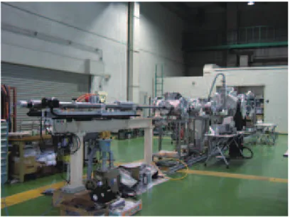
2.1 㣕㣕⩧యຍ㏿⨨
㣕⩧యຍ㏿⨨ࡋ࡚㸪ẁᘧ㍍࢞ࢫ㖠ࢆ⏝ࡋࡓ㸬Fig. 1ᮏᐇ㦂࡛⏝ࡋࡓẁᘧ㍍࢞ࢫ㖠ࢆ♧ ࡍ㸬ẁᘧ㍍࢞ࢫ㖠ࡣ㸪ⅆ⸆ࢆ╔ⅆࡉࡏࡿⅬⅆ㒊㸪ⅆ⸆ࡼࡗ࡚ຍ㏿ࡉࢀࡓࣆࢫࢺ࡛ࣥ㍍࢞ࢫࢆᅽ⦰ࡉ
ࡏࡿ࣏ࣥࣉࢳ࣮ࣗࣈ㸪᭱ࡶ㧗ᅽ࡞ࡿ㧗ᅽ࢝ࢵࣉࣜࣥࢢ㒊㸪㣕⩧యࢆຍ㏿ࡉࡏࡿࣟࣥࢳࢳ࣮ࣗࣈ㸪ࣇࣜ
࣮ࣇࣛࢺ༊㛫࡛࠶ࡿࣇࣛࢺࢳ࣮ࣗࣈ㸪᭱ᚋࢱ࣮ࢤࢵࢺࢆタ⨨ࡍࡿヨᩱᐊࡽᵓᡂࡉࢀ࡚࠸ࡿ㸬
ẁᘧ㍍࢞ࢫ㖠ࡢࣟࣥࢳࢳ࣮ࣗࣈࡣෆᚄ7 mm㸪㛗ࡉ1.5 m㸪ෆ㒊ࡣ1 m࡛1ᅇ㌿ࡍࡿࡽࡏࢇ≧ࡢ ࣛࣇࣝ⁁ࡀࡉࢀ࡚࠸ࡿ㸬ࣟࣥࢳࢳ࣮ࣗࣈࡽⓎᑕࡉࢀࡓࢧ࣎㣕⩧యࡣ㸪ࣇࣛࢺࢳ࣮ࣗࣈෆ࡛ศ
㞳ࡋ㸪ࢧ࣎ࡣࣇࣛࢺࢳ࣮ࣗࣈෆタ⨨ࡉࢀࡓࢧ࣎ࢫࢺࢵࣃ࣮⾪✺㸪㣕⩧యࡣࢧ࣎ࢫࢺࢵࣃ࣮ࡢ୰ᚰ
㒊タࡅࡽࢀࡓ✰ࢆ㏻㐣ࡋ࡚㸪㣕⩧యࡢࡳࢱ࣮ࢤࢵࢺ⾪✺ࡍࡿ㸬
Fig. 1 Two-stage light gas gun at ISAS
2.2 ィィ ⨨
2.2.1 㢧㢧ᚤ㙾ࢩࢫࢸ࣒
࢘ࢵࢺࢿࢫࣉ࣮ࣞࢺୖࡢ⾪✺ࡼࡿࢧࢬศᕸࢆᚓࡿࡓࡵ㸪ගᏛ㢧ᚤ㙾㸦Fig. 2㸧ࢆ⏝ࡋ࢘
Ᏹᐂ⯟✵◊✲㛤Ⓨᶵᵓ◊✲㛤Ⓨ㈨ᩱ䚷㻶㻭㼄㻭㻙㻾㻹㻙㻝㻡㻙㻜㻜㻤 㻞㻠
[Ϩ-2]
ࢵࢺࢿࢫࣉ࣮ࣞࢺࡢᣑ⏬ീࢆྲྀᚓࡋࡓ㸬Table 1⏝ࡋࡓගᏛ㢧ᚤ㙾ࡢᵝࢆ♧ࡍ㸬ࡑࡢࢩࢫࢸ࣒ ࡣ㸪ගᏛ㢧ᚤ㙾㸪ᶓ᩿ཬࡧ⦪㉮⨨㸪AC ࢧ࣮࣮࣎ࣔࢱ㸪ࣃ࣮ࢯࢼࣝࢥࣥࣆ࣮ࣗࢱ㸪సᴗྎࡽᵓᡂࡉ ࢀࡿ㸬㢧ᚤ㙾ࢩࢫࢸ࣒ࡣ㸪ࡲࡎX㍈᪉ྥ୍ᐃ㛫㝸࡛⛣ືࡋ㸦ᶓ⾜㸧⏬ീࢆᙳࡍࡿ㸬ྠࣃ࣮ࢯࢼ ࣝࢥࣥࣆ࣮ࣗࢱ⏬ീࢆಖᏑࡍࡿ㸬ගᏛ㢧ᚤ㙾ࡀ࢘ࢵࢺࢿࢫࣉ࣮ࣞࢺࡢ➃฿㐩ࡍࡿ㸪ᑐഃࡢ➃
⛣ືࡋ㸪 Y㍈᪉ྥ୍ᐃ㛫㝸⛣ືࡋ㸦㉮⾜㸧㸪ୖグືసࢆ⧞ࡾ㏉ࡍ㸬Fig. 3࢘ࢵࢺࢿࢫࣉ࣮ࣞࢺ ࡢᗙᶆࢆ♧ࡍ㸬ࢫ࢟ࣕࢽࣥࢢࢆ⾜࠺㝿㸪ಸ⋡125ಸ࡛ࡣ㸪ᐇ㦂๓ࡢയぢศࡅࡽࢀࡿ᭱ᑠࢧࢬࡣ┤ ᚄ⣙25 Pm࡛࠶ࡗࡓ㸬ಸ⋡125ಸ㸪X㍈Y㍈ࡶ1 mmࡢᙳ㛫㝸࡛ᙳࡋࡓሙྜ㸪1ᯛࡢ㖡ᯈࢆ ᙳࡋ⤊ࢃࡿࡢ⣙6㛫ࡾ㸪⥲ᯛᩘࡣ27,331ᯛ࡛࠶ࡗࡓ㸬
Fig. 2 Microscope system Fig. 3 Coordinate of witness plate
Table 1 Specification of microscope system
Model
number
(Company)
Zoom lens VH-Z35 (KEYENCE) Traverse
equipment SKR46 (THK) Testing bench HA-1510
(SIGMA KOKI)
Magnification 35 ~ 245
Image size [pixel] 640 x 480
Depth of field [mm] 8.3 ~ 0.3
Observation distance [mm] 54
Operating distance [mm] 740 x 940
䛂㻵㻿㻻㻌㻝㻝㻞㻞㻣㻌㻿㼜㼍㼏㼑㻌㼟㼥㼟㼠㼑㼙㼟㻌̿㻌㼀㼑㼟㼠㻌㼜㼞㼛㼏㼑㼐㼡㼞㼑㻌㼠㼛㻌㼑㼢㼍㼘㼡㼍㼠㼑㻌㼟㼜㼍㼏㼑㼏㼞㼍㼒㼠㻌㼙㼍㼠㼑㼞㼕㼍㼘㻌㼑㼖㼑㼏㼠㼍㻌㼡㼜㼛㼚㻌㼔㼥㼜㼑㼞㼢㼑㼘㼛㼏㼕㼠㼥㻌㼕㼙㼜㼍㼏㼠 䠄Ᏹᐂ䝅䝇䝔䝮̿㉸㧗㏿ᗘ⾪✺䛻㉳ᅉ䛩䜛Ᏹᐂᶵᮦᩱ䜲䝆䜵䜽䝍ホ౯䛾䛯䜑䛾ヨ㦂ᡭ㡰䠅䛃
䛻ᇶ䛵䛟ヨ㦂⨨㍑ṇཬ䜃㼑㼖㼑㼏㼠㼍ホ౯ヨ㦂
㻞㻡
[Ϩ-2]
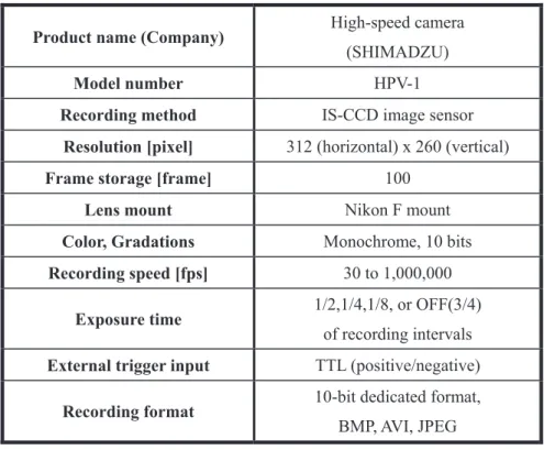
2.2.2 㧗㧗㏿ᗘ࣓࢝ࣛ
EjectaࡢⓎ⏕㐣⛬ࢆᙳࡍࡿࡓࡵ㸪㧗㏿ᗘ࣓࢝ࣛࢆ⏝ࡋࡓ㸬Fig. 4㸪Table 2㧗㏿ᗘ࣓࢝ࣛࡢእ ほཬࡧᵝࢆࡑࢀࡒࢀ♧ࡍ㸬
Fig. 4 High-speed camera
Table 2 Specification of high-speed camera
Product name (Company) High-speed camera
(SHIMADZU)
Model number HPV-1
Recording method IS-CCD image sensor
Resolution [pixel] 312 (horizontal) x 260 (vertical)
Frame storage [frame] 100
Lens mount Nikon F mount
Color, Gradations Monochrome, 10 bits
Recording speed [fps] 30 to 1,000,000
Exposure time 1/2,1/4,1/8, or OFF(3/4)
of recording intervals
External trigger input TTL (positive/negative)
Recording format 10-bit dedicated format,
BMP, AVI, JPEG
3
ヨ
ヨ
㦂ࣃ࣓࣮ࣛࢱ
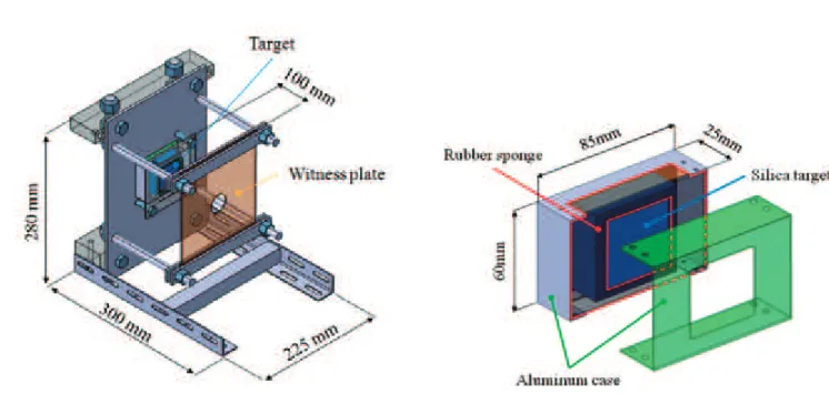
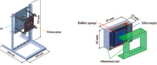
ヨ㦂ࣃ࣓࣮ࣛࢱࢆ௨ୗ♧ࡍ㸬Fig. 5 ࢱ࣮ࢤࢵࢺཬࡧ࢘ࢵࢺࢿࢫࣉ࣮ࣞࢺࡢᵓᡂᅗࢆ♧ࡍ㸬 Ejecta㉁㔞ࡣ㸪ࢱ࣮ࢤࢵࢺࡢᐇ㦂๓ᚋࡢ㉁㔞ᕪࡼࡾ⟬ฟࡍࡿࡀ㸪ࢱ࣮ࢤࢵࢺࡀྜᡂ▼ⱥ࢞ࣛࢫࡢሙྜ㸪
⾪✺ヨ㦂ࡼࡾ࢞ࣛࢫࡢ࢚ࢵࢪࡀࡅ㸪ཝᐦ࡞Ejecta㉁㔞ࡢ⟬ฟࡀᅔ㞴࡛࠶ࡿࡓࡵ㸪ࢱ࣮ࢤࢵࢺࢆFig. 6
Ᏹᐂ⯟✵◊✲㛤Ⓨᶵᵓ◊✲㛤Ⓨ㈨ᩱ䚷㻶㻭㼄㻭㻙㻾㻹㻙㻝㻡㻙㻜㻜㻤 㻞㻢
[Ϩ-2]
ࡢࢱ࣮ࢤࢵࢺ࣍ࣝࢲ࣮ධࢀ࡚ᐇ㦂ࢆ⾜ࡗࡓ㸬࢘ࢵࢺࢿࢫࣉ࣮ࣞࢺࡣ㸪ࢱ࣮ࢤࢵࢺ๓㠃ᨺฟࡉࢀࡓ
Ejectaࢆᤕ⋓ཬࡧ⾪✺ࢲ࣓࣮ࢪࡢホ౯ࢆࡍࡿࡓࡵ⏝ࡍࡿ㸬
Fig. 5 Setup of target and witness plate Fig. 6 Target holder
z 㣕㣕⩧య
つ᱁࡛ࡣ㣕⩧యᮦᩱࡋ࡚A2017A2024ࢆ᥎ዡࡋ࡚࠸ࡿ㸬ᮏᐇ㦂࡛ࡣ㸪௨ୗ♧ࡍࡼ࠺
A2017⌫ࢆ⏝ࡍࡿ㸬
ᮦ
ᮦ㉁㸸࣑ࣝࢽ࣒࢘ྜ㔠㸦Al 2017㸧 ࢧ
ࢧࢬཬࡧᙧ≧㸸┤ᚄ1 mm +/- 0.1 mm⌫ ⾪
⾪✺㏿ᗘ㸦㸦᥎᥎ዡ್㸧㸧㸸5 km/sec +/-100m/sec
ὀ㸸ᮏ⾪✺㏿ᗘࡣ᥎ዡ್࡛࠶ࡾ㸪ᮏᐇ㦂࠾ࡅࡿ⾪✺㏿ᗘࡣ㍑ṇヨ㦂࡛ᐇࡋࡓ㏿ᗘ
‽ࡎࡿࡶࡢࡍࡿ㸬
⾪
⾪✺ゅᗘ㸸0°㸦ࢱ࣮ࢤࢵࢺ⾲㠃ἲ⥺᪉ྥࢆ0°ࡍࡿ㸧
z ࢱࢱ࣮ࢤࢵࢺ
ࢱ࣮ࢤࢵࢺࡣ㸪つ᱁㏻ࡾ㸪⾪✺ࡼࡗ࡚ࢫ࣏࣮ࣝࡀⓎ⏕ࡋ㸪ࡼࡾ࢚ࢪ࢙ࢡࢱࡀᨺฟࡋࡸࡍ࠸
ᮦᩱ࡛࠶ࡿ⁐⼥▼ⱥ࢞ࣛࢫࢆ⏝ࡍࡿ㸬Fig. 7㸪Table 3ࢱ࣮ࢤࢵࢺ⏝ࡋࡓ⁐⼥▼ⱥ࢞ࣛࢫࡢ እほཬࡧᵝࢆࡑࢀࡒࢀ♧ࡍ㸬
䛂㻵㻿㻻㻌㻝㻝㻞㻞㻣㻌㻿㼜㼍㼏㼑㻌㼟㼥㼟㼠㼑㼙㼟㻌̿㻌㼀㼑㼟㼠㻌㼜㼞㼛㼏㼑㼐㼡㼞㼑㻌㼠㼛㻌㼑㼢㼍㼘㼡㼍㼠㼑㻌㼟㼜㼍㼏㼑㼏㼞㼍㼒㼠㻌㼙㼍㼠㼑㼞㼕㼍㼘㻌㼑㼖㼑㼏㼠㼍㻌㼡㼜㼛㼚㻌㼔㼥㼜㼑㼞㼢㼑㼘㼛㼏㼕㼠㼥㻌㼕㼙㼜㼍㼏㼠 䠄Ᏹᐂ䝅䝇䝔䝮̿㉸㧗㏿ᗘ⾪✺䛻㉳ᅉ䛩䜛Ᏹᐂᶵᮦᩱ䜲䝆䜵䜽䝍ホ౯䛾䛯䜑䛾ヨ㦂ᡭ㡰䠅䛃
䛻ᇶ䛵䛟ヨ㦂⨨㍑ṇཬ䜃㼑㼖㼑㼏㼠㼍ホ౯ヨ㦂
㻞㻣
[Ϩ-2]
Fig. 7 Target
ᅛ
ᅛᐃ᪉ἲ㸸⬤ᛶᮦᩱࡢሙྜࡣࢱ࣮ࢤࢵࢺࡢ࢚ࢵࢪࡦࡧࢀཬࡧḞᦆࡀⓎ⏕ࡍࡿྍ⬟ᛶࡀ࠶ࡿ
ࡓࡵ㸪ࢱ࣮ࢤࢵࢺࡢ࿘ࡾࢆࢦ࣒ࢫ࣏ࣥࢪ࡛そ࠸㸪ࡑࢀࡽࢆ࣑ࣝࢣ࣮ࢫࡢෆ㒊ࡵ
ࡿ㸦Fig. 6㸧㸬
Table 3 Specification of target
Target material Fused Silica
Product name (Company) LITHOSIL® (SCHOTT)
Grade QT
Width [mm] 50±1.5
Height [mm] 50±1.5
Thickness [mm] 20±1.0
Mass [g] 110
Density [g/cm3] 2.2
Tensile strength [MPa] 50
Thermal Expansion Coefficient [1/K] 0.51 x 10⁻⁶
Thermal Conductivity [W/(m·K)] 1.31
Electrical Resistivity [::·m] 1.15 x 10¹⁶
Ᏹᐂ⯟✵◊✲㛤Ⓨᶵᵓ◊✲㛤Ⓨ㈨ᩱ䚷㻶㻭㼄㻭㻙㻾㻹㻙㻝㻡㻙㻜㻜㻤 㻞㻤
[Ϩ-2]
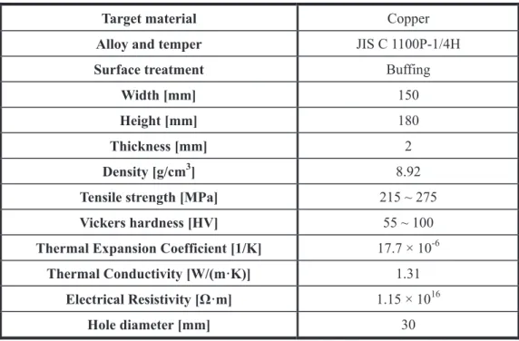
z ࢘࢘ࢵࢺࢿࢫࣉ࣮ࣞࢺ
࢘ࢵࢺࢿࢫࣉ࣮ࣞࢺࡣ㸪ࢱ࣮ࢤࢵࢺ๓㠃ᨺฟࡉࢀࡓ࢚ࢪ࢙ࢡࢱࢆᤕ⋓ཬࡧ⾪✺ࢲ࣓࣮ࢪࡢホ
౯ࢆࡍࡿࡓࡵ⏝ࡍࡿ㸬つ᱁DIS1227ᚑࡗ࡚㸪ᮏᐇ㦂࡛ࡣ㖡ᯈࢆ⏝࠸ࡿ㸬Fig. 8㸪Table 4 ࢘ࢵࢺࢿࢫࣉ࣮ࣞࢺ⏝ࡋࡓ㖡ᯈࡢእほཬࡧᵝࢆࡑࢀࡒࢀ♧ࡍ㸬
Fig. 8 Witness plate
タ
タ⨨㊥㞳㸸ࢱ࣮ࢤࢵࢺ๓㠃ࡽ100 mm
タ
タ⨨ゅᗘ㸸ࢱ࣮ࢤࢵࢺᖹ⾜
ᅛ
ᅛᐃ᪉ἲ㸸Fig. 5♧ࡍࡼ࠺࣑ࣝࢽ࣒࢘ᯈࡼࡾ࢘ࢵࢺࢿࢫࣉ࣮ࣞࢺୖୗࢆᣳࡳᅛᐃࡍࡿ㸬
Table 4 Specification of witness plate
Target material Copper
Alloy and temper JIS C 1100P-1/4H
Surface treatment Buffing
Width [mm] 150
Height [mm] 180
Thickness [mm] 2
Density [g/cm3] 8.92
Tensile strength [MPa] 215 ~ 275
Vickers hardness [HV] 55 ~ 100
Thermal Expansion Coefficient [1/K] 17.7 × 10⁻⁶
Thermal Conductivity [W/(m·K)] 1.31
Electrical ResistLYLW\>ȍāP@ 1.15 × 10¹⁶
Hole diameter [mm] 30
䛂㻵㻿㻻㻌㻝㻝㻞㻞㻣㻌㻿㼜㼍㼏㼑㻌㼟㼥㼟㼠㼑㼙㼟㻌̿㻌㼀㼑㼟㼠㻌㼜㼞㼛㼏㼑㼐㼡㼞㼑㻌㼠㼛㻌㼑㼢㼍㼘㼡㼍㼠㼑㻌㼟㼜㼍㼏㼑㼏㼞㼍㼒㼠㻌㼙㼍㼠㼑㼞㼕㼍㼘㻌㼑㼖㼑㼏㼠㼍㻌㼡㼜㼛㼚㻌㼔㼥㼜㼑㼞㼢㼑㼘㼛㼏㼕㼠㼥㻌㼕㼙㼜㼍㼏㼠 䠄Ᏹᐂ䝅䝇䝔䝮̿㉸㧗㏿ᗘ⾪✺䛻㉳ᅉ䛩䜛Ᏹᐂᶵᮦᩱ䜲䝆䜵䜽䝍ホ౯䛾䛯䜑䛾ヨ㦂ᡭ㡰䠅䛃
䛻ᇶ䛵䛟ヨ㦂⨨㍑ṇཬ䜃㼑㼖㼑㼏㼠㼍ホ౯ヨ㦂
㻞㻥
[Ϩ-2]
z ヨヨ㦂⎔ቃ
つ᱁ᚑ࠸㸪௨ୗࢆタᐃ
ヨ
ヨ㦂 ᗘ㸸ᐊ
ヨ
ヨ㦂ᅽຊ㸸ྍ⬟࡞㝈ࡾ┿✵ᗘࢆ㧗ࡃࡍࡿ㸬㸦⣙12 Pa㸧
4
ヨ
ヨ
㦂ᡭ㡰
ࡇࡇ࡛ࡣ㸪ࢱ࣮ࢤࢵࢺ࣭࢘ࢵࢺࢿࢫࣉ࣮ࣞࢺࡢタ⨨࣭ィ ➼ࡢヨ㦂ᡭ㡰ࡘ࠸࡚グࡍ㸬㣕⩧యຍ
㏿⨨ࡢᐇ㦂ᡭ㡰㛵ࡋ࡚ࡣࡇࡇ࡛ࡣ┬␎ࡍࡿ㸬
4.1 ὀὀព㡯
࢘ࢵࢺࢿࢫࣉ࣮ࣞࢺࢆᢅ࠺㝿ࡣ㸪࢘ࢵࢺࢿࢫࣉ࣮ࣞࢺ⾲㠃ࢆയࡘࡅ࡞࠸ࡼ࠺ᡭ⿄ࢆᚲࡎ╔⏝ࡍ
ࡿ㸬ゎᯒࡢ㝿ᣦ⣠ࡀ╔ࡋ࡚࠸ࡿ⾪✺ࢆ᳨ฟ࡛ࡁ࡞࠸㸬
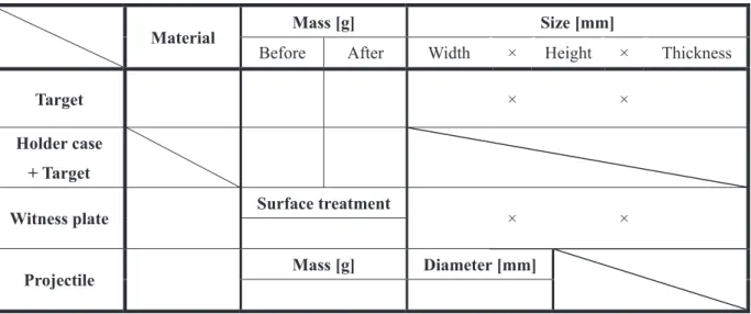
4.2 ヨヨ㦂๓ࡢ‽ഛ
z ヨ㦂๓㣕⩧యཬࡧࢱ࣮ࢤࢵࢺࡢࣃ࣓࣮ࣛࢱ㸦㉁㔞࣭ࢧࢬ㸧ࢆ ᐃࡋ Table 5ࡢࢹ࣮ࢱࢩ࣮ ࢺグධࡍࡿ㸬
z ᐃᚋ㸪ࢱ࣮ࢤࢵࢺࢆ࣍ࣝࢲ࣮ࢣ࣮ࢫධࢀ㸪࣍ࣝࢲ࣮ࢣ࣮ࢫཬࡧࢱ࣮ࢤࢵࢺࡢྜィ㉁㔞ࢆ
ᐃࡍࡿ㸬
z ࢱ࣮ࢤࢵࢺཬࡧ࢘ࢵࢺࢿࢫࣉ࣮ࣞࢺࢆヨᩱᐊෆタ⨨ࡍࡿ㸬࢘ࢵࢺࢿࢫࣉ࣮ࣞࢺࡣ㸪ࢱ࣮
ࢤࢵࢺࡢ๓᪉ 50~100 mm ࡢ⨨タ⨨ࡋ㸪ࢱ࣮ࢤࢵࢺཬࡧ࢘ࢵࢺࢿࢫࣉ࣮ࣞࢺࡢ୰ᚰࢆྜ ࢃࡏࡿ㸬
Table 5 Experimental data sheet
Material Mass [g] Size [mm]
Before After Width × Height × Thickness
Target × ×
Holder case
+ Target
Witness plate Surface treatment × ×
Projectile Mass [g] Diameter [mm]
Ᏹᐂ⯟✵◊✲㛤Ⓨᶵᵓ◊✲㛤Ⓨ㈨ᩱ䚷㻶㻭㼄㻭㻙㻾㻹㻙㻝㻡㻙㻜㻜㻤 㻟㻜
[Ϩ-2]
4.3 ヨヨ㦂ᚋࡢ ᐃ
z ヨ㦂ᚋ㸪ࢱ࣮ࢤࢵࢺཬࡧ࢘ࢵࢺࢿࢫࣉ࣮ࣞࢺࢆྲྀࡾฟࡋ㸪࣍ࣝࢲ࣮ࢣ࣮ࢫཬࡧࢱ࣮ࢤࢵࢺࡢ
ྜィ㉁㔞ࢆ ᐃࡋ㸪Table 5グධࡍࡿ㸬
z ᐇ㦂๓ᚋࡢ㉁㔞ᕪࡽ࢚ࢪ࢙ࢡࢱ㉁㔞Meࢆ⟬ฟࡍࡿ㸬
z ࣍ࣝࢲ࣮ࢣ࣮ࢫࡽࢱ࣮ࢤࢵࢺࢆྲྀࡾฟࡋ㸪⾪✺ཬࡧࢫ࣏࣮ࣝ┤ᚄࢆ ᐃࡋ㸪Table 6グධ ࡍࡿ㸬
Table 6 Experimental results
Impact velocity [km/sec]
Ejected mass [mg]
Diameter [mm] Impact crater
Spall
5
ゎ
ゎ
ᯒᡭ㡰
5.1 ὀὀព㡯
࢘ࢵࢺࢿࢫࣉ࣮ࣞࢺࢆᢅ࠺㝿ࡣ㸪࢘ࢵࢺࢿࢫࣉ࣮ࣞࢺ⾲㠃ࢆയࡘࡅ࡞࠸ࡼ࠺ᡭ⿄ࢆᚲࡎ╔⏝ࡍ
ࡿ㸬ゎᯒࡢ㝿ᣦ⣠ࡀ╔ࡋ࡚࠸ࡿ⾪✺ࢆ᳨ฟ࡛ࡁ࡞࠸㸬
5.2 ゎゎᯒ᪉ἲ
z 㢧ᚤ㙾ࢩࢫࢸ࣒ࡼࡾ࢘ࢵࢺࢿࢫࣉ࣮ࣞࢺ㠃ࡢࢫ࢟ࣕࢽࣥࢢࢆ⾜࠺㸬
z ࢘ࢵࢺࢿࢫࣉ࣮ࣞࢺࡢཎⅬࡣ㸪࢘ࢵࢺࢿࢫࣉ࣮ࣞࢺࡢᕥୖ➃ࢆཎⅬࡋ㸪X㍈ࡣཎⅬࡽ ᕥ᪉ྥࢆṇ㸪Y㍈ࡣཎⅬࡽୗ᪉ྥࢆṇࡋࡓ㸦Fig. 3㸧㸬
z ࢫ࢟ࣕࢽࣥࢢࢆ⾜࠺㝿㸪ಸ⋡ 125 ಸ࡛ࡣ㸪ᐇ㦂๓ࡢയぢศࡅࡽࢀࡿ᭱ᑠࢧࢬࡣ┤ᚄ⣙
25Pm࡛࠶ࡗࡓ㸬┤ᚄ 10Pm௨ୗࡢ⾪✺ࢆ㆑ูࡍࡿࡢ࡛࠶ࢀࡤ㸪200ಸ௨ୖࡢಸ⋡ࡀᚲせ࡛ ࠶ࡿ㸬
z ᚓࡽࢀࡓ㢧ᚤ㙾⏬ീࡽ⾪✺ࢆ᳨ฟࡍࡿ㸬
z ᳨ฟࡉࢀࡓ⾪✺ࡢࢧࢬཬࡧᗙᶆࢆྲྀᚓࡋ㸪௨ୗࡢࢧࢬᇦศ㢮ࡍࡿ㸬
<0.010, 0.01~0.025, 0.025~0.05, 0.05~0.075, 0.075~0.1, 0.1~0.15, 0.15~0.2, 0.2~0.3, 0.3~0.4, 0.4~0.5, 0.5~0.75, 0.75~1.0, >1.0 (mm)
6
ᐇ
ᐇ
㦂⤖ᯝ
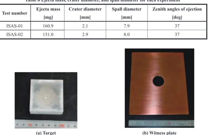
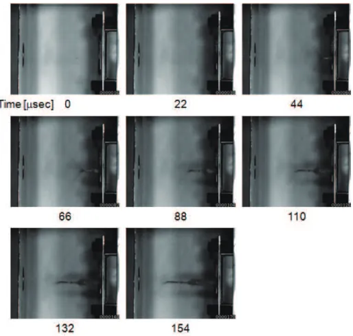
Table 7ཬࡧTable 8ྛᐇ㦂ࡢ⤖ᯝࢆ♧ࡍ㸬ࡲࡓ㸪Fig. 9ISAS-02ࡢᐇ㦂ᚋࡢࢱ࣮ࢤࢵࢺཬࡧ࢘ ࢵࢺࢿࢫࣉ࣮ࣞࢺࢆ♧ࡍ㸬Fig. 10㸪㧗㏿ᗘ࣓࡛࢝ࣛᙳࡋࡓISAS-02ࡢ⏬ീࢆ♧ࡍ㸬ྛᐇ㦂ࡢEjecta
ࡢࢧࢬู⾪✺ศᕸᅗࢆFig. 11㸪⾪✺ࢧࢬูಶᩘศᕸࢆTable 9ཬࡧFig. 12♧ࡍ㸬
䛂㻵㻿㻻㻌㻝㻝㻞㻞㻣㻌㻿㼜㼍㼏㼑㻌㼟㼥㼟㼠㼑㼙㼟㻌̿㻌㼀㼑㼟㼠㻌㼜㼞㼛㼏㼑㼐㼡㼞㼑㻌㼠㼛㻌㼑㼢㼍㼘㼡㼍㼠㼑㻌㼟㼜㼍㼏㼑㼏㼞㼍㼒㼠㻌㼙㼍㼠㼑㼞㼕㼍㼘㻌㼑㼖㼑㼏㼠㼍㻌㼡㼜㼛㼚㻌㼔㼥㼜㼑㼞㼢㼑㼘㼛㼏㼕㼠㼥㻌㼕㼙㼜㼍㼏㼠 䠄Ᏹᐂ䝅䝇䝔䝮̿㉸㧗㏿ᗘ⾪✺䛻㉳ᅉ䛩䜛Ᏹᐂᶵᮦᩱ䜲䝆䜵䜽䝍ホ౯䛾䛯䜑䛾ヨ㦂ᡭ㡰䠅䛃
䛻ᇶ䛵䛟ヨ㦂⨨㍑ṇཬ䜃㼑㼖㼑㼏㼠㼍ホ౯ヨ㦂
㻟㻝
[Ϩ-2]
Table 7 Experimental results
Test number Projectile
material
Alloy and
temper
Surface
treatment
Distance
between T* and
WP** [mm]
Impact
velocity
[km/sec]
Projectile
mass [mg]
ISAS-01
A2017 C1100P-1/4H Buffing 100 4.88 2
ISAS-02 5.18 2
* T: target
** WP: witness plate
Table 8 Ejecta mass, crater diameter, and spall diameter for each experiment
Test number Ejecta mass
[mg]
Crater diameter
[mm]
Spall diameter
[mm]
Zenith angles of ejection
[deg]
ISAS-01 160.9 2.1 7.9 37 ISAS-02 151.0 2.9 8.0 37
(a) Target (b) Witness plate
Ᏹᐂ⯟✵◊✲㛤Ⓨᶵᵓ◊✲㛤Ⓨ㈨ᩱ䚷㻶㻭㼄㻭㻙㻾㻹㻙㻝㻡㻙㻜㻜㻤 㻟㻞
[Ϩ-2]
Fig. 10 High-speed camera image of the test ISAS-02. Recording speed : 500 kfps.
(a) ISAS-01 (b) ISAS-02
䛂㻵㻿㻻㻌㻝㻝㻞㻞㻣㻌㻿㼜㼍㼏㼑㻌㼟㼥㼟㼠㼑㼙㼟㻌̿㻌㼀㼑㼟㼠㻌㼜㼞㼛㼏㼑㼐㼡㼞㼑㻌㼠㼛㻌㼑㼢㼍㼘㼡㼍㼠㼑㻌㼟㼜㼍㼏㼑㼏㼞㼍㼒㼠㻌㼙㼍㼠㼑㼞㼕㼍㼘㻌㼑㼖㼑㼏㼠㼍㻌㼡㼜㼛㼚㻌㼔㼥㼜㼑㼞㼢㼑㼘㼛㼏㼕㼠㼥㻌㼕㼙㼜㼍㼏㼠 䠄Ᏹᐂ䝅䝇䝔䝮̿㉸㧗㏿ᗘ⾪✺䛻㉳ᅉ䛩䜛Ᏹᐂᶵᮦᩱ䜲䝆䜵䜽䝍ホ౯䛾䛯䜑䛾ヨ㦂ᡭ㡰䠅䛃
䛻ᇶ䛵䛟ヨ㦂⨨㍑ṇཬ䜃㼑㼖㼑㼏㼠㼍ホ౯ヨ㦂
㻟㻟
[Ϩ-2]
Table 9 The number of crater
Size
Test No.
0.025 ~ 0.05
[mm]
0.05 ~ 0.075
[mm]
0.075 ~ 0.1
[mm]
0.1 ~ 0.15
[mm]
0.15 ~ 0.2
[mm]
0.2 ~ 0.3
[mm]
ISAS-01 3286 916 343 91 13 1 ISAS-02 2151 843 349 116 18 1
Size
Test No.
0.3 ~ 0.4
[mm]
0.4 ~ 0.5
[mm]
0.5 ~ 0.75
[mm]
0.75 ~ 1.0
[mm]
> 1.0
[mm] Total number
ISAS-01 0 0 0 0 0 4650
ISAS-02 0 0 0 0 0 3478
Fig. 12 The number of crater
7
⤖ㄽ
Ejectaホ౯ヨ㦂ᡭ㡰DIS1227ࡢ➨5❶つ⛬ࡉࢀ࡚࠸ࡿ㍑ṇヨ㦂ࡀ㸪ᕞᕤᴗᏛࡢᐇ㦂タഛ௨እ㸪 ISAS ࡢᐇ㦂タഛ࡛ࡶᐇྍ⬟࡛࠶ࡿࡇࢆ☜ㄆ࡛ࡁࡓ㸬㍑ṇヨ㦂ࡽᚓࡽࢀࡿࢹ࣮ࢱࡢ⌧ᛶࢆ☜ㄆ
ࡋࡓ㸬᭱ᚋࡲࡵࡋ࡚ࠊホ౯ヨ㦂⤖ᯝࢆDIS11227ࡢTable 1ࡢ᭩ᘧ࡛ᩚ⌮ࡋࡓࡶࡢࢆࠊ௨ୗ♧ࡍࠋ
Ᏹᐂ⯟✵◊✲㛤Ⓨᶵᵓ◊✲㛤Ⓨ㈨ᩱ䚷㻶㻭㼄㻭㻙㻾㻹㻙㻝㻡㻙㻜㻜㻤 㻟㻠
[Ϩ-2]
ISAS-01
total amount of
ejecta (mg) : Me 160.9
target mass before impact (mg) 118097.4 target mass after impact (mg) 117936.5
Size distribution of crater
diameter, D
0.025 mm to
0.05 mm
0.05 to 0.1 mm 0.1 to 1 mm >1 mm
front side
number of
craters 3286 1259 105 0
rear side
number of
craters N/A N/A N/A N/A
projectile mass 2.0 mg
ISAS-02
total amount of
ejecta (mg) : Me
151.0 target mass before impact (mg) 118787.0 target mass after impact (mg) 118636.0
Size distribution of crater
diameter, D
0.025 mm to
0.05 mm
0.05 to 0.1 mm 0.1 to 1 mm >1 mm
front side
number of
craters 2151 1192 135 0
rear side
number of
craters N/A N/A N/A N/A
projectile mass 2.0 mg
䛂㻵㻿㻻㻌㻝㻝㻞㻞㻣㻌㻿㼜㼍㼏㼑㻌㼟㼥㼟㼠㼑㼙㼟㻌̿㻌㼀㼑㼟㼠㻌㼜㼞㼛㼏㼑㼐㼡㼞㼑㻌㼠㼛㻌㼑㼢㼍㼘㼡㼍㼠㼑㻌㼟㼜㼍㼏㼑㼏㼞㼍㼒㼠㻌㼙㼍㼠㼑㼞㼕㼍㼘㻌㼑㼖㼑㼏㼠㼍㻌㼡㼜㼛㼚㻌㼔㼥㼜㼑㼞㼢㼑㼘㼛㼏㼕㼠㼥㻌㼕㼙㼜㼍㼏㼠 䠄Ᏹᐂ䝅䝇䝔䝮̿㉸㧗㏿ᗘ⾪✺䛻㉳ᅉ䛩䜛Ᏹᐂᶵᮦᩱ䜲䝆䜵䜽䝍ホ౯䛾䛯䜑䛾ヨ㦂ᡭ㡰䠅䛃
䛻ᇶ䛵䛟ヨ㦂⨨㍑ṇཬ䜃㼑㼖㼑㼏㼠㼍ホ౯ヨ㦂
㻟㻡
➨
➨
Ϩ㸫㸱❶
Ᏹᐂ⯟✵◊✲㛤Ⓨᶵᵓ◊✲㛤Ⓨ㈨ᩱ䚷㻶㻭㼄㻭㻙㻾㻹㻙㻝㻡㻙㻜㻜㻤 㻟㻢
[I-3]
ᴫ
ᴫ せせ
ᮏሗ࿌᭩ࡣISO/TC20/SC14/DIS11227‽ᣐࡋ࡚ᐇࡋࡓᕞᕤᴗᏛ㸭Ᏹᐂ⎔ቃᢏ⾡ࣛ࣎ࣛࢺ࣮ࣜ ࡢẁᘧ㍍࢞ࢫ㖠࠾ࡅࡿ㸪㍑ṇᐇ㦂ࡢᐇᡭ㡰ᐇ⤖ᯝࢆࡲࡵࡓࡶࡢ࡛࠶ࡿ㸬ᐇ㦂ࡣDIS11227
ࡢ➨5❶ᚑࡗ࡚ᐇࡋ㸪➨㸵❶ᚑࡗ࡚ሗ࿌ࢆࡲࡵࡓ㸬 ⾲ADIS11227ࡢ➨5❶࡛せồࡉࢀ࡚ ࠸ࡿᐇ㦂ᐇࣃ࣓࣮ࣛࢱᮏᐇ㦂࡛タᐃࡋࡓࣃ࣓࣮ࣛࢱࡢẚ㍑ࢆ㸪ࡲࡓ⾲BDIS11227ࡢ➨7❶࡛せ ồࡉࢀ࡚࠸ࡿヨ㦂ሗ࿌ࡢෆᐜ㸪ࡑࡢෆᐜᑐᛂࡍࡿᮏ᭩࡛ࡢヱᙜ⟠ᡤ㸦㡯┠␒ྕ㸧ࢆ♧ࡍ㸬࡞࠾, DIS11227ࡢᐇ㦂ࣃ࣓࣮ࣛࢱࡣᚲ㡲㸦shall㸧᮲௳࡛ࡣ࡞࠸ࡀ,ྍ⬟࡞㝈ࡾ㏆࠸ࡇࡀせㄳ㸦”should͇㸧ࡉࢀ ࡚࠾ࡾ,ᮏᐇ㦂ࡢ᮲௳ࡶDIS11227ྍ⬟࡞㝈ࡾྠ୍ࡋࡓ㸬
ᖺᗘཬࡧ ᖺᗘᐇ㦂ࢆᐇࡋࡓ⤖ᯝ㸪ᕞᕤᴗᏛ㸭Ᏹᐂ⎔ቃᢏ⾡ࣛ࣎ࣛࢺ࣮ࣜࡢẁᘧ
㍍࢞ࢫ㖠࡛ISO/TC20/SC14/DIS11227‽ᣐࡋࡓ㍑ṇᐇ㦂ࡢᐇࡀྍ⬟࡛࠶ࡿࡇࢆ☜ㄆࡋࡓ㸬
䛂㻵㻿㻻㻌㻝㻝㻞㻞㻣㻌㻿㼜㼍㼏㼑㻌㼟㼥㼟㼠㼑㼙㼟㻌̿㻌㼀㼑㼟㼠㻌㼜㼞㼛㼏㼑㼐㼡㼞㼑㻌㼠㼛㻌㼑㼢㼍㼘㼡㼍㼠㼑㻌㼟㼜㼍㼏㼑㼏㼞㼍㼒㼠㻌㼙㼍㼠㼑㼞㼕㼍㼘㻌㼑㼖㼑㼏㼠㼍㻌㼡㼜㼛㼚㻌㼔㼥㼜㼑㼞㼢㼑㼘㼛㼏㼕㼠㼥㻌㼕㼙㼜㼍㼏㼠 䠄Ᏹᐂ䝅䝇䝔䝮̿㉸㧗㏿ᗘ⾪✺䛻㉳ᅉ䛩䜛Ᏹᐂᶵᮦᩱ䜲䝆䜵䜽䝍ホ౯䛾䛯䜑䛾ヨ㦂ᡭ㡰䠅䛃
䛻ᇶ䛵䛟ヨ㦂⨨㍑ṇཬ䜃㼑㼖㼑㼏㼠㼍ホ౯ヨ㦂
㻟㻣
[I-3]
⾲
⾲A: DIS11227ࡢ➨5❶࡛せồࡉࢀ࡚࠸ࡿヨ㦂ᐇࣃ࣓࣮ࣛࢱᮏᐇ㦂࡛タᐃࡋࡓࣃ࣓࣮ࣛࢱࡢẚ㍑
DIS11227
This study
Projectile
Material Aluminum alloy
A2017 or A2024 A1050 and A2017
Size and shape 1 mm +/- 0.1 mm
diameter sphere Same
Impact velocity 5 km/s +/- 0.1 km/s 4 km/sec and 5 km/sec
Target
Material Fused silica Synthetic fused silica
Size 50 x 50 x 20 mm
(+/- 1.5 mm) Same
Fixing At the edges onto a
mounting plate
Supported by rubber sponge
Witness
plate
Material Copper
Copper (JIS H3100 C1100P-1/4H,
C1100P-O)
Size 250 x 150 x 2 mm 180 x 150 x 2 mm
Hole diameter 30 mm in the center Same
Distance to the target 50 – 100 mm 50 mm, 100 mm
Position angle to the
target Parallel to the target Same
Fixing
Fixed on the target holding plate by
threaded rods and bolts
Supported by aluminum plates
Surface treatment Not defined
Buffing, Chemical polishing,
Nothing
General
environment
Operating temperature Room temperature Same
Operating pressure < 0.1 Pa ~40 Pa
Ᏹᐂ⯟✵◊✲㛤Ⓨᶵᵓ◊✲㛤Ⓨ㈨ᩱ䚷㻶㻭㼄㻭㻙㻾㻹㻙㻝㻡㻙㻜㻜㻤 㻟㻤
[I-3]
⾲
⾲B: ᮏ᭩㸦ḟ࣮࣌ࢪࡼࡾࡢሗ࿌㸧DIS11227ࡢ➨7❶࡛せồࡉࢀࡿሗ࿌᭩ෆᐜࡢẚ㍑
DIS11227
➨
➨
㸵❶࡛せồࡉࢀࡿሗ࿌᭩ෆᐜ
ᮏ
ᮏ
᭩ࡢヱᙜ⟠ᡤ
1. an abstract summarizing the test procedure and findings; 1. ᐇ㦂ᡭ㡰⤖ᯝࢆせ⣙ࡋ࡚࠸ࡿᴫせ
࠙
࠙ᴫせࠚ
1 ┠┠ⓗ
2. an introduction which provides the background information to the test (i.e. reason for testing, use and applicability of results); 2. ヨ㦂࠾ࡅࡿ⫼ᬒࢆ࠼ࡿᗎㄽ㸦࠼ࡤ㸪ヨ㦂ࡢࡓࡵࡢືᶵ㸪 ⤖ᯝࡢ㐺⏝ᛶࡸ⏝㸧
1 ┠┠ⓗ
3. the objective of the test activity;
3. ヨ㦂άືࡢ┠ⓗ 1
┠
┠ⓗ
4. information on the tested material;
4. ヨ㦂∦ࡘ࠸࡚ࡢሗ 3
ヨ
ヨ㦂ࣃ࣓࣮ࣛࢱ
5. a description of the test procedure and test conditions; 5. ᐇ㦂ᡭ㡰ᐇ㦂᮲௳ࡢゎㄝ
2 ᐇᐇ㦂⨨
2.1 㣕㣕⩧యຍ㏿⨨
2.2 ィィ ⨨
2.2.1 㟁㟁Ꮚኳ⛗
2.2.2 㢧㢧ᚤ㙾ࢩࢫࢸ࣒
2.2.3 㧗㧗㏿ᗘ࣓࢝ࣛ
3 ヨヨ㦂ࣃ࣓࣮ࣛࢱ
4 ヨヨ㦂ᡭ㡰
4.1 ὀὀព㡯
4.2 ヨヨ㦂๓ࡢࡢ‽‽ഛ
4.3 ヨヨ㦂ᚋᚋࡢ ᐃ
5 ゎゎᯒᡭ㡰
5.1 ὀὀព㡯
5.2 ゎゎᯒ᪉ἲ
6. the calibration report ;
6. ㍑ṇヨ㦂ሗ࿌ 6 ᐇᐇ㦂⤖ᯝ
7. presentation of results;
7. ⤖ᯝࡢᥦ♧ 6
ᐇ
ᐇ㦂⤖ᯝ
8. discussion of results;
8. ⤖ᯝࡢ⪃ᐹ 6
ᐇ
ᐇ㦂⤖ᯝ
9. conclusions and recommendations;
9. ⤖ㄽᥦゝ 7⤖⤖ㄽ
10. numerical data in a format agreed by the customer;
10. 㢳ᐈࡼࡗ࡚ᢎㅙࡉࢀࡓᙧᘧࡢᩘ್ࢹ࣮ࢱ N/A
11. Customer’s authorization about the tests.
11. ヨ㦂ࡘ࠸࡚ࡢ㢳ᐈࡢᢎㄆ N/A
䛂㻵㻿㻻㻌㻝㻝㻞㻞㻣㻌㻿㼜㼍㼏㼑㻌㼟㼥㼟㼠㼑㼙㼟㻌̿㻌㼀㼑㼟㼠㻌㼜㼞㼛㼏㼑㼐㼡㼞㼑㻌㼠㼛㻌㼑㼢㼍㼘㼡㼍㼠㼑㻌㼟㼜㼍㼏㼑㼏㼞㼍㼒㼠㻌㼙㼍㼠㼑㼞㼕㼍㼘㻌㼑㼖㼑㼏㼠㼍㻌㼡㼜㼛㼚㻌㼔㼥㼜㼑㼞㼢㼑㼘㼛㼏㼕㼠㼥㻌㼕㼙㼜㼍㼏㼠 䠄Ᏹᐂ䝅䝇䝔䝮̿㉸㧗㏿ᗘ⾪✺䛻㉳ᅉ䛩䜛Ᏹᐂᶵᮦᩱ䜲䝆䜵䜽䝍ホ౯䛾䛯䜑䛾ヨ㦂ᡭ㡰䠅䛃
䛻ᇶ䛵䛟ヨ㦂⨨㍑ṇཬ䜃㼑㼖㼑㼏㼠㼍ホ౯ヨ㦂
㻟㻥
[Ϩ-3]
2009ᖺᗘཬࡧ2011ᖺᗘ㸪ᕞᕤᴗᏛ㸭Ᏹᐂ⎔ቃᢏ⾡ࣛ࣎ࣛࢺ࣮ࣜタ⨨ࡉࢀ࡚࠸ࡿヨ㦂⨨࡚㸪
ISO/TC20/SC14/DIS11227‽ᣐࡋࡓ㍑ṇᐇ㦂ࢆ⾜ࡗࡓ㸬௨ୗ㸪ᐇෆᐜࢆグࡍ㸬
1
┠
┠
ⓗ
㉸㧗㏿⾪✺࡛ᑕฟࡉࢀࡓ㣕⩧యࡢ⾪✺ࡼࡗ࡚Ⓨ⏕ࡍࡿ Ejecta ࢆᅇࡋ㸪ゎᯒࢆ⾜࠺ࡲ࡛ࡢ୍㐃ࡢ ᐇ㦂ᡭ㡰ཬࡧᐇ㦂せ௳ࡘ࠸࡚グ㍕ࡋ࡚࠸ࡿ㸬㉸㧗㏿⾪✺ヨ㦂ࡢᐇ㦂ᡭ㡰ࡣ㸪ྛᅜヨ㦂タࡈ␗࡞
ࡗ࡚࠸ࡿࡢࡀ୍⯡ⓗ࡛࠶ࡾ㸪┦ࡢヨ㦂⤖ᯝࢆඹ㏻ࡢどⅬࡽホ౯ࡋ࠶࠺ࡢࡣᅔ㞴࡞ሙྜࡀከ࠸㸬ࡑࡇ
࡛㸪ᮏ᭩ࡢ┠ⓗࡋ࡚ࡣ㸪ᐇ㦂ᡭ㡰ཬࡧᐇ㦂せ௳ࢆグ㍕ࡍࡿࡇ࡛㸪ヨ㦂タࡈྲྀᚓࡉࢀࡓヨ㦂⤖
ᯝࢆホ౯ࡋࡸࡍࡃࡍࡿࡇ࡛࠶ࡿ㸬≉㸪Ejectaホ౯ヨ㦂ᡭ㡰DIS1227ࡢ➨5❶つ⛬ࡉࢀ࡚࠸ࡿ㸪㍑ ṇヨ㦂ࢆᐇࡋ㸪ᐇྍ⬟࡛࠶ࡿࡇࢆ☜ㄆࡍࡿ㸬ࡲࡓ㸪ྠᩥ᭩ࡢᨵၿࡍࡁ㡯ࢆᢳฟࡍࡿࡇࢆヨ
㦂┠ⓗࡍࡿ㸬
2
ᐇ
ᐇ
㦂⨨
ᕞᕤᴗᏛ࡛⾜ࡗࡓEjectaヨ㦂࠾࠸࡚⏝ࡋࡓᐇ㦂⨨ࢆ௨ୗ♧ࡍ㸬
2.1 㣕㣕⩧యຍ㏿⨨
㣕⩧యຍ㏿⨨ࡋ࡚㸪ẁᘧ㍍࢞ࢫ㖠ࢆ⏝ࡋࡓ㸬Fig. 1ᮏᐇ㦂࡛⏝ࡋࡓẁᘧ㍍࢞ࢫ㖠ࢆ♧ ࡍ㸬ẁᘧ㍍࢞ࢫ㖠ࡣ㸪ⅆ⸆ࢆ╔ⅆࡉࡏࡿⅬⅆ㒊㸪ⅆ⸆ࡼࡗ࡚ຍ㏿ࡉࢀࡓࣆࢫࢺ࡛ࣥ㍍࢞ࢫࢆᅽ⦰ࡉ
ࡏࡿ࣏ࣥࣉࢳ࣮ࣗࣈ㸪᭱ࡶ㧗ᅽ࡞ࡿ㧗ᅽ࢝ࢵࣉࣜࣥࢢ㒊㸪㣕⩧యࢆຍ㏿ࡉࡏࡿࣟࣥࢳࢳ࣮ࣗࣈ㸪ᚋ᪉
ࡽࡢ࢞ࢫࢆᣑᩓࡉࡏࡿࣈࣛࢫࢺࢱࣥࢡ㸪ࢧ࣎ࢆ✵Ẽᢠࡼࡾศ㞳ࡉࡏࡿࢧ࣎ศ㞳༊㛫㸪᭱ᚋࢱ࣮
ࢤࢵࢺࢆタ⨨ࡍࡿヨᩱᐊࡽᵓᡂࡉࢀ࡚࠸ࡿ㸬㣕⩧యࡢ㏿ᗘィ ࡣ㸪࣮ࣞࢨ࣭࢝ࢵࢺἲࢆ⏝ࡋࡓ㸬
ẁᘧ㍍࢞ࢫ㖠ࡢࣟࣥࢳࢳ࣮ࣗࣈࡣෆᚄ5mm㛗ࡉ0.935m㸦2009ᖺᗘ㸧㸪ෆᚄ6mm㛗ࡉ1.2m㸦2011
ᖺᗘ㸧࡛࠶ࡿ㸬ࣟࣥࢳࢳ࣮ࣗࣈࡼࡾⓎᑕࡉࢀࡓࢧ࣎㣕⩧యࡣ㸪✵Ẽᢠࡼࡾࢧ࣎ศ㞳༊㛫࡛ศ㞳ࡋ㸪
ࢧ࣎ศ㞳༊㛫ෆタ⨨ࡉࢀࡓࢧ࣎ศ㞳ᯈ⾪✺㸪㣕⩧యࡣࢧ࣎ศ㞳ᯈࡢ୰ᚰタࡅࡽࢀࡓ✰ࢆ㏻㐣ࡋ࡚㸪
㣕⩧యࡢࡳࡀࢱ࣮ࢤࢵࢺ⾪✺ࡍࡿ㸬
Ᏹᐂ⯟✵◊✲㛤Ⓨᶵᵓ◊✲㛤Ⓨ㈨ᩱ䚷㻶㻭㼄㻭㻙㻾㻹㻙㻝㻡㻙㻜㻜㻤 㻠㻜
[Ϩ-3]
(b) External view
Fig. 1 Two-stage light gas gun at KIT (Kyushu Institute of Technology)
2.2 ィィ ⨨
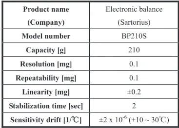
2.2.1 㟁㟁Ꮚኳ⛗
ࢱ࣮ࢤࢵࢺ㸪㣕⩧యࡢ㉁㔞ࢆィ ࡍࡿࡓࡵ㟁Ꮚኳ⛗ࢆ⏝ࡋࡓ㸬Fig. 2㸪Table 1㟁Ꮚኳ⛗ࡢእ ほཬࡧᵝࢆࡑࢀࡒࢀ♧ࡍ㸬ᨺฟࡉࢀࡿEjecta㉁㔞ࡀᩘ༑mg⛬ᗘ࡛࠶ࡿࡓࡵ㸪ኳ⛗ࡢㄞྲྀ㝈ᗘ 0.1g
௨ୗࡢࡶࡢࢆ⏝ࡋࡓ㸬
Fig. 2 Electronic balance
Table 1 Specification of electronic balance
Product name
(Company)
Electronic balance (Sartorius)
Model number BP210S
Capacity [g] 210
Resolution [mg] 0.1
Repeatability [mg] 0.1
Linearity [mg] ±0.2
Stabilization time [sec] 2
Sensitivity drift [1/ΥΥ] ±2 x 10⁻⁶ (+10 ~ 30Υ)
2.2.2 㢧㢧ᚤ㙾ࢩࢫࢸ࣒
࢘ࢵࢺࢿࢫࣉ࣮ࣞࢺୖࡢ⾪✺ࡼࡿࢧࢬศᕸࢆᚓࡿࡓࡵ㸪ගᏛ㢧ᚤ㙾㸦Fig. 3㸧ࢆ⏝ࡋ࢘ ࢵࢺࢿࢫࣉ࣮ࣞࢺࡢᣑ⏬ീࢆྲྀᚓࡋࡓ㸬Table 2⏝ࡋࡓගᏛ㢧ᚤ㙾ࡢᵝࢆ♧ࡍ㸬ࡑࡢࢩࢫࢸ࣒ ࡣ㸪ගᏛ㢧ᚤ㙾㸪ᶓ᩿ཬࡧ⦪㉮⨨㸪AC ࢧ࣮࣮࣎ࣔࢱ㸪ࣃ࣮ࢯࢼࣝࢥࣥࣆ࣮ࣗࢱ㸪సᴗྎࡽᵓᡂࡉ
![Table 9 The number of crater Size Test No. 0.025 ~ 0.05 [mm] 0.05 ~ 0.075 [mm] 0.075 ~ 0.1 [mm] 0.1 ~ 0.15 [mm] 0.15 ~ 0.2 [mm] 0.2 ~ 0.3 [mm] ISAS-01 3286 916 343 91 13 1 ISAS-02 2151 843 349 116 18 1 Size Test No](https://thumb-ap.123doks.com/thumbv2/123deta/8209229.370799/32.892.66.824.188.792/table-number-crater-size-test-isas-isas-size.webp)