1
Electrochemical Na-insertion/extraction properties of
SnO thick-film electrodes prepared by gas-deposition
Masahiro Shimizua,b, Hiroyuki Usuia,b, and Hiroki Sakaguchia,b,*
aDepartment of Chemistry and Biotechnology, Graduate School of Engineering, Tottori University 4-101 Minami, Koyama-cho, Tottori 680-8552, Japan
bCenter for Research on Green Sustainable Chemistry, Tottori University 4-101 Minami, Koyama-cho, Tottori 680-8552, Japan
*Corresponding author. Tel./Fax: +81-857-31-5265; e-mail: sakaguch@chem.tottori-u.ac.jp
Keywords: SnO anode; Na-ion battery; Thick-film electrode; Electrolyte additive; Gas-deposition
method
Abstract
SnO thick-film electrodes for Na-ion battery anodes were prepared for the first time by a gas-deposition method, and we investigated the influence of fluoroethylene carbonate as an electrolyte additive on their anode performances. The SnO electrode showed high reversible capacities of 580 mA h g-1 and 260 mA h g-1
at the first cycle and at the 20thcycle, respectively, in an additive-free electrolyte. The cycle performance obtained was much higher than that of an Sn electrode. These results indicate that Na2O formed in the first Na-insertion process played a role as a matrix to alleviate a stress generated by drastic volumetric changes during alloying/dealloying reactions of Sn with Na. When we used fluorothylene carbonate as an additive, the SnO electrode achieved 250 mA h g-1 at the 50th cycle with a good capacity retention. The excellent cycle performance originates from a facile Na-ion transfer through a surface layer formed between the electrode and the electrolyte because the surface layer derived from additive prevents from making itself thicker by suppressing decomposition of the electrolyte.
2
1. Introduction
Na-ion battery has received interest in large-scale battery system due to its low cost and widespread availability of sodium resources [1]. It is, however, difficult to develop the suitable anode material for reversible Na-insertion/extraction because an Na ion has larger ionic radius than an Li ion. Although carbon-based materials enable to absorb Na ions which are comparable to a capacity of ca. 250-300 mA h g-1 andgood capacity retention [2-4], high capacity Na-storage anodes are required to further increase the energy density of Na-ion battery. Sn is one of promising candidates of anode materials due to its high theoretical capacity of 847 mA h g-1 compared with carbonaceous anodes [5-8]. This large capacity originates from an alloying reaction of Na–Sn in the composition range from Sn to Na15Sn4. The volume of Sn is, however, significantly changed during charge–discharge cycle, which leads to disintegration of Sn anode and poor cycle performance. Komaba et al. have demonstrated an improved cyclability of Sn electrode by employing both polyacrylate binder and electrolyte additive [9]. On the other hand, SnO anodes for Li-ion battery show superior cycle performance. It has been reported that Li2O formed in the first cycle plays a role as buffer to alleviate a stress induced by volumetric changes during Li-insertion/extraction [10-12], and that the aggregation of Sn particle is suppressed by Li2O [13]. As for Na-ion battery anodes, no study has been, however, reported for SnO to the authors’ knowledge. We are here suggesting for the first time that SnO has a potential as anode for Na-ion battery with a good electrode performance.
Gas-deposition (GD) method is very favorable for evaluating electrode performance of active material, which has been recently demonstrated by the authors [14-16]. This method does not require any binder and conductive additive to prepare thick-film electrodes. The feature is a unique advantage to clarify an original anode performance of pure SnO anode.
In this study, we prepared SnO thick-film electrodes by the GD method, and investigated their electrochemical Na-insertion/extraction properties. In addition, we tried to improve their cycle performances by applying fluoroethylene carbonate to electrolyte additive.
3
2. Experimental
SnO powder (Wako Pure Chemical Industries, Ltd. 99.9%) was used as an active material. For comparison, we used Sn powder (Kojundo Chemical Lab. Co., Ltd. 325 mesh, 99.99%) also. Thick-film electrodes were prepared by a gas-deposition method [14-16]. For gas-deposition, a current collector of Cu foil substrate with 20 µm in thickness was set at a distance of 10 mm from a nozzle in a vacuum chamber with a guide tube. The nozzle with 0.8 mm in diameter was connected at the end of guide tube. An argon carrier gas with a purity of 99.99% was set under a differential pressure of 7.0×10⁵ Pa. After the chamber was evacuated to a base pressure of several ten Pa, an aerosol consisting of the carrier gas and the active material powder was generated in the guide tube, and instantly gushed from the nozzle to the Cu substrate. The weight of the deposited active materials on the substrate and the deposition area were 80–100 µg and 0.80 cm2, respectively. We assembled 2032-type coin cells consisted of the thick-film electrodes as working electrode, Na foil as counter electrode, electrolyte, and propylene-based separator. The electrolytes used in this study were 1 M NaClO4-disssolved in
propylene carbonate (PC; C4H6O3, Kishida Chemical Co., Ltd.) without and with addition of 20 vol.%
fluoroethylene carbonate (FEC; C3H3FO3, Kanto Denka Kogyo Co., Ltd.). The gas-deposition and the cell assembly were performed throughout in a purge-type glove box (Miwa MFG, DBO-2.5LNKP-TS) filled with an Ar atmosphere in which O2 and H2O were completely removed. In the glove box, a dew point and oxygen content were maintained below –100°C and below 1 ppm, respectively. Constant current charge–discharge tests were carried out using an electrochemical measurement system (HJ-1001 SM8A, Hokuto Denko Co., Ltd.) in the potential range between 0.005 and 2.000 V vs. Na/Na+ at 303 K under the constant current density of 50 mA g-1 (0.07 C). The surface morphologies of the thick-film electrodes were observed by using a field-emission scanning electron microscope (FE-SEM, JSM-6701F JEOL Co., Ltd.). A crystal structure of active materials was investigated by using X-ray diffractometer (Ultima IV Rigaku Co., Ltd.) with CuKα radiation. Raman spectra of the powder were
4
measured by using a Raman microscopy system (NanofinderFLEX, Tokyo Instruments, Inc.) at room temperature. As a reference sample, SnO2 (Wako Pure Chemical Industries, Ltd. 99.9%) was also measured.
3. Results and discussion
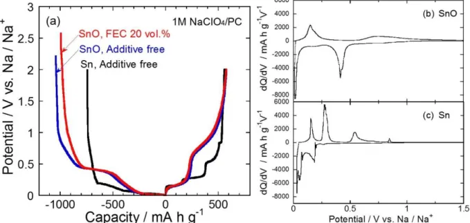
Fig. 1(a) shows the first charge–discharge (Na insertion–extraction) curves for SnO and Sn thick-film electrodes. In the Sn electrode, the initial charge and discharge capacities were 740 and 560 mA h g-1, respectively, with the first coulombic efficiency of 76%. The irreversible capacity is attributed to reductive decomposition of electrolyte. Four plateaus were observed in a potential range between 0.15 and 0.85 V vs. Na/Na+ on the discharge curve. These plateaus indicate that Sn and Na formed binary alloy phases, NaSn3, α-NaSn, Na9Sn4, and Na15Sn4, as reported by Obrovac et al. [17]. On the other hand, SnO electrode delivered the initial discharge capacity of 580 mA h g-1, which is approximately two times larger than that obtained from carbon-based anode [2,3]. The initial charge capacity and coulombic efficiency were 1040 mA h g-1 and 56%, respectively. It is considered that the low coulombic efficiency was caused by an irreversible reaction of SnO with Na in the first charge process. Fig. 1(b) and 1(c) give differential capacity (dQ/dV) curvesat the first cycle for the SnO and Sn electrodes to discuss the charge–discharge reaction. In the cathodic profile, the SnO electrode showed two sharp peaks at 0.41 V and 0.015 V and a broad peak at 0.18 V vs. Na/Na+. The peak at 0.41 V is attributed to a reductive reaction of SnO to form metallic Sn and Na2O. We did not confirm the peak at 0.41 V in the subsequent charge–discharge cycles, indicating that the reductive reaction is irreversible. The broad peak at around 0.18 V and the sharp peak at 0.015 V vs. Na/Na+ are assigned to alloying reactions of Sn with Na such as a crystalline Na15Sn4 phase, which corresponds to the dQ/dV profiles of not only our Sn electrode but also those of other Sn-based electrode [5]. In the anodic profile, we observed a sharp peak at 0.14 V and a very broad peak at a region from 1.5 to 0.6 V vs. Na/Na+. These peaks are related to Na-extraction from each Na–Sn phase [5,6,17]. Consequently, SnO
5
appears to react with Na as shown in the following equations:
SnO + 2Na+ + 2e- → Sn + Na2O (1) 4Sn + 15Na+ + 15e-
⇄ Na15Sn4 (2)
From a calculation based on the reaction mechanism mentioned above, the SnO provides the theoretical capacity of 746 mA h g-1. In this study, the reversible capacity was 580 mA h g-1
, which was smaller than the theoretical capacity. The relatively small capacity was caused by a decrease in utilization of active material due to poor electrical conductivity of oxide. Raman spectrum of SnO powder used in this study showed SnO2 being, though we could not recognize SnO2 in XRD pattern of the SnO powder, (see Fig. S1 and S2 in supporting information). The result indicates that relative content of Sn in the active material is smaller than that in a pure SnO, which also restricts reversible capacity obtained from Na–Sn alloying reaction.
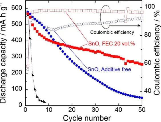
Fig. 2 represents cycling performances and coulombic efficiencies of the SnO and Sn electrodes in 1 M NaClO4/PC without and with 20 vol.% FEC. Although the Sn electrode showed a comparatively high discharge capacity of 560 mA h g-1 at the first cycle, the capacity was quickly decreased to 30 mA h g-1 by the sixth cycle, resulting in a very poor cycle performance. The reason for the capacity decay is probably the disintegration of Sn electrode caused by the stress. The volume of Sn is significantly changed during Na-insertion/extraction process, and the expansion ratio of the specific volume from β-Sn to Na15Sn4 reaches approximately 530%. The mechanical stress induced by repeating charge–discharge cycle leads to the deterioration of Sn electrode [5,6]. We confirmed that the Sn electrode showed low coulombic efficiencies of less than 90% for initial sixth cycles (not shown here). It is considered that the low reversibility also results from the disintegration of the Sn electrode. In contrast, the SnO electrode in the additive-free electrolyte maintained the discharge capacity of 260 mA h g-1 at the 20th cycle, which was superior cycle performance to that of the Sn electrode. This better cyclability is possibly attributed to structural feature. We are here suggesting that Na2O formed in the first cycle plays a role as a matrix to release the stress, leading to the better cyclability of SnO
6
electrode as similar to Li–SnO system [10-12]. The capacity decay was, nevertheless, observed in the subsequent cycles, and the discharge capacity decreased to only about 50 mA h g-1 by the 50th cycle. This phenomenon was presumably arisen from two reasons. One is the disintegration of SnO electrode. The other reason is a deterioration of transport property of Na-ion in a surface layer formed between the electrode and the electrolyte. In the first cycle, electrolytes based on PC solvent are decomposed to form the surface layer consisted of organic and/or inorganic compounds on the anode [18]. In the case of Sn-based material as an anode, the drastic volume expansion and contraction occur by alloying and dealloying reactions of Sn with Na, which causes the partial damages of the surface layer to expose new surfaces of active material layer. The surface layers are reconstructed by decomposition of the electrolyte at the next charge process [19]. We considered that the continuous formation of surface layer makes itself thicker and prevents the Na-ion transfer through it, leading to the decrease in utilization of active material [20,21]. It is widely known that FEC is an effective electrolyte additive for improving cycle performance by passivating surface of Sn-based anodes. [9,22]. In order to improve the cycle performance of the SnO electrode, we used FEC-added electrolyte to modify the surface of SnO electrode. As shown in Fig. 1(a), the SnO electrode in the electrolyte containing FEC exhibited the initial capacity of 570 mA h g-1 and similar potential profile to that in the electrolyte without FEC. The first coulombic efficiency of 58% was observed. There was no significant difference in the first coulombic efficiencies between each SnO electrode in both the electrolytes. Although the coulombic efficiency of SnO electrode in the additive-free electrolyte was temporarily increased to 92% at the third cycle, the coulombic efficiency was decreased to 84% at the tenth cycle and was remained below 90% until 40th cycle. We consider that these behaviors indicate not only the disintegration of the SnO electrode but also the continuous decomposition of electrolyte. In contrast, the SnO electrode in the electrolyte with FEC constantly exhibited higher coulombic efficiencies than those obtained in the additive-free electrolyte, and the coulombic efficiency was improved to 98% after the sixth cycle. This enhanced reversibility means that the further decomposition of electrolyte was
7
suppressed by introducing FEC additive. It was noteworthy that the SnO electrode achieved a high capacity of 250 mA h g-1 even at the 50th cycle. As a result, the capacity retention was remarkably improved to 44%, which was five times higher than that in the electrolyte without FEC.
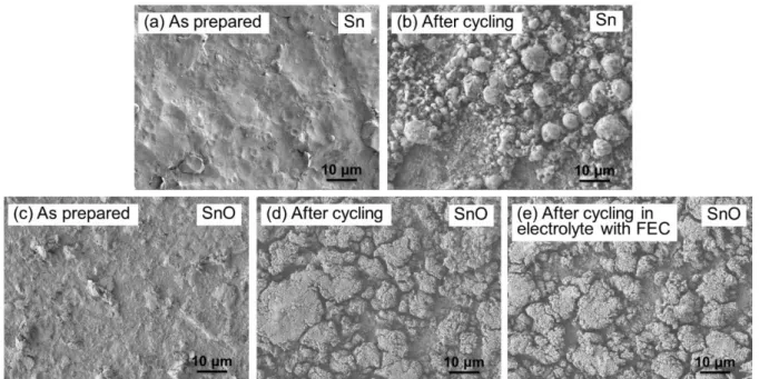
Fig. 3 displays FE-SEM images of the SnO and Sn electrodes as prepared and after charge– discharge cycling, respectively, in the electrolytes without and with 20 vol.% FEC. The Sn and SnO electrodes before cycling showed smooth surface, respectively, as shown in Fig. 3(a), (c). In Fig. 3(b), we can clearly observe the disintegration of the Sn electrode related to the rapid capacity fading. In both the SnO electrodes after cycling, we confirmed changes in surface morphology such as the formation of cracks. It is notable point that degrees of disintegration for both the SnO electrodes after cycling in the electrolytes without and with FEC additive were mostly similar (see Fig. 3(d), (e)). These results indicate that the capacity decay originates from not only disintegration of SnO electrodes but also deteriorated Na-ion transfer between the electrode and the electrolyte [23]. It was demonstrated that SnO electrode exhibited the initial high discharge capacity and the good cycle performance because FEC additive effectively enhanced the utilization of active material by suppressing deterioration of the Na-ion transfer.
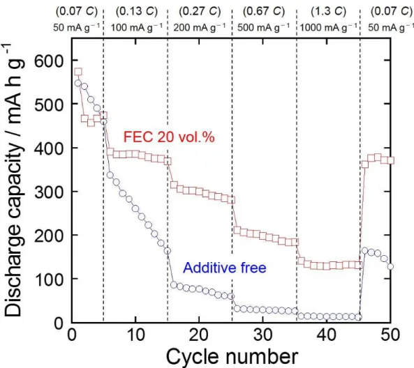
The improved Na-ion transfer is expected to upgrade an anode performance of SnO electrode at high-rate charge–discharge condition. Fig. 4 displays the rate performance of SnO electrodes in the electrolytes of 1 M NaClO4/PC without and with 20 vol.% FEC. The rate capability was evaluated at various current densities from 50 mA g-1 to 1000 mA g-1
. These current densities correspond to a current rate of 0.07 C to 1.3 C because we defined 746 mA g-1 as 1.0 C from the reaction of SnO with Na. The SnO electrode in the additive-free electrolyte showed a rapid capacity fading with increasing current density, suggesting the deterioration of transport property of Na-ion in the surface layer formed between the electrode and the electrolyte. On the other hand, the SnO electrode in FEC-added electrolyte achieved a comparatively high capacity of ca. 200 mA h g-1 even at a high current density of 500 mA g-1 (0.67 C). Moreover, when the current density returns to 50 mA g-1
8
discharge capacity can be recovered, which indicates that FEC additive keeps good Na-ion transfer for long-term charge–discharge cycling.
4. Conclusion
The SnO thick-film electrodes were prepared by a GD method, and their anode performances for Na-ion battery were investigated. When we used FEC additive, the SnO electrode exhibited the initial high discharge capacity of 570 mA h g-1 and achieved 250 mA h g-1
at the 50th cycle. In addition to these, the SnO electrode showed a high-rate performance with the capacity of ca. 200 mA h g-1 at the high current density of 500 mA g-1. From the results of FE-SEM observation, it was revealed that these excellent electrode performances result from structural integrity of SnO and improved the Na-ion transfer by introducing FEC additive.
Acknowledgments
This work has been supported in part by the Adaptable and Seamless Technology transfer Program through target-driven R&D funding from the Japan Science and Technology Agency (JST), and by a Grantin-Aid for Scientific Research from the Ministry of Education, Culture, Sports, Science and Technology (MEXT) of Japan. The authors thank Dr. H. Furutani (KANEKA Co., Japan) for supplying chemicals.
9
References
[1] S. Komaba, W. Murata, T. Ishikawa, N. Yabuuchi, T. Ozeki, T. Nakayama, A. Ogata, K. Gotoh, K. Fujiwara, Adv. Funct. Mater. 21 (2011) 3859.
[2] Y. Cao, L. Xiao, M. L. Sushko, W. Wang, B. Schwenzer, J. Xiao, Z. Nie, L. V. Saraf, Z. Yang, J. Liu, Nano Lett. 12 (2012) 3783.
[3] A. Ponrouch, A.R. Goñi, M. R. Palacín, Electrochem. Commun. 27 (2013) 85. [4] M. Egashira, T. Tanaka, N. Yoshimoto, M. Morita, Electrochemistry 80 (2012) 755.
[5] M. K. Datta, R. Epur, P. Saha, K. Kadakia, S. K. Park, P. N. Kumta, J. Power Sources 225 (2013) 316.
[6] Y. Xu, Y. Zhu, Y. Liu , C. Wang, Adv. Energy Mater. 3 (2013) 128. [7] V. L. Chevrier, G. Ceder, J. Electrochem. Soc. 158 (2011) A1011.
[8] T. Yamamoto, T. Nohira, R. Hagiwara, A. Fukunaga, S. Sakai, K. Nitta, S. Inazawa, J. Power
Sources 217 (2012) 479.
[9] S. Komaba, Y. Matsuura, T. Ishikawa, N. Yabuuchi, W. Murata, S. Kuze, Electrochem. Commun.
21 (2012) 65.
[10] Y. Idota, T. Kubota, A. Matsufuji, Y. Maekawa, T. Miyasaka, Science 276 (1997) 1395.
[11] D. Aurbach, A. Nimberger, B. Markovsky, E. Levi, E. Sominski, A. Gedanken, Chem. Mater. 14 (2002) 4155.
[12] S.-C. Chao, Y.-C. Yen, Y.-F. Song, H.-S. Sheu, H.-C. Wu, N.-L. Wu, J. Electrochem. Soc. 158 (2011) A1335.
[13] I. A. Courtney, W. R. McKinnon, J. R. Dahn, J. Electrochem. Soc. 146 (1999) 59.
[14] H. Sakaguchi, T. Toda, Y. Nagao, T. Esaka, Electrochem. Solid-State Lett. 10 (2007) J146. [15] H. Usui, Y. Kiri, H. Sakaguchi, Thin Solid Films 520 (2012) 7006.
[16] H. Usui, M. Shimizu, H. Sakaguchi, J. Power Sources 235 (2013) 29.
10
[18] J.-T. Li, J. Swiatowska, A. Seyeux, L. Huang, V. Maurice, S.-G. Sun, P. Marcus, J. Power Sources
195 (2010) 8251.
[19] L. Xiao, Y. Cao, J. Xiao, W. Wang, L. Kovarik, Z. Nie, J. Liu, Chem. Commun. 48 (2012) 3321. [20] H. Nakai, T. Kubota, A. Kita, A. Kawashima, J. Electrochem. Soc. 158 (2011) A798.
[21] J. Qian, X. Wu, Y. Cao, X. Ai, H. Yang, Angew. Chem. 125 (2013) 4731.
[22] S. Komaba, T. Ishikawa, N. Yabuuchi, W. Murata, A. Ito, Y. Ohsawa, ACS Appl. Mater. Interfaces
3 (2011) 4165.
11
Figure 1. (a) Initial charge–discharge curves of SnO and Sn thcik-film electrodes in 1 M NaClO4/PC without and with 20 vol.% FEC, and differential capacity versus potential (dQ/dV) curves at the first cycle for (b) SnO and (c) Sn thick-film electrodes in 1 M NaClO4/PC.
12
13
Figure 3. SEM images of (a) Sn and (b) SnO thick-film electrodes as prepared and after charge– discharge cycling in (b), (d) 1 M NaClO4/PC without additive and (e) with 20 vol.% FEC.
14
Figure 4. Rate capability of the SnO thick-film electrode in 1 M NaClO4/PC without and with 20 vol.% FEC at various current rates from 50 to 1000 mA g-1.
15
Figure captions
Figure 1. (a) Initial charge–discharge curves of SnO and Sn thcik-film electrodes in 1 M NaClO4/PC without and with 20 vol.% FEC, and differential capacity versus potential (dQ/dV) curves at the first cycle for (b) SnO and (c) Sn thick-film electrodes in 1 M NaClO4/PC.
Figure 2. Cycling performances and coulombic efficiencies of SnO and Sn thick-film electrodes.
Figure 3. SEM images of (a) Sn and (b) SnO thick-film electrodes as prepared and after charge– discharge cycling in (b), (d) 1 M NaClO4/PC without additive and (e) with 20 vol.% FEC.
Figure 4. Rate capability of the SnO thick-film electrode in 1 M NaClO4/PC without and with 20 vol.% FEC at various current rates from 50 to 1000 mA g-1.