ABP4F
type
アルファ
ボールプレシジョンマルチフルート ABP4F形
Ball Precision Multi Flutes ABP4F type
New Product News No.1306
-42017-9
ボールプレシジョンマルチフルート
【注意】
【
Note
】
①部品はカッタ本体に付属しています。
②部品類が損傷した場合、新しいものと交換してください。損傷した部品はインサート固定不良の原因になりますのでご注意ください。
①Parts are included with the cutter body.②When parts become damaged, replace them with new ones. Using damaged parts may result in improper mounting of inserts.
希望小売
価格(円)
Suggested retail price(¥)希望小売
価格(円)
Suggested retail price(¥)希望小売
価格(円)
Suggested retail price(¥)希望小売
価格(円)
Suggested retail price(¥)155-158
155-159
155-160
2.2
2.9
4.9
0.5
1.1
2
1,520
1,560
1,640
250-140
250-141
265-141
700
700
700
1,670
1,670
1,720
1,470
1,470
1,560
104-T15
104-T15
105-T20
A
A
B
A
A
A
P-37
820
104-T6
104-T8
104-T10
希望小売
価格(円)
Suggested retail price(¥)形状
Shape部品名
Parts適用カッタ
Cutter bodyクランプねじ
Clamp screw
ドライバー/レンチ
Screw Driver / WrenchA
B
親刃
Main insert Sub insert子刃 Main insert
親刃
Shape形状
Sub insert子刃
Shape形状
ねじ焼き付き
防止剤
Screw anti-seizure agentABP4F20S20 L
ABP4F25S25 L
ABP4F30S32 L
締付 トルク Fastening torque (N・m) 締付 トルク Fastening torque (N・m)ABP4F20S20WL80
ABP4F20S20WL100
ABP4F20S20WL120
ABP4F25S25WL100
ABP4F25S25WL120
ABP4F25S25WL150
ABP4F30S32WL100
ABP4F30S32WL120
ABP4F30S32WL150
ZDFG200SE
ZDFG250SE
ZDFG300SE
ZDFG200CE
ZDFG250CE
ZDFG300CE
●
●
●
●
●
●
●
●
●
1
1
1
2
2
2
20
25
30
10
12.5
15
20
25
32
10
12.5
15
17
23.5
30
160
180
200
180
200
230
180
200
230
80
100
120
100
120
150
100
120
150
19
24
28
80
80
80
4
5
6
4
4.8
6
3.3
4
5
R L L1 ℓs φ D s φ D c φ D 2ap
L2●印:標準在庫品です。●:Stocked Items. ※L/Dは、首下長(L1)/刃径(
φ
Dc) L/D:Under-neck length (L1) / Flute diameter (φ
Dc) ●印:標準在庫品です。●:Stocked Items. ※L/Dは、首下長(L1)/刃径(φ
Dc) L/D:Under-neck length (L1) / Flute diameter (φ
Dc)57,100
95,300
95,300
106,000
107,000
134,000
132,000
150,000
175,000
商品コード
Item code在庫
Stock親刃
Master Insert子刃
Slave Insert外径
φDc
Mill dia.全長
L
Overall lengthシャンク径
φDs
Shank dia.a
pL
2首下長
L
1 Under neck lengthL/D φD
2ℓs
寸法
Size (mm)適用インサート
Inserts希望小売
価格(円)
Suggested retail price(¥)は数字が入ります。 Numeric figure in a circle .
ABP4F20S20L60
ABP4F20S20L80
ABP4F20S20L100
ABP4F25S25L100
ABP4F25S25L120
ABP4F25S25L150
ABP4F30S32L100
ABP4F30S32L120
ABP4F30S32L150
●
●
●
●
●
●
●
●
●
20
25
30
10
12.5
15
20
25
32
10
12.5
15
17
23.5
30
19
24
29
80
80
80
140
160
180
180
200
230
180
200
230
60
80
100
100
120
150
100
120
150
3
4
5
4
4.8
6
3.3
4
5
R L L1 ℓs φ D s φ D c φ D 2ap
L224,400
31,500
38,600
39,500
40,500
40,500
42,700
44,800
44,800
1
1
1
2
2
2
ZDFG200SE
ZDFG250SE
ZDFG300SE
ZDFG200CE
ZDFG250CE
ZDFG300CE
商品コード
Item code在庫
Stock親刃
Master Insert子刃
Slave Insert親刃
Master Insert Slave Insert
子刃
親刃
Master Insert Slave Insert
子刃
インサート数 No.of Insert インサート数 No.of Insert
外径
φDc
Mill dia.ボール半径
R
Ball radiusボール半径
R
Ball radius全長
L
Overall lengthシャンク径
φDs
Shank dia.a
pL
2首下長
L
1 Under neck lengthL/D φD
2ℓs
寸法
Size (mm)適用インサート
Inserts希望小売
価格(円)
Suggested retail price(¥)中仕上げ加工
Semi-Finishing Finishing仕上
Semi Finishing中仕上
鋳鉄 炭素鋼 合金鋼 ステンレス鋼工具鋼 30~45HRC焼入れ鋼 プリハードン鋼 焼入れ鋼 45~55HRC 55~62HRC焼入れ鋼 ATH10E PN15M ATH80D図 仕上げ加工
Finishing図 中仕上げ加工
Semi-Finishing 0 5000 10000 15000 20000切削送り量
Feed ratev
f(m/min)
主軸回転数
Revolution n (min -1)ABP4F(4枚刃)
の位置づけ
従来条件
適用工具が無い!
ガントリータイプ Gantry type n max:24,000min-1 vf max:40~80m/min n max:12,000-20,000min-1 vf max:~ 20m/min Conventional conditions Positioning of ABP4F (4 insert) Not available !! Not available !! 0 5 10 15 20 25 30 35精度
Accuracy高能率
High-efficiency高精度
High-accuracy従来品 2 枚刃
ボールエンドミル
Conventional 2 flutes ball end millABP4F
4枚刃
ABP4F 4 flutes能率
Efficiency
従来工具に比べ、
加工能率が向上
Compared with conventional 2-flutes ball end mill, improves cutting performance.
精度
Accuracy高能率
High-efficiency高精度
High-accuracy従来品 2 枚刃
ボールエンドミル
Conventional 2 flutes ball end millABP4F
4枚刃
ABP4F 4 flutes能率
Efficiency従来工具に比べ、
加工能率・精度ともに向上
Compared with conventional 2-flutes ball end mill, improves cutting performance and accuracy. ポイ
ント Point
4枚刃にすることで能率向上!
Efficiency improves by 4-flutes end mill能率を落とさずピッチを細かく加工
Efficiency processing with small pitch仕上げ工程の加工負荷低減
Reduce the processing load on semi-finishing ポイント Point
仕上精度向上
Improve finishing accuracy特許
Pat. No.第5060626号
Applications加工
用途
ABP4F形の特長
特長
Features
01
Features of ABP4F type
●
汎用工作機械から最新の高速機械まで対応可能な4枚刃ボールエンドミル(φ20~φ30)を商品化しました。
・New product: 4-flute ball end mill (φ20 to φ30) compatible with machines ranging from general-purpose manufacturing machines to the latest high-speed
machines
ラインナップ
Line Up
テクノロジー
Technology
は数字が入ります。 Numeric figure in a circle .
Carbide shank
超硬シャンク
ABP4F
S
WL
Steel shank
鋼シャンク
ABP4F
S
L
Carbon steel
Alloy steel Stainless steelTool steel Pre-hardened steelHardened steel30̃45HRC Hardened steel45̃55HRC Hardened steel55̃62HRC Cast iron
自動車プレス大物金型の例
Example of large press die for automotive parts
4枚刃による加工のメリット
Processing advantage of 4-flutes end mill
トータルに加工法を進化させる _ ハイプレツー
Hi-Pre2 makes the whole processing method develop.
Is only the finishing process important for high precision machining?
Takes advantage for total process including polishing or adjustment!
For making high precision dies&moulds, the accuracy of roughing and semi-finishing processes are very important as well as finishing. High precision from roughing enables the optimization of the total production process
including polishing or adjustment! This is “Hi-Pre2”, Mitsubishi Hitachi Tool propose.
高精度加工は仕上げ工程だけで十分ですか?
機械加工だけでなく、磨き・調整まで含めた
トータル工程でメリットを!
高精度な金型の製作には、最終仕上げ工程はもちろんのこと、
その前の荒・中仕上げ工程の加工精度が大きく影響を与えます。
荒加工から
高精度
を追求し、磨き・調整まで含めた
トータル工程
での最適化を狙う!
これが三菱日立ツールが提唱する 『 』です。
高精度な
荒・中仕上げ
High Precision Roughing & Semi-finishing
高精度な
仕上げ
High Precision Finishing
磨き・調整
Polishing or Adjustment 重要ポイント Essence 機械加工 Machining process トータル工程 Total process1
2
3
HiPre2 = High Precision Pre-Finishing
『 』は、
“
Hi
gh
Pre
cision
Pre
-finishing”
の略です。
被削材
FC/FCD
S50C
~
P20
、
CENA1
SKD61
SKD11
HRC
60
50
40
30
20
肉盛材
/
フレームハード材
Work硬度
Hardness被削材硬度
Hardness of work materialインサート
材種
Inserts grade
高
High低
Lowpadding material / Frame hard steel
ATH10E
PN215
材種 Grade 材種 Grade 材種 GradeTH303
Parts
部品番号
標準切削条件表
Recommended cutting conditions
インサートの使い分け
Recommended grades map
ZDFG200CE
ZDFG200CT
ZDFG250CE
ZDFG250CT
ZDFG300CE
ZDFG300CT
ZDFG200SE
ZDFG200SK
ZDFG250SE
ZDFG250SK
ZDFG300SE
ZDFG300SK
7,170
7,610
9,810
1,790
1,900
2,450
商品コード
Item code精度
Tolerance class形 状
ShapeATHコート
ATH Coated PN2 CoatedPN2コート PN CoatedPNコートTH3コート TH3 Coated
寸法
Size (mm)A
R
T
ATH10E
ATH80D
PN215
PN15M
TH303
PN215
TH303
PN215
TH303
ATH10E
ATH80D
PN15M
10
12.5
15
10
12.5
15
13.8
16.8
20
14.31
14.24
17.43
17.34
20.74
20.64
3.2
4
5
2.4
3
3.6
F 級
F●
●
●
●
●
●
●
●
●
●
●
●
●
●
●
●
●
●
●
●
●
●
●
●
●
●
●
★
★
★
親刃
Main insert A R T子刃
Sub insert A T R※親刃は1ケース1ケ入り、子刃は1ケース2ケ入りです。Main inserts are packaged 1 per case. Sub inserts are packaged 2 per case.
ZDFG200SET
ZDFG250SET
ZDFG300SET
10,750
11,410
14,710
商品コード
Item code精度
Tolerance class形 状
Shape
セット内容
set items親刃1ケ + 子刃2ケ
Main inserts are packaged 1 +Sub inserts are packaged 2
F 級
F
インサートの再研磨&再コーティングも承っております。詳しくは弊社営業所までお問い合せください。
インサートの再研磨&再コーティングも承っております。詳しくは弊社営業所までお問い合せください。
Insert regrinding/recoating orders accepted. Please contact our sales department.
※再研磨、再コートは1回のみ可能です。 Regrinding and recoating can be performed only once.
:一般切削・第一推奨
General cutting, First recommended:一般切削・第二推奨
General cutting, Second recommended:一般切削・第一推奨
General cutting, First recommended:一般切削・第二推奨
General cutting, Second recommended鋼
FC・FCD
高硬度材
Carbon steels Hardened steelsP
K
H
★
★
★
★
★
★
★
★
★
★
★
★
鋼
FC・FCD
高硬度材
Carbon steels Hardened steelsP
K
H
親刃
Main insert Sub insert
子刃
Sub insert子刃
希望小売 価格(円) Suggested retail price(¥) 希望小売 価格(円) Suggested retail price(¥)
★
★
★
取付け精度R公差±0.01mmを満足するため、下記手順に従ってインサートを取り付けてください。
To meet the specification for radius tolerance ±0.01mm, attach inserts according to the procedure below.
インサートの取り付けは必ず①親刃②子刃の順でおこなってください。
エアーブローなどで、工具本体のインサート取付け座面を清掃してください。また、クランプねじ全体に焼き付き防止剤を塗布してください。
過大なトルクで締め付けたり、ねじ部に切り屑等が付着したまま締め付けると、ねじ部が破損したり、外れなくなりますので下記表のトルクを超えないように締め付け
てください。
Inserts must be set up in the order of ① main insert then ② sub insert.
Clean the insert seat by air-blow etc.Apply the Screw anti-seizure agent to the whole clamp screw.Excessive tightening torque or the screw to which chip adhered cause screw damage or the problem from which a screw does not separate.Please tighten the screw NOT to exceed the torque of the following table.
インサートの取り外しは必ず①子刃②親刃の順でおこなってください。
Inserts must be removed in the order of ① sub insert then ② main insert.
親刃の取付け
Set-up procedures of main insert
カッタ径
Dia(mm) Main insert (N
親刃
・m) Sub insert (N子刃
・m)φ20
φ25
φ30
2.2
2.9
4.9
0.5
1.1
2.0
締付けトルク
Tightening torque
親刃インサートは、上面を工具本体のねじ締め付け側に合わせ挿入します。
Place a top mark on the insert as shown toward a screw tightening side.
1
インサート座拘束面に押さえつけながら、専用レンチでクランプねじを締め付けます。
Pressing the insert firmly against the wall while tighten the insert screw.4
専用レンチでクランプねじを締め付けます。この時インサートは強く押さえつけないでください。
Tighten the insert screw without pressing down the insert too much strongly.2
子刃インサートをインサート座拘束面に沿わせて挿入します。
子刃の取付け
Set-up procedures of sub inserts
Install a sub insert along the restraining wall.
3
上面マーク
Top mark親刃
Main insert子刃
Sub insertInserts
インサート
★印:新商品の標準在庫品です。★:Stocked Items of New products. ●印:標準在庫品です。●:Stocked Items.
★印:新商品の標準在庫品です。★:Stocked Items of New products. ●印:標準在庫品です。●:Stocked Items.
インサート取付け手順
Set-up Procedures of Inserts
被削材
Work materialsインサート材種
Insert Grade切削条件
Cutting conditionsφ 20
φ 25
φ 30
中仕上げ
Semi finishing仕上げ
Finishing中仕上げ
Semi finishing仕上げ
Finishing中仕上げ
Semi finishing仕上げ
Finishing中仕上げ
Semi finishing仕上げ
Finishing汎用
General高速加工
High-speed processing汎用
General高速加工
High-speed processing汎用
General高速加工
High-speed processing炭素鋼
合金鋼
(30HRC 以下)
Carbon Steel Alloy Steel (30HRC or less)PN215
PN15M
PN15M
PN215
n (min
-1)
4,780
9,240
10,350
4,460
8,790
10,190
3,820
7,640
10,080
Vc(m/min)
300
580
650
350
690
800
360
720
950
Vf(mm/min)
3,440
6,650
9,110
3,570
7,030
8,970
3,060
6,110
8,870
fz(mm/t)
0.18
0.18
0.22
0.2
0.2
0.22
0.2
0.2
0.22
a
p(mm)
0.3
0.1
0.1
0.4
0.1
0.1
0.5
0.1
0.1
a
e(mm)
1.2
0.4
0.4
1.4
0.45
0.45
1.5
0.5
0.5
炭素鋼
合金鋼
(30 〜 45HRC)
Carbon Steel Alloy SteelPN215
TH303
PN15M
ATH80D
PN215
TH303
PN15M
ATH80D
n (min
-1)
3,670
6,850
7,960
3,060
6,880
8,280
2,650
6,050
8,490
Vc(m/min)
230
430
500
240
540
650
250
570
800
Vf(mm/min)
2,640
4,930
6,370
2,450
5,510
6,630
2,120
4,840
6,790
fz(mm/t)
0.18
0.18
0.2
0.2
0.2
0.2
0.2
0.2
0.2
a
p(mm)
0.3
0.1
0.1
0.4
0.1
0.1
0.5
0.1
0.1
a
e(mm)
1
0.4
0.4
1.4
0.45
0.45
1.5
0.5
0.5
鋳鉄
Cast IronTH303
PN215
ATH80D
PN15M
ATH10E
TH303
PN215
ATH80D
n (min
-1)
6,690
10,190 11,150
5,930
10,570 11,460
5,940
9,550
11,670
Vc(m/min)
420
640
700
465
830
900
560
900
1,100
Vf(mm/min)
4,820
8,150
11,150
4,740
8,460
11,460
4,750
7,640
11,670
fz(mm/t)
0.18
0.2
0.25
0.2
0.2
0.25
0.2
0.2
0.25
a
p(mm)
0.3
0.1
0.1
0.4
0.1
0.1
0.5
0.1
0.1
a
e(mm)
1.2
0.4
0.4
1.4
0.45
0.45
1.5
0.5
0.5
焼入れ鋼
45 〜 55HRC
Hardened Steelsフレームハード鋼
Flame hardening steelTH303
PN215
ATH80D
PN15M
TH303
PN215
ATH80D
PN15M
n (min
-1)
1,910
4,780
6,690
1,790
4,460
6,120
1,700
4,240
5,840
Vc(m/min)
120
300
420
140
350
480
160
400
550
Vf(mm/min)
1,380
3,440
5,350
1,290
3,570
4,890
1,220
3,400
4,670
fz(mm/t)
0.18
0.18
0.2
0.18
0.2
0.2
0.18
0.2
0.2
a
p(mm)
0.2
0.1
0.1
0.3
0.1
0.1
0.4
0.1
0.1
a
e(mm)
0.8
0.3
0.3
0.9
0.4
0.4
1
0.5
0.5
焼入れ鋼
55 〜 62HRC
Hardened SteelsTH303
ATH80D
ATH80D
TH303
n (min
-1)
1,600
3,190
5,420
1,410
3,570
5,230
1,270
3,820
5,200
Vc(m/min)
100
200
340
110
280
410
120
360
490
Vf(mm/min)
1,150
2,300
4,330
1,010
2,860
4,180
920
3,060
4,160
fz(mm/t)
0.18
0.18
0.2
0.18
0.2
0.2
0.18
0.2
0.2
a
p(mm)
0.2
0.1
0.1
0.3
0.1
0.1
0.4
0.1
0.1
a
e(mm)
0.5
0.3
0.3
0.6
0.4
0.4
0.8
0.5
0.5
Maximum fz(mm/t)
< 0.5
< 0.6
< 0.7
Maximum
a
p(mm)
< 10.0
< 12.5
< 15.0
突出し比率
Overhang ratio
(m/min)
Vc
(mm/min)
V f
4Dc
100%
100%
4Dc
〜 8Dc
85%
85%
①この切削条件表は切削条件の目安を示すものです。実際の加工では加工形状、目的、使用機械等により条件を調整してください。 ②上記表は突出し比率< 4Dc の超硬シャンクを基準にしています。鋼シャンク使用時は切削条件を約2割下げてください。 ③突出し長さ 4Dc 以上の場合は、上記の表をもとに左記表を参考に調整してください。※赤字は第 1推奨材種です。
Red indicates primary recommended insert grades.
【注意】
①These conditions are for general guidance; in actual machining conditions adjust the parameters according to your actual machine and work-piece conditions.
②The above table is for an overhang of <4Dc using a carbide shank as the standard. When using a steel shank, reduce the cutting conditions by approximately 20%.
③When overhang is 4Dc or more, values in the above table should be adjusted by referring to the table at left.
【
Note
】
ae
切削事例
Field data
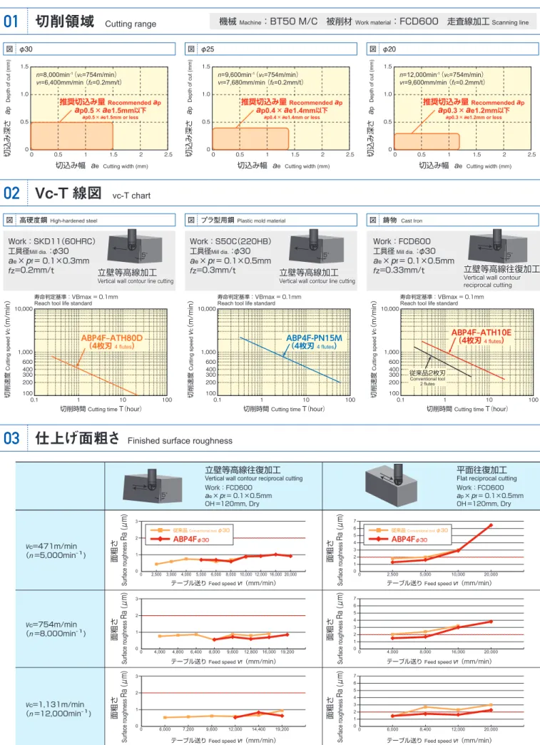
図 φ30 図 φ25 図 φ20
図 高硬度鋼 High-hardened steel 図 プラ型用鋼 Plastic mold material 図 鋳物 Cast Iron
切削性能
Cutting performance
中仕上げ加工面の比較(FCD600)
01
Compared with cutting surface after semi-finishing (FCD600)
01
切削領域
Cutting range
Vc-T 線図
02
vc-T chart
仕上げ面粗さ
03
Finished surface roughness
平面加工における能率比較
02
Performance comparison when cutting flat surfaces
03
立壁加工における寿命比較
Tool life comparison when cutting vertical walls
曲面加工の摩耗比較
04
Wear comparison when profiling
切削速度
Cutting speed
v
c
(m/min)
切削時間 Cutting time T(hour)
100 200 300 400 600 1,000 10,000 0.1 1 10 100 寿命判定基準:VBmax= 0.1mm Reach tool life standard
切削速度
Cutting speed
v
c
(m/min)
切削時間 Cutting time T(hour)
100 200 300 400 600 1,000 10,000 0.1 1 10 100 寿命判定基準:VBmax= 0.1mm Reach tool life standard
切削速度
Cutting speed
v
c
(m/min)
切削時間 Cutting time T(hour)
100 200 300 400 600 1,000 10,000 0.1 1 10 100 寿命判定基準:VBmax= 0.1mm Reach tool life standard
切削条件
Cutting conditions被削材
Work material:FCD600
工具径
Mill dia.:φ30 ATH10E
OH
=150mm
v
c=1,130m/min
(n =12,000min
-1)
a
p×
p
f= 0.1×0.5mm
Dry
切削長
Cutting lengthL=10km
切削条件
Cutting conditions被削材
Work material:FCD600
工具径
Mill dia.:φ30 ATH10E
OH
=150mm
v
c=1,130m/min
(n =12,000min
-1)
a
e×
p
f= 0.1×0.5mm
f
z=0.33mm/t Dry
機械 Machine:BT50 M/C 被削材 Work material:FCD600 走査線加工
Scanning line2 枚刃と比較して加工能率 2 倍です。
2 枚刃と比較して加工能率 2 倍です。
結 論
Conclusion:Double the cutting performance of 2-flute tools
2 枚刃と比較して寿命 2 倍です。
2 枚刃と比較して寿命 2 倍です。
結 論
Conclusion:Double the tool life of 2-flute tools
切削条件
Cutting conditions被削材
Work material:
FCD600
n =8,000min
-1v
c=754m/min
a
p×
p
f= 0.1×0.5mm
Dry
平面往復加工
Flat reciprocal cutting5°
立壁等高線
往復加工
Vertical wall contour reciprocal cutting切削長
Cutting lengt h(m)
2枚刃
2 flutesABP4F
4枚刃
ABP4F 4 flutes0
1,000
2,000
v
f=16,000mm/min
L=2,000m
v
f=8,000mm/min
L=1,000m
寿命判定基準:VBmax=0.2mm
Reach tool life standard加工能
率(倍
)
2枚刃
2 flutesABP4F
4枚刃
ABP4F 4 flutes0
1
2
v
f=16,000mm/min
f
z=0.33mm/t
v
f=8,000mm/min
f
z=0.33mm/t
Processing performance (multiple)
0 1 2 3 4 5 6 7 0 2,500 5,000 10,000 20,000
v
c=471m/min (n =5,000min-1)v
c=754m/min (n =8,000min-1)v
c=1,131m/min (n =12,000min-1) 0 1 2 3 4 5 6 7 0 4,000 8,000 16,000 20,000 Work:FCD600ap
×pf
= 0.1×0.5mm OH=120mm, Dry Work:FCD600ae
×pf
= 0.1×0.5mm OH=120mm, Dry 0 1 2 3 4 5 6 7 0 6,000 8,400 12,000 20,000 0 1 2 3 0 2,500 3,000 4,000 5,000 6,000 8,000 10,000 12,000 16,000 20,000面粗さ
Surface roughnessRa (μm)
テーブル送り Feed speed vf (mm/min)
面粗さ
Surface roughness
Ra (μm)
テーブル送り Feed speed vf (mm/min)
面粗さ
Surface roughness
Ra (μm)
テーブル送り Feed speed vf (mm/min)
面粗さ
Surface roughness
Ra (μm)
テーブル送り Feed speed vf (mm/min)
面粗さ
Surface roughness
Ra (μm)
テーブル送り Feed speed vf (mm/min)
面粗さ
Surface roughness
Ra (μm)
テーブル送り Feed speed vf (mm/min)
0 1 2 3 0 4,000 4,800 6,400 8,000 9,600 12,800 16,000 19,200 0 1 2 3 0 6,000 7,200 9,600 12,000 14,400 19,200
【注意】
【
Note
】
Ra≦2μmを基準とした場合、上記の試験結果では立壁加工は基準を満足します。ただし、平面加工でRa≦2μmを満たすためには
fz
≦0.25mm/tに設定が必要です。
具体的には、上記データよりn=5,000の時
v
f=5,000以下、n=8,000の時
v
f=8,000以下、 n=12,000の時
v
f=12,000以下を目安にご使用ください。
When Ra≤2µm is set as the standard, the test results shown above satisfy the standard when cutting vertical walls. However, in order to satisfy Ra≤2µm when planing, it is necessary to set fz≤0.25mm.
To be specific, from the above data the following should be used as general criteria: When n=5,000,
v
f=5,000 or less; when n=8,000,v
f=8,000 or less, when n=12,000,v
f=12,000 or less.立壁等高線往復加工
Vertical wall contour reciprocal cutting5°
平面往復加工
Flat reciprocal cuttingABP4F
φ30 従来品 Conventional tool φ30ABP4F
φ30 従来品 Conventional tool φ30Work:FCD600
工具径
Mill dia.:φ30
a
e×
p
f= 0.1×0.5mm
fz=0.33mm/t
従来品2枚刃 Conventional tool 2 flutesABP4F‒ATH10E
(4枚刃
4 flutes)
立壁等高線往復加工
Vertical wall contour reciprocal cutting 5°
Work:SKD11(60HRC)
工具径
Mill dia.:φ30
a
e×
p
f= 0.1×0.3mm
fz=0.2mm/t
立壁等高線加工
Vertical wall contour line cutting 5°
ABP4F type (4 flutes)
従来工具(2枚刃)
Conventional (2 flutes)
工具
Tool:ABP4Fφ30 ATH80Da
p
×
p
f
= 0.4×1.5mm
n =12,000min
-1v
f
=12,000mm/min
Q
=7.2cm
3/min
中仕上げ
Semi-Finishing仕上げ
Finishing 縦 100.0μm/cm 横 2.0mm/cm工具
Tool:φ30仕上げ用2枚刃ボール
For finishing φ30 2 flutes Balla
p
×
p
f
= 0.1×0.3mm
n =12,000min
-1v
f
=8,000mm/min
Q=0.24cm
3/min
工具
Tool:φ30 粗用 2 枚刃ボール
a
p×
p
f = 0.4×3.0mmn =3,000min
-1v
f=3,000mm/min
Q
=3.6cm
3/min
中仕上げ
Semi-Finishing仕上げ
Finishing工具
Tool:φ30仕上げ用2枚刃ボール
For finishing φ30 2 flutes Balla
p
×
p
f
= 0.1×0.3mm
n =12,000min
-1v
f
=8,000mm/min
Q=0.24cm
3/min
For roughing φ30 2 flutes BallSmall pitch and high feed cutting
縦 100.0μm/cm 横 2.0mm/cm
ピッチを細かく
送りを上げて加工
ピッチが粗い
ビビりが 発生 Chatter occurs前工程の加工面が粗いと仕上面粗さに影響します。
It’ s influence to finishing surface roughness when before process is rough.
前工程の加工面が粗いと仕上面粗さに影響します。
It’ s influence to finishing surface roughness when before process is rough.
ABP4F‒ATH80D
(4枚刃
4 flutes)
Work:S50C(220HB)
工具径
Mill dia.:φ30
a
e×
p
f= 0.1×0.5mm
fz=0.3mm/t
立壁等高線加工
Vertical wall contour line cutting 5°
ABP4F-PN15M
(4枚刃 4 flutes)
Rough pitch従来品比、加工能率 2 倍、切削長 3.6 倍の結果が得られました。
従来品比、加工能率 2 倍、切削長 3.6 倍の結果が得られました。
結 論
Conclusion:Compared to conventional products, provides twice the processing performance. 3.6 times the cutting length was achieved.
逃げ面最大摩耗幅 VBmax
(㎜
)
Flank wear
切削長
Cutting lengthL(m)
0
0.1
0.2
0.3
4000
8000
12000
16000
20000
0
1
3.6
18000m
5000m
従来品φ30
Conventionalv
f=5,500mm/min(f
z=0.33mm/t)
v
v
ff=11,000mm/min(f
=11,000mm/min(f
ABP4Fφ30:ATH10E
ABP4Fφ30:ATH10E
zz=0.33mm/t)
=0.33mm/t)
寿命基準 VBmax=0.1㎜に達するまで
To reach tool life standard of VBmax=0.1mm
30° 1.5 1.0 0.5 0 0 0.5 1 1.5 2 2.5