Camera recovery of an omnidirectional multi-camera system using GPS positions
6
0
0
全文
(2) eras and the GPS receiver is always fixed; (iii) the distance between the GPS receiver and the representative camera of the OMS is known, and the direction of GPS receiver in camera coordinate system is unknown. In this paper, it is also assumed that OMS has been calibrated in advance and the intrinsic camera parameters (including lens distortion, focal length and aspect ratio) of each element camera are known. In the remainder of this paper, we first formulate the camera recovery problem of an OMS using GPS positions in Section 2. The implementation of the proposed method is then described in Section 3. In Section 4, the validity of the method is demonstrated through experiments for both synthetic and real outdoor scenes. Finally, we give conclusion Figure 1 A sampled frame of an acquired omnidirectional video.. and future work in Section 5.. Right bottom is an image of vertical element camera.. 2. Formulation of Camera Recovery of Omnidirectional Multi-camera System The goal of this study is to obtain position and posture. Others are horizontal ones.. [ −1. Nic = Mc (M0 ). Ni0 =. parameters of an OMS and a direction of GPS receiver from camera when multiple video frames and GPS positions are. ] Ric. tic. 0. 1. ,. (1). where tic and Ric represent the translation and the rotation. given. The main topic described in this section is how to. from the world coordinate system of the i-th frame to the. integrate GPS position data to the structure-from-motion. camera coordinate system of the camera c. This problem. problem. In the proposed method, the general structure-. is treated as estimation of position (Ri = Ri0 ) and posture. from-motion algorithm is enhanced to treat GPS position. (ti = ti0 ) of the representative camera (c=0).. information. In the general structure-from-motion algorithm,. 2. 2 Error Function for Optimization Process re-. projection error that is observation error is minimized to obtain the parameters. First, we make it clear what the parameters are. Second, as one of observation errors in our problem, the re-projection error is briefly explained. The error concerning GPS, which is another observation error, is then modeled by using geometric relation between camera and GPS. Finally, we describe a new error function combining re-projection error and the error function concerning. Re-projection Error Re-projection error is generally used for camera recovery based on feature tracking. The method for minimizing the sum of squared re-projection error is usually referred to as bundle adjustment. The re-projection error Φij is defined as |qij − q ˆij | for the feature j in the i-th frame, where q ˆ represents the 2D projected position of the feature’s 3D position and q represents the detected position of the feature in the image.. GPS. 2. 1 Position and Posture Parameters of Omnidirectional Multi-camera System. Error of GPS positions Generally, if GPS positions and estimated parameters do. Omnidirectional multi-camera system is constructed of a. not contain any errors, the following equation is satisfied in. set of cameras such as Ladybug (Point Grey Research) which. the i-th frame among the parameters (position ti , posture. can obtain omnidirectional videos as shown in Figure 1. As. Ri ), GPS position gi and the position of GPS receiver d in. mentioned in the previous section, we assume that position. the camera coordinate system.. and posture relations among element cameras are known and fixed in this paper. The positions and postures of all the cam-. Ri gi + ti = d (i ∈ F ),. (2). eras can be expressed as a pair of position and posture of a. where F denotes a set of frames in which GPS positions are. representative camera.In the i-th frame, the transformation. obtained. However, if GPS position gi and the parameters. from the world coordinate system to the camera coordinate. ti and Ri contain some errors, we must introduce an error. system of each element camera c can be expressed by the. vector ni .. following matrix Nic by using the transformation Mc from the world coordinate system of a calibration process to the camera coordinate system of the camera c (= 0, 1, 2, 3...n).. Ri gi + ti = d + ni .. (3). In this paper, we introduce an error function Ψi related to.
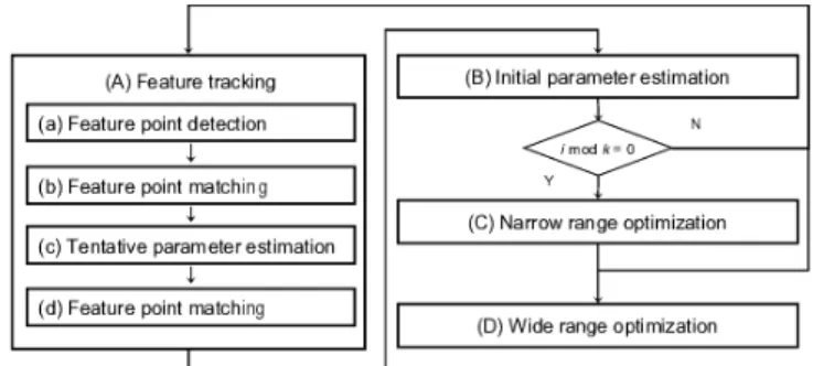
(3) GPS receiver using the length of the error vector n: Ψi = |ni |. This function means the distance between the measured position of the GPS receiver and the predicted one. Next, we describe a new error function E which is a combination of the error function Ψij related to GPS receiver and the reprojection error Φ. Error Function Concerning Feature and GPS The new error function E is defined as follows: E=. ω ∑ 2 Ψi |F| i∈F. ∑∑. 1. +∑ ∑ i. c. Figure 2 Overview of the proposed algorithm.. |Sic |. i. µi. c. ∑. wj Φ2ijc ,. matically detected by using the Harris operator for limiting (4). j∈Sic. where ω means a weight for Ψi , and Si denotes a set of feature. feature position candidates in the images. In the next process (b), every feature in the (i − 1)-th frame is tentatively matched with a candidate feature point in the i-th frame by. points detected in the i-th frame. The coefficients µi and wj. using a standard template matching. In the third process (c),. mean the confidences for frame and feature, respectively. wj. tentative parameters are then estimated by selecting correct. represents the confidence coefficient of feature point j, which. matches using a RANSAC approach [15]. In the final process. is computed as an inverse variance of re-projection error Φij .. (d), every feature is re-tracked within a limited searching. The coefficient µi denotes the confidence of the i-th frame.. area in image frames of all the element cameras, which can. Two terms in the right-hand side in Eq. (4) is normalized. be computed by the tentative parameters and 3D positions. by |F | and. ∑ ∑ i. |Sic | so as to set ω as a constant value c. of the features.. independent of the number of features and GPS positioning. (B) Initial parameter estimation :. points.. This processes computes 3D positions of feature points and. 3. Implementation of Camera Recovery Method of Omnidirectional Multicamera System. position and posture parameters which minimize the sum of squared re-projection errors. In this process, the parameters of the current frame i are computed by using the tracked feature points. The error function Einit defined by Eq. (5) is. The proposed method basically consists of feature tracking and optimization of camera parameters as shown in Figure. minimized to optimize both the parameters ti and Ri of all the frames and 3D positions of all the feature points.. 2. First, two processes of (A) feature tracking and (B) initial parameter estimation are performed in order. At constant frame intervals, the narrow range optimization process (C). Einit =. ∑. wj Φ2ijc .. (5). j∈Sic. is then carried out to reduce accumulative errors. Finally,. (C) Narrow range optimization :. estimated parameters are refined using many tracked feature. In this process, the frames from the (i − (k + 2l) + 1)-th to. points in the wide range optimization process (D). In the. the current frame are used to refine the camera parameters. processes (C) and (D), a common optimization is performed.. from the (i − (k + 2l) + 1) to the (i − l)-th frames, as illus-. The difference in both processes is the range of optimized. trated in Figure 3. This process is designed to use feature. frames. In the process (C), the range of optimization is a. points and GPS positions obtained in the frames around the. small part of the input frames because future data cannot. updated frames. To reduce computational cost, this process. be treated in sequential process. On the other hand, in the. is performed every k frames. Note that the estimation result. process (D), a large number of frames are optimized and up-. is insensitive to the value of l if it is large enough. The con-. dated.. stant l is set as tens of frames to use a sufficient number of. (A) Feature tracking :. feature points reconstructed in the process (B). The constant. The purpose of this process is to determine corresponding. k is set as several frames, which is empirically given so as not. points between the current frame i and the previous frame. to accumulate errors in the initial parameters estimated in. (i − 1). The main strategy to avoid mismatching in this pro-. the process (B).. cess is that feature points are detected at corners of edges by. It is difficult to obtain a global minimum solution because. Harris operator [14] and detected feature points are tracked. there are a large number of local minima in the error func-. robustly with a RANSAC [15] approach.. tion E. In order to avoid this problem, we currently adopt. In the first process (a), natural feature points are auto-. a method to change the weight µi in the iteration of the op-.
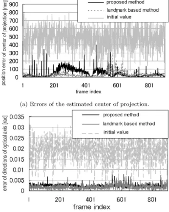
(4) updated frame representative camera i-(k+l)+1. l frames. i-l. k frames. i. l frame. GPS position. optimized frames Figure 3 Optimization in the process (C).. timization, which is experimentally derived from computer simulations. In this method, the weight is changed when-. (a) Errors of the estimated center of projection.. ever optimization process is converged. However, it should be note that there is a room for improvement because the present method is found just experimentally. This implementation is used in the next process (D) (D) Wide range optimization : The optimization in the process (C) dose not provide sufficient accuracy for a final output because it is performed for a part of frames and GPS positions for feedback to feature tracking process (A). The purpose of this process is to refine parameters by using tracked features and GPS positions in wide range frames. The algorithm of this process is the same as the narrow optimization process (C) when l and k are set as several hundred frames except that divided ranges. (b) Errors of estimated optical axes. Figure 4 Error of the estimated position and posture.. are independent of each other.. 4. Experiment. virtual camera takes 900 frames by moving in the virtual environment. The intrinsic parameters of the element camera. This section describes experiments for both synthetic and real outdoor scenes. First, the experiment for synthetic data is carried out to evaluate the accuracy of the position and posture parameters of OMS estimated by the proposed method when the correspondences of feature points are given. The experiment for real data is then demonstrated to confirm the validity of the whole proposed method. Note that some parameters used in the optimization process (C) and (D) were set as follows. The weight coefficient ω in the error function E defined by Eq. (4) was set as 10−9 . The weight µi of the corresponding frame was always set as 1.0, when a GPS position was obtained, When it was not obtained, 1.0 and 2.0 were alternately set as the weight µi whenever the optimization step was converged. In the narrow optimization process (C), we set the number of updated frames k = 5 and the number of optimized frames 49 (l = 22). 4. 1 Synthetic Data The purpose of this simulation is to evaluate the parameters ti and Ri estimated in the wide optimization process (D). In addition, the validity of the proposed method is confirm by comparison with the conventional method [8]. We gave a point set as a virtual environment that was used to generate 2D feature positions in synthetic input images. The. in the virtual OMS are set the same as the real camera described in the next section. The position of GPS receiver in the representative camera coordinate system is set as (60,150,250)[mm]. We added errors to input data as follows. The GPS positions with Gaussian noise (σ =30 mm) are given every 15 frames. The feature points are projected to the virtual camera, and detected with Gaussian noise (σ =1.6 pixel) and quantization error. The initial parameters are generated by adding Gaussian noise (position: σ = 500 mm, posture: σ = 0.020 rad) to the ground truth. In the compared method [8], all the frames is set as key frames in which more than 15 feature landmarks appear. The landmarks are given as feature points whose confidence coefficient is set as large enough, and the 2D positions of the landmarks in each frame are given without any errors. Position and posture errors in the simulation result for the synthetic data are shown in Figure 4. In the compared method, the position error is 47.5 mm, and the postures error is 0.0019 rad on average. In the proposed method, the position error is 30.7 mm, and the posture error is 0.0023 rad on average. These results indicate that the proposed method enables us to obtain position and posture parameters of OMS in the.
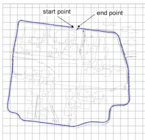
(5) Figure 5 Omnidirectional multi-camera system and GPS receiver.. same order of precision as the conventional method without any manual acquisitions of surrounding information. The difference in the accuracy between the proposed method and the. Figure 6 Horizontal trace of omnidirectional multi-camera system on the environment map.. compared one can be caused by the difference of the effect of the given absolute position information such as GPS positions and landmarks. Concretely, the reason why the posture errors are smaller than the position ones is that landmark position information obtained from images is more sensitive to the estimation of postures than GPS position information. 4. 2 Real Scene The purpose of this experiment with real data is to confirm the validity of the proposed method which includes the. quence. The ranges of divided sequences are shown in Figure 9. The difference of almost all of frames are smaller than the accuracy 30.7mm shown in the previous section 4. 1. This result indicates that we can deal with more long sequences by dividing the sequences if the range parameters k′ and l′ are set adequately.. 5. Conclusion. feature tracking and the error models of feature point detection. In this section, we first describe the condition of the experiment. After that, two kinds of experimental results are shown. In this experiment, we used Ladybug and a GPS receiver (Nikon LogPakII, horizontal accuracy ±3.0 cm, vertical accuracy ±4.0 cm) fixed on an electric mortar vehicle (see Figure 5). We acquired 7200 frames and GPS positions while the vehicle was moving 1.0km distance at 7.6km/h. The acquired frames and GPS positions were manually synchronized. Ladybug was calibrated by using the method developed in our previous work [16]. The distance between OMS and GPS receiver is 300 mm which is manually measured. Figure 6 shows the estimated positions of Ladybug after the wide range optimization process (D). In this figure, the camera path is smoothly recovered and lies around the road. The match move using the estimated parameters is also demonstrated in Figure 7. The virtual cube in Figure 7 seem to be located at the same position in the real environment in most part of the input sequence. We have confirmed that estimated parameters do not contain fatal errors from these results. In the last experiment, we confirm the result of optimization of divided sequences of the wide range optimization process (D). Figure 8 indicates the differences in estimated positions of the OMS between divided sequences and single se-. In this paper, we have proposed a method to estimate positions and postures of an omnidirectional multi-camera system without accumulative errors from image data and coordinated GPS positions. In the proposed method, GPS position information is used for both feature tracking and optimization of position and posture parameters of the omnidirectional multi-camera system. We have confirmed that the proposed method allows us to obtain extrinsic parameters in the same order precision as the conventional shape-from-motion method using a large number of landmarks if GPS positions are obtained well. We will investigate the case that the number of GPS positions including large errors is more than current experiments. References [1] S. Chen, “QuickTime VR: An image-based approach to virtual environment navigation,” Proc. SIGGRAPH ’95, pp.29– 38, 1995. [2] C. J. Taylor, “VideoPlus: A method for capturing the structure and appearance of immersive environment,” IEEE Trans. Visualization and Computer Graphics, vol.8, no.2, pp.171–182, 2002. [3] M. Uyttendaele, A. Criminisi, S. B. Kang, S. Winder, R. Hartley, and R. Szeliski, “High-quality image-based interactive exploration of real-world environments,” IEEE Computer Graphics and Applications, 2004. [4] A.W. Fitzgibbon and A. Zisserman, “Automatic camera recovery for closed or open image sequences,” Proc. 5th European Conf. on Computer Vision, pp.311 – 326, 1998. [5] M. Pollefeys, R. Koch, M. Vergauwen, B. Deknuydt, and.
(6) 610th frame. 630th frame. 650th frame. 670th frame. 690th frame. 2720th frame. 2740th frame. 2760th frame. 2780th frame. 3000th frame. Figure 7 Match move using estimated position and posture parameters of Ladybug.. [6]. [7]. [8]. [9]. [10]. [11]. [12]. [13]. [14] [15]. [16]. L.V. Gool, “Three-dimentional scene reconstruction from images,” Proc. SPIE, pp.215–226, 2000. S. G¨ uven and S. Feiner, “Authoring 3D hypermedia for wearable augmented and virtual reality,” Proc. 7th IEEE Int. Symp. on Wearable Computers, pp.118–126, 2003. A.J. Davison, “Real-time simultaneous localisation and mapping with a single camera,” Proc. 9th IEEE Int. Conf. on Computer Vision, pp.1403–1410, 2003. T. Sato, M. Kanbara, N. Yokoya, and H. Takemura, “Dense 3-D reconstruction of an outdoor scene by hundreds-baseline stereo using a hand-held video csamera,” Int. Jour. of Computer Vision, vol.47, no.1-3, pp.119–129, 2002. ´ Marchand, and F. Chaumette, “A realA.I. Comport, E. time tracker for markerless augmented reality,” Proc. 2nd ACM/IEEE Int. Symp. on Mixed and Augmented Reality, pp.36–45, 2003. L. Vacchetti, V. Lepetit, and P. Fua, “Combining edge and texture information for real-time accurate 3D camera tracking,” Proc. 3rd IEEE and ACM Int. Symp. on Mixed and Augmented Reality, pp.48–57, 2004. Y. Yokochi, S. Ikeda, T. Sato, and N. Yokoya, “Extrinsic camera parameter estimation based on feature tracking and GPS data,” Proc. Asian Conf. on Computer Vision, pp.369– 378, 2006. D. Nist´ er, O. Naroditsky, and J. Bergen, “Visual odometry,” Proc. IEEE Computer Society Conf. on Computer Vision and Pattern Recognition, pp.964–971, 2004. Z. Hu, U. Keiichi, H. LU, and F. Lamosa, “Fusion of vision, 3D gyro and GPS for camera dynamic registration,” Proc. 17th Int. Conf. on Pattern Recognition, pp.351–354, 2004. C. Harris and M. Stephens, “A combined corner and edge detector,” Proc. Alvey Vision Conf., pp.147–151, 1988. M.A. Fischler and R.C. Bolles, “Random sample consensus: A pradigm for model fitting with applications to image analysis and automated cartography,” Communications of the ACM, vol.24, no.6, pp.381–395, 1981. S. Ikeda, T. Sato, and N. Yokoya, “High-resolution. Figure 8 Difference of the estimaged positions from between divided sequences and single sequence. 1950. 0 0. 1949 1750. 1950. 1950. 5850. 7800 frame index. 2150 3899 3700 3900. 3200 5849. 6050. 5850 7799 updated fame 5650 optimized frame. Figure 9 Range of optimization of divided sequence.. panoramic movie generation from video streams acquired by an omnidirectional multi-camera system,” Proc. IEEE Int. Conf. on Multisensor Fusion and Integration for Intelligent System, pp.155–160, 2003..
(7)
図

+2

関連したドキュメント
Recovery of the Rare Metals from Various Waste Ashes with the Aid of Temperature and Ultrasound Irradiation Using Chelants.. Hiroshi Hasegawa,* , 1
Therefore, we considered the heat conduction effects concentrated around the heat extraction pipe embedded in the bamboo chip pile, and obtained relatively simple analytical
In this paper, the surface temperature of the powder mixture in metallic additive manufacturing during laser beam irradiation was measured by two-color pyrometer employing optical
1) Tamaki N, Cuidlines for clinical use of cardiac nuclear medicine (JSC 2005). Neuronal imaging using SPECT. Eur J Nucl Med Mol Imaging. Role of MIBG myocardial scintigraphy in
Keywords: homology representation, permutation module, Andre permutations, simsun permutation, tangent and Genocchi
Moreover, to obtain the time-decay rate in L q norm of solutions in Theorem 1.1, we first find the Green’s matrix for the linear system using the Fourier transform and then obtain
This paper focuses on the study of the influences of random phase on the behaviors of Duffing-Holmes dynamics and shows that the random phase methods can actualize the chaos
Applications of msets in Logic Programming languages is found to over- come “computational inefficiency” inherent in otherwise situation, especially in solving a sweep of
