Architectural Institute of Japan
NII-Electronic Library Service
ArchitecturalInstitute of Japan
[su
N] . ・, .・ JeurnaLef Strueturaland ConstTuctipnEngineering H"ftev\ftMuskdescvazaff UDc:6g. o22 ':bgg.lj41
:6g. o2s. 22:sso. 344 (Transaetions ef AIJ)No.377,Julv,lgB7 ・ rg377 g-wa" 62 'ny7fi'
'. .
1 /.
tt/ '
tt
EFFECTS
tttOF
MONOLITHIC
tttFLOOR
tttSLABS
ON
ttTHE
t/t/MECHANICAL
BEHAVIOUR
OF,FRAMED
SHEAR
WALLS
t t
t t
SUBJECTED
TO
EARTHQUAKE
LATERAL
LOADS'''
'' '
. . . .・
by
Masahide
TOMII',.
Tetsuo
YAMAKAWA"!
.and
Toshiharu.
NINOMIYA+,",
Members of A.I.J.,/, , . ,,/ .
1.Introduction,.- .., . . , ,. ,
Itisconsidered thatone of the necessary stttdies foraseismic designisto discussthe effects of floorslabs.on the
mechanical
behaviour
of framedshear wall(hereafter
refeFred to as."shear wall") subjected toearthquake late.ralloads,since the shear walls arranged inthe reinforced concrete framestructures are monolithic with floorslabs.,The monolithic fleorslabs
(hereafter
referred toas "floor-slabs") transfer theeqrthquake lateralloadsasdistiibutedloads on the
beanis
adjaceqt towall panel(hereafter
referred toas "beams").Also
theaxial,flexura.1
and shearing stiffnessesof beamsare enhanced bythe floQrslabs. Inthispaperthe effects of floorslab on the,angulardistortionof thecolumns adjacent touncracked wall panel(hereafter
referred to as・"columns"} are discussedusing analytical solutions(concerning
shear walls) expressed intermsof Fourierseriesi).Oneaspect ofthediscussionconcerns withthemechanism forapplying the lateral
load
and the other with thestiffness evalqation of beams. As aconsequence the nodal stiffness matrixZ) of sheqr wall, considering the effect oftfloor slabs, iscalculated(as
presentedin numerical examples) inorder to analyze frame structures stiffened with monolithic wall panels using matrixdisplacementmethod,
On the other hand, when the diagonalshear cracks occur inthe vvall panel, the wall panel becomesas an anisotropic platehavingand behavesthediagonalcompression fieldbyshear, and
beams
and columns, togetherwiththefloerslab, restrain thedilatationofthecracked wall panel.Thus the cracked shear wall exhibits complicated
mechanical behavioui.The elastic analyses of thesingle-bay single-story and thesingle-bay two-storyor two-bay single-story cracked shear walls
(hereafter
referred to as "single shear wall" and "2-continued shear wall" respectiyely) havebeenreported by Torniiet al.3)'5),assuming the walls to be 45-degreeorthotropic plates. Inthispapertheelastic analyses of uncracked and cracked reinforced concrete shear walls infinitely continuous inone or two directions
(hereafter
referred teas "infinitelycontinued shear wall") as weH as thoseof single and 2-continuedshear walls are performedusing Airy'sstress functionof 45-degreeorthotropic elastic plates.And the effects of monolithic floor slabs on stress resultants and deformations of the beams are clarified,
2.The Effectsof MonolithicFloorSIabson Angular Distortionof UncrackedShear Watl
Inorder toexamine theeffects of floorslabs, the angular distortionsof single-baysingle-story and single-story infinitelybontinueduncracked shear walls subjected te'earthquake lateralloads
(as
illustratedinFig.1) arediscussedinthefollowingfourcases.
I:Lateralloadsare applied as uniform distributedIoadstothe axis of thebeams, where flexural,shearing and
axial stiffnesses of the beams are real.
ii:Lateralloadsare applied as cencentrated loadstothenodal pointsat fourcorners of theshear wall, where flexural,shearing and axial stiffnesses of the beams are real.
iii:Axialstiffness of thebeams isassumed toberigidi, while flexuraland shearing stiffnesses of thebeamsare
real.
* D. Eng., Professor,Kyushu University.
# M. Eng.. ResearchAssociate.KyushuUniversity. """ M. Eng., Structural Engineer, NikkenSekkeiLtd. {Manuseiipt received becember 10,1986)
-102-Architectural Institute of Japan
NII-Electronic Library Service
ArchitecturalInstitute ofJapan
h
Concentrated loads Di$tributed loads
Single-bay single-story shear walLs
Fig.1 Uncrackedshear
Table1 The aspect ratios of single-bay
numerieal examples Q e Q - - -> ' e - <-Q Q Q
e
e
' ・ e'Q ' t/Concentratedloads 'Distributed loads
Single-storyinfiniteLy continued shear waltg
walls subjected to earthquake lateralloads
single-story shear wall or unit shear wall adopted infiye
Aspectratios'x ab
Bb
%Bc
No.11.714 O.171 2.5 O.171 3.333
No.2O.5 O.3 4' O.2' 4
ericalmples'No.31
O.3 3 O.2 4
No.42 O.2 3 O.2 4
'
Ne.53 O.1 2 O.2 4
Note: The proportion of the shear wall adopted as example No. 1
(see
Fig.fordefinitions of
espect
ratios of shear wall} is equal to that of theshear wall adopted as the designexample shown inthe AIJ Standard
StructuralCalculqtionof Reinfo,rcedConcrete Structures
(revised
in1982).
iv
:Axial stiffness of thebearnsisassumed tobe
rigid, whileflexural
anclshearingstiffnesses of the beams are increased
together twiceland fivetimes:
Thenumerical calculations of angular
distor-tions forfiveproportionsof shear wall
(see
Table1) are carried out''for each cdse
men-tioned above.
(See
Fig.2fordefinitionsand aspect ratios of each unit shear wall.) The results are presented i.nTables2and.3, IfiTable2,the values shown inthe.columns with
headingsRilR'm and RiilRtiiare ratios of
angular
distortions
inducedincasesi
andii,
coefficient x'.of the angular distortionsof th xtsQl(Gtl). Noticethatthe angular
dependenton the preportionsof shear 'walls
No.3).Thissu
case iiare used. Alsothe
shear wall incase ・iimay become remarkable smaller.' However the angulat distortionsin are nearly equal to those incase iii
(see
Inorder todiscusstheeffect of floorsla case ivtothoseincase
iii
, where flexuralanrh
L
: 'Qc,H
respectively,e shear wall incase
distortions
(compare
ggeststhatthe actual angulhr distortionsof
discrep.anciesbetweenangular distertionsof as
case
Table 2)
bsen angular distortiensof shear dshearing stiffnesses
e
''
Fig.'2.C6nfiguratio4and aspebt '
'
tothoseincase
iji
.iii'
of qolumns inease
ii
arerbuch
numerical 6xamplesNo.1,
cloumns will beoverestimat6d
columns an
thespan lengthbecomeslongerand
j
are almost uniwall,
of the'beamsare' '
abI
{
u
Ibc
2 for x =ft ab"?%.
b,b Dc(c=T'
bcBc " tratios of each unit shear wall
Inthistable,R,,,represents the where the angular distortionsare computed as
largerthan thoseincase iand
No.4and No.5with No.2and iftheangular
distortioRs
in dthose definedat midspan of thetheaxial stiffness of beam
formthroughouttheshear walL and these values
' ' '
the ratios of angular distortionsin
increased byenlarging the
beam
-Architectural Institute of Japan
NII-Electronic Library Service
ArchitecturalInstitute ofJapan
Table2 Ratios RilRm and RiilRmof angutar distortiensof theshear walls
'
'Single-'baysingle-stQryshearwalLS,Single-storyinfinitelycontinued
shearwalls--' Locations Column Midspafi Ri"ag Column
,Midspan R.H111(2 Ratios t. Ri/R;-[,Ri・,/Rili 'Ri/Ri" 'Ru/R;;;(n.tZ)Ri/RiilRii/R.iii,Ri/R"iRil"/Riii,(GtZ) iNo.1O.991.361.00O.75O.811.001.38O.99O.7SO.79 No.2o.9g1.,.1.001.00.O.9,9..O.46O.99tt1.001.00' ,P.9,9 'O.48 opo-aEasx'o-es.ytsE=z No.3O.99il.OS'-l,OOO.94O.61O.99'・・1;051.00O.94O.61 Nb.4O.991.39O.99O.73O.761,.OO1.40O,99O.73O.76 No.51.002.94-1.00-O,12O.871.02 '3.04 '1,Ol-O.13O.86 '
Note: 1)Riisthe angular distortions of the $hear wall subjected to lateral
uniform distributed load e・incase i.
'
2)Riiisthe. angular distortionsof.the shear
ivall
subjected to Iateralconcentrated loafd
ap
in case ii. . ・3)Riilisthe angular distortionsof the shear wall subjected to lateral load
Q
in case iii.4>T,h,Y..",ai:?S,hS.hP.W.".fif",,l,O.i:,M",.W,`t.hf?:.adL",gg.IR,,i"idi,?8?,iC.O.r,re.SfPO,"h/`n,gh.t.O,the
wall incase iii,inwhich the values of Ri;; ate computed as KdiQ/(GtZ)
, where G is modutus of elasticity inshear, 1.tisthickness of wall
and
Z
iscenter-to-cenrer distanceef columns'.of the shear walLt ttt t t t t ' t ttt tt t t ' t tt tt t t t t '
Table3' T.heef.fectof'the width of bearns'ontheraliog RtJZRattof,ang'ular diFtoltions
/t t ttt tt t t t t t tt tt '
Note :1) Rii'iisthe angular distontionsof shear,walls iny case
ili,
where the'beain width tb ]vallthickness rati6 'Bb` is2;'5.' ''
2)lRi, isthe angular distortiops of shear walls in case iv,'- , './
t t.
Y2h.es're
'thebeam width to wal'! thicknp,ss rat,ios.Bbs
are 5..Oand.・ ・ '3) ¢ ・ 'is''therate of・ enlargement for.thewidth of beam$. ・'''・
.t .t/. . .t. /
/tttt t .t /t . t. t/ // / /./ltl.
width,
qteprovided,,as shown ,inTable3..Thistable shows,,th4t ,the ,effectisgenerally・small,''Con.sequgntly,theaxial stiffness of the,beams can be,assumedto berigid, in
distributedthrough thefloorslabs are tre4ted.asconcentrated loaason the・noda
F,hearw411s. Thi.sresult is..usefulin,,thefprmula,tionof the Qedal stiffness-matrix of the shear
3.
The results discussedinSection2,suggestthattheaxial stiffness of thebeamscan-be assumed tQbe
formulationof the fundamental nodal stiffness matrix Ki of u.ncracked shea,r wall,
(see
Tables
4 and s) isqerived
,asthe analytical selutiops, a genera! stiffness mqtrixk
of shear walls is easily by making use of transformationmatrix2).Note
,thatTypesI,
ll,
--
104
-'Numerical .tSingle-baYshearwallsingle-storyt/Single-story
continuediri'finit'elY'shearwalls examples/
th-.2 ¢ -5
.O-2, ¢ =5
No.1 o.97 O.95 '
O.97 'O.9.5.
'',No.2'o.93 'O.88
O.95 O,.92tt
No.3 o.93 O.88 oLgsL 'o'.9i
No.4 o.96 O.94 tt.0.97 'O.95,/ttt
No.5 o.98.
'O.97' O.98 o..,9''7'
'
t//t t t.t
'
case theeatthquake lateralloads
1
pointsatfourcorners of ungrackedwall.
Numerical Examples on Fundamenytal'Nodal
$tiffne$s
Matrix.
ctSingte Shear,Watl.Restrained byFloorSlabrigid inthe
Ifeach K" .of
fundamental
type formulatedM
andrv
to b,ementioned・below・.are,theArchitectural Institute of Japan
NII-Electronic Library Service
ArchitecturalInstitute ofJapan
basictypesof the
fundamental
compenents of nodal forces'and
nodal displacementsof theshear wallsZ}.
Thefundamentalnodal stiffness matrices K:of Type [ and Kreof Type
rv,
whose components are symmetric withre$pect tothelongitudinalcenter line of the wali panel, can begiven approximately bypin-jointing rigid bars at the nodal points of the shear wall along the beams,Thesestiffnesk matrices are treatedas approximate solutions
pertainingto the stiffness matrix of the shear wa!ls with rigid floorslabs
<see
Tables4 and 5),'
Table4
'
-.
The representative components P* and PO of the balancing and unbalancing fundamental components of thenodal external forceson singLe-bay single-story shear wall
I-1 I-2 I-3
TypeIy.tSExSi".xt,
"u43S'fl
'
,gk
*i)Ca
p
Mi ll-1 ll--2 ll--3TypeII."zzzE
fti
LZ"t"Yk.
EZZ,
""
M".CEZ)
M-1 M-2 M-3TypeIIIgm
;
xin"
va'tL
tYk.
CZZZ)
Mfu
IV-1 IV-2 IV-3
TypeIV;vatY
t-Yft
m""
Cva3
ytrv
Note:1} Nodal forcesinparenthesesare dependentfttndamentalcomponents parenthesesare independentfundarnentalcomponents,
2) Syrnbol * denotesbalaricingfundamentalcornponents. 3) Symbol o denotesunbalancing fundamental components,
and those not in
Table5The numericalexamples of thefundamental stiffness rnatrixK* of single-bay single-stoiy shear wall
Fundamental type Type I" Type II
Type
III Type IV Neglecting rnonolithic floorslab 4Xt4Yf.Et[3.oes
(
sym.g';l:jl:i・4Xft4Yft4Millh=Et3.854O.4S3 -O.197
sym.7.626 O.362O.170 ui vtiheft
{
4Y*m4Mli,1,ll.,,[ '.g;2:,3g,s]I,glll
{
4Xft4M"ivlhl-Et[3.:.2i 'gl:l:]I,:lrl
Correction term for
considering ,
monolithic floor slab
(i:til-E,[
O.761sym.:'ill)I:lll 4Xil4Y *I4Mti/h=Etkbn o o sym.ooo uft Vdeihei{i,X
il,,l
-Et[ kdnsym.:
]Ih:l'li
Note: kbll'kdn= oo
-Architectural Institute of Japan
NII-Electronic Library Service
ArchitecturalInstitute of Japan
Sincethereis no late:alloadstobalancethe system inType
M
(see
Table4),the effect of, floerslabs,on KM maybe neglected. The lengths of the bearpsdo not change bythe nodal displacements of Type,I.Thereforeitis rpeaninglesstopin-jointing rigid bars at the nodal points ef the sheqr wall along thebeamsfor considering the effect
of floorslabs. Asa result, only theanalytical solutions of Kr are required, where theaxial stiffness of thebeamsis
assurnecl to berigid. Inthispaperthe analytical solutions of Kr of theshear .walls with floor slabs are obtained, and
after that,thecorrection term to beadded to KI of the shear walls without flooislab isderived.
Numerical examples・ forK" of thesingle shear wall are presentedinTable5.The proportionof the shear wail is eqtial to that shown inthedesign example inthe AIJStandard
for
Struct'uralCalculation ef ReinforcedConcreteStructures
(revised
in1982)(see
Fig.2and shear wall No.1inTable 1).Poissonratio isassumed to be1!6.4. ElasticAnalysis ot Cracked Shear Watl lnfinitetyContinuous in・One or Two Directions
The elastic analyses, bywhich mechanical behaviourof single and 2-continuedcracked shear walls was clarified assuming shear cracked wall panelsas 45-degreeorthotropic plates,havebeenreported
by
Tomii et al.3)'5).Inthispaper,the analysis isapplied toanalyze cracked shear wall infinitelycontinued in one or two directionsand
subjected to external forcesthatare polarsymmetric with respect to the centers of the wall and theintermediate member
(see
Fig.3).Sincetheassumptions ahd methods intheelastic analysis of thispaperarethesame as those of single and 2-eontinuedshear walls3]-5), except foreqllilibrium equations on horizentaland vertical cross sections of unit shear walls(see
Fig.4),detaileddiscussionson the analytical methods 'andthederivationsof equations are omitted. The two typical characteristics aTe as follows.''
i
)
The deflectionof intermediatemembers isexpressed byodd functionsand a,constant. The odd functions'
represent flexural
'and
shearing deformations of the intermediatemembers. The constant represents the rigid-body displacementof intermecliatemembers duetodilatationof theshear cracked wall panel. Therefore,if
the wall panel isah isotropicelastic plate,thedeflectienof each intermediatemember isexpressed byodd
functionsonly. .
'
ii
)
Theaxial deformationof each intermediateraember isalso expressed byodd functionsand aconstant. Inthiscase, theodd functionsrepresent theelongation of each intermediatemember duetothedilatationof thecracked wall panel and the constant represent therigid-body displacement.The odd functionsare not necessary to express the axial deformationof each intermediatemember whose adjacent wall panelsare isotropiceiastic plates.
[SHEAR
WALL 11[SHEAR
WALL 2]---.-1'
M.-"
・, ---.1/e-g. .-.--f/f-
g.
--."T-""e.2Lh
eh zTl"-
T
---1 hieh
`lli
i
±
l-T-
-L-:ojtL
zQh7
"・N
-
zg{a)
Single-bay infinitelygontinued
shear wallNote:1)
2)
Fig.3 Infinitelycontinued shear
-106-t
,
t
!
,
-,t
eh-' z ah"' z eh-T /,,te1Y,`1,Y1,1,1"fe---v・:-J.M--`e----J/-.---
-
z- .
(b)
Infinitelycontinued shear walls Theunit partsmentioned bythe thick brokenlines are analyzed.s/
Externalforcespersingle-bay are illustrated.
walls havingshear cracked wallpanels and their external forces
fNt?h
iTTA
hi QftiT-L
Architectural Institute of Japan
NII-Electronic Library Service
ArchitecturalInstitute of Japan
tN
Mb ---L-,>O Mbe".""-
t.
2
tXY=
-#2:Z
r
i,
hgLh
zL,Q.eer.t,rff..tXg Mtr
e<--T--
Alt, .LN・t
x`
1Cin'-t
glhlrubeLe"iT..,.t+
V Tti .-, N 1 --!-)e
eva
ic+
NCI.k
-# y x'"k7txy'
e <--rp-
J,N
ah
t-
T-qcf
÷
Fi"ZebNbi
FTtc,
,iiis"
1Ih,,1
t ' t bc
" -:'
liil3.I[be
r etpo
{a)
SHEAR WALL1{Q=1,
ru=O){b}
SHEAR WALL2(Q;1,
N=O)SHEAR WALL 1'
(Q=O,
N=!} SHEAR WALL 2'(e=O,
ru=1)Fig.4 ThebeundaTystresses and external forcesof the unit paTtef infinitelycontinued shear walls
Intbenumerical exampl.es, the elastic analyses are carried out forthe infinitelycontinued shear wall whose single-bay single-story unit partshave the same preportions・asthose forthesingle shear wali adoPted inSection3.
The elastic constants of the cfacked wall panels are given byEqs.
(
1>-(
4>5].
Ei=("t+n(Pd+2(:,Cill;l,)Psl]cE "'''''''''"''"''"L''"''"''"''''''-''-''H''''''H''-H・・-・・H・"・・・J・・-・・-・-( 1
)
'Ei ==[ptc+nlPd+2("".`iPn;.) Ps])cE '''--'-'"''-''''''-'''"'''-'"'''''''''''''"'''''''H''H'・-・-・・-・・-・・-・・・(2
)
G.= "il+2nPS .E .H.,-,.,,",,.,.H,,.,.,.,...H...H..k.,H,,m,.,.,.-,.",.".,..,...."..H...k...,...,,H,,"
(,
3'}h=
ftt
M={i ,."・,--・--・・・-・・-・・・・・",,-,,.,t,.,,".,・-.,--・`.-,,-,,.,,-".,.,・・--・・--・・・-・・・-・・・-・・-・・---,-Hk.・・・.,.",.,.,(4>
whereE,,E2:Young's modulus forthe principaldirection1of elasticity of the wall paneland that forthe principal
direction2 of elastieity of the Wall panel
Gi!:shearmodulus in the rectangular coordinates 1and 2of the wall panel
n :modular ratio
(n=
.ElcE=10).E :initialYoung's modulus of concrete .E :Young]smodulus of thereinforcement
p. :ratio of diagonalshear reinforcement area to the gross concrete'area of a diagonalsection
(pd=O}
p.:ratio of horizontalor vertical shegr reinforcement area te thegrossconclete area of avertieal or horizontal section
(p.=O.
O025)ut : rediuction coefficient of the Young's modulus bf concrete inthedirectionperpendicular tothe cracks inthe, wall panel
(i.
e. intheprincipaldirectien
l of the wall panel)pt.:redution coeffcient of the Young's modulus of concrete inthe
airection
of the cracks inthe wall panel(i.
e. in the principaldirection2of the wall panel)(".==1)
gn :reductiofi coefficient of the shear modulus of concrete inthe rectangular coordinates 1and 2of the wall panel
(#i!==pte}
-
107
Architectural Institute of Japan
NII-Electronic Library Service
Architectural Institute of Japan
Thebeam-to-columnconnections are given by Eq.(5). ''
E=E,, G=::;E・・・・・・・-・・:・・・
'
are assumed tobea rigid
Fig.5The deformattonsat the bounda[ybetweenwall and frame[SHEAR WALL ]]
,.
t/. - /
Fig.7
ttThe fiheqring
stress tc.ipthe.wallan.d.
t4eshgaring
forcesQband Q.on the cross sectien of
{he
frame[SHEAR
WALL 1]'
zone,Theelastic constants of the beamsand columns
'
","."."HL"H-:Li."H"."""hH"H-{s)
Fig.6The deformationsat the frame
[SHEAR
WALLbound4fy2]betweenwalland
Fig,8The she.aring stress lt. in forcesQ,and Q.on the
[SHEAR WALL 2] thecrosswal]and sectlenthe shearing of theframe Nb(tenston} Nb(tenston> ' t''"tt't
-r.:..・,.iii'・,T;,ti',f:.・:::・{.;・,'i'1'i・f,'.'・`.i-,'S':・,,tL.:'tT.it..t:,'t・t.・.l,.f.,L..:;itV:':i.:f:"t.i./.itt.F;.l:t" ,,.fi,i.",i-l.,",.r・va&'-i#.L・=.i't-1・i-g'"...S"'・・,-";."ti:-1.i.:..,.・.--,--:;r--・f・/":.:::・,i.t,.X・;,・lt・i,,tltk--:#-ig,.c・trt.,l,,,.r.;g,F.i"・i,t. ..
' ' l..L..t= i'l, Scele:ox,wO.ttiiS(
£
tT OO.S1 Nb.Nc- (q) .-tttt'///L・ii"-I,{:s,:S,Ii・l ut=o ----utgO.1';'"itli':'rFt・'.e=:'t'":・l:lt''tJttt.t.:.ttt:lil,li:j,・.4・1.Ltt-""'i.t..:tt:'::L'1,,.,L.[:ti.:.:.tt./.:.:.1.:.t:1:::i:r'!T,:.'tttttttt:;tttttttl"tt.tttttttttScale:/':ili
....veOttt11'5(ilhTlilj'i mb,NcOttti(e)i'i',,a..L:. "t-o -'--・Ut=O.1'r'i"'.'t::':f:.r.xt:../;.:.;:t"..:."=.:.tl;r.;:/-" tt:3,S".:fr・・''t'is,,tt.1: ---'"Ut=1 l ny--Ut=1
i
' :LL-ms.,'-:ri..L-,・t:'・t:-!:.,・;;;:.t",ti,zl;k-1:,t・IiJ:'i:it,:..,・t・:tl-r-tt・,:・tlli.e..:.i'I=/Lt.x,.・tii,:,.t.ijL'l:-/,lt/Vglt-.i,l-.tll.-Tg.-':.U.".e-・: :"t':':'iICriNt.;':t':tt.ttt'lz・L!t:t.:::t/":":f.:.:t.t:t-:'l,.Fh..tjtt::-r-t.-=-A-- ' L"iV..i.imah,':..'l;..ime.',-t.:'.l..il'it J/t,--1;.ft;i',,s,,r..:. ve(eompresston)tt1:1/-.-1;;,Flt'.::li.//1;i"'1' ''a::(campression)Nc(tens ±on> 't :f4,'ii"Yl::'l'],・.l・・r・1.'E!t""t"fEs-r l.,.t':':.::::s:':"i"gi;1,:,1..."'t -)-{・./.,::.=!c.L::..:'.:"'t":'i';ttttt/Z,Z・・L,1,・J-・f,・:-,t-・{ %(compression)E',,}i.Ij・tttUx(eompTesston)'Nc(tensten)'.L,;:Ltttttt'.]stLtt".::::F!.,rt;':i:t:.z:i't-tt:ttt;:tt:t ' ].ixT'lt;tn:;:='t'I\'=Jrt"'l-ttrt-xtt・-'・-,'t・.,・,,,;:i',':.・=s'fitl・:.i:]-',・"t-':.l:!i・:,.,.'.',t.1-t't:.'.・i・l-t::}';・91S' ' ...-..=.tf4Sl-'.."ttr:'tt,T-.=,.,..[..,T,7M,t,.-igt'.':'tL'S,T,f:.ii:tr:pt1-ti・,,';;'l,ltt'・IE:-',4:・;'l・tt,','.-I.i,tf;:.i,:'tt,t':'tL;L:/.t:?・ig・`g,・itL;.,,'t"・i・:
' ' ' lFig.9 The normal stresses ay and a, inthe wall and the axial forcesNb and N. on the cross section of.the frame
[SHEAR
WALL 1]108
-Fig.10ttThe normal stresses ele and eb in the wall and the axial forces'N,.andM'on the cross section ef the
frame [SHEARWALL2] '
Architectural Institute of Japan
NII-Electronic Library Service
ArchitecturalInstitute of Japan ' ' ' tt li・ ÷ -t・'/-'・.trt.:L,:--../,:.・1;:,.-.tEl/-r・i'-/,,・",/''
I-N
- vt;o v ,r 1i:lfiifi.,,tig!--".th・・;:--・tkt-il.g・:"f-,Ls・l.siii
---- ' ut=o ' Ut=O,1Ptn12(fFt)' ---Alv .:ii.'t'-・',tt,i"f.v・:-・i・:-;・:;・'-・::':;''"・ -- Scele:O1--.-N.ix--'LN tv.tt:t-Lt-sttt-t'' i;.{;t'tttl/{'g,2tii,i::;"t-':'is'u'.・--"・utnO.1 -Ut=1") Scale:O12,N, - sTt' 4.L4,;:;・・;l-'S:,iL"Tt,...,. ' :r=,-,-ttttt ' 'Flg.11The deformationsat the boundary betweenwall and frarne[SHEAR WALL 1']
/.1'1/・1・Il..ttit ・
l
'1'Scale:oe,s ・lax,veL-ff-J(tt/) ' oo.s rtNb,Ne-(N) utino ---Ut=O.1 'T-uttl Illlsls/l'ttttilLi
i'1'i:'ttt
fl
llli
/tll
1'f--""--" ---F/.'t -l-'kojZ.o:p-.es-s-ien}-ax"c(COmpressten) ili.'l.'L・',iidl'l['j'--:Flg.12 The deformations
et
the boundarybetweenwall and frame(SHEAR
WALL 2']tt.,,.."ttttttttt/ttl111i"ii!l-1.l//・I'1tttt't-ttttt..d-...l;.,:.'1,'L't./,:;lt'/・-..;-lt:,i/'s/1":./t:':''1:'1't.tt:tttt li:cale:'Ox.'epttS(lh)i "b,-NcttS{m! ve.e -"'"+-Ut-O.1 -Ut=1 t-t'';i"i'''tttttt'i:tt't::.t.-.l:-tlve-・・'li,/・1:/, ±
;l:.tl,i,・;1
ttilixtvllwl't'1.)・f'i: tttttttttttl
t-tttttttt±:':.r,r.a:.---, ....":,.-,,1:,dt.tl....;ttt-:l::::1-:-d::.:']1.[I:"r''l:t:1.,--tby,---:--9T(E.lotp.-ress-ton)
Mc(cempresston) ':,ttL''ttltlt.'r..t,.:",hiL,l'r.i./:1::1-,:.:'l:f:/e---""''t:-t・::tI11.i-ttt-t-s.J" 'FIg.13 The normal stresses at and ab inthe wall and the Fig.14 The normal stresses tc.and obeinthe wall and the
axial forcesNb and N, on the cross section of the axial fercesN.and M on thecross section of the
frame[SHEAR WALL 1'] frame[SHEARWALL 2']
'
' 'Here
itisshown
how
thestressdistribution
anddefermation
of the frameand warl panelchange acc.ording tothepropagation of thediagonal shear cracks inthe wall panel, This prepagation makes the diagonal tension of the
concrete unreliable i.e. ",=O
(see
Figs,5-14),When ",=1, itmeans thatthe'uncracked infilledwall panelbehavesas an isotropicelastic plate. ,
'
From thenumerical results
(shown
inFigs.s-10) concerning infinitely continued framed shear wall subjected tolateralload
Q,
the followingobservations are obtained. ,
i
}
As"ldecreases,thecompressive normal stresses q± and av on the cross sections at the midspan and midhight of the shear wall remarkably increase(see
Figs.9and 10),However the shearing stresses lt,on the sections are'
hardly affected by p,
(see
Figs.7 and 8).ii
)
AxialforcesNband N.of beamsand columns becomelargetensionsand the wall paneldilatesas thediagonalshear cracks inthe wall paneldevelop
{see
Figs.9 and le).This factisalso observed inFigs,5 and 6whichshow the defermationsof cracked wall panel.
On the other hand,the followingobservations are obtained fromthe numerical results concerning infinitely
,continuedframedshear wall subjected tovertical loadIV.Sinceshearing stresses inwall paneland columns areso
small thatthey can'be disregarded,the stress diagrams are omitted inthis paper, .
i)
Beforetheshear cracks occur inthewall panel,thestorydrift
ofthe shear wall iszero. When thediagonal
shear cracks occur inthe wall panelthe story driftyieldsinthedirectionopposite tethat of the-lateraltead
(see
Figs.ll and 12). .' ・
'
iD Aspt decreases,the compressive norrnal stres,s alr on thehorizontal cross section at themidhight of thewall
-
109
Architectural Institute of Japan
NII-Electronic Library Service
ArchitecturalInstitute ofJapan
M
pa'neldecreases.As a resnlt the compression N} ori the cross section of the column increases
(see
Figs.13 and'
14). ・ ・
5. Effect$ot MonolithicFloorSIab on the Mechanieal Behaviour otBeams ctSingle-baylnfinitelyContinued
Cracked Shear'Wall ,
t tt t
When the
diagonal
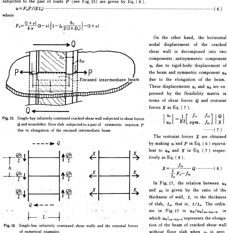
shear cracks occur inthe wall pan'el,the wall panelbecomesas an anisotropic plate,behaves the diagonalcompression fieldand dilates.,Themonolithic floorslabs togethet with theboundaryfrarneof the wall panel restrain the dilatationof thecrAcked'wall panel.Su6sequently, the role of the monolithic floorslab in restraining thedilatatien of the cracked shear wall isdiscussedbasedon axial force and deformation of intermediatebeam ofsingle-bay infinitely.continuedfrained sheqr wall.. The floor slab is assumed to be an infinitelysbreading
plate.Thisplateis a homogeneous one with thickness t.and is assumed tohaveplain stress. Thedilatingforces
due
toelongation of thebeams are assumed to be a pair of concentrated loadsP as illustratedinFig.15.Inthisfigure, therelativedisplacemepts
dueto a pair of symmetri.c loadsP cenfgrm tothe elongatien ofbgams
duetodilatatiQnof thecracked shear wall subjected toconstant'shear forcesQ
and restraint forcesX simultaneousiy. The restraintforcesX areequal tothepairof concentrated loadsP
(see
Figs.15 and 16).The horizontaldisplacementsu at pointssubjected tothe pairof loadsP
(see
Fig.15>afe given by Eq,(6).U=EsPl(Ets)m''-"'''"'H''H''H'':''''''"''"''""'H''H''"''H''''''H'''''''"''"'''''''''''"''"''-''"''H''H-''<6)
where .
'
Jz,=(ii.")(3-u)(i-in2(llCD.)]-(i+") ・
/ .)
.'' - ' On the other
hand
the horiiontal-
Q
'' ' nodal displacem'ent ''o'f tAe crackedi/
ho,im:,:
ii
W. '#":,t' ,i,:g,;
g
.iyll/li,il/f,r
l
'i
d/,c.:
i//.i
pl,.i
el
".iim .due to the elongation of the beam.
, Thesedisplacements,u, and uE are
pressed by the flexibilitymatrix in
terms of shear forces
Q
and restraintt t
Q-
, , ,' 'fercesx as Eq,(,7).
. Fig'i5 SQi:.gdie
bi.a.Y.ifi.[:,
ltefiiY..C,O,nit2:"::bCJI.a.Ctk.eddt.Sh.epa.ri:'gifi
S#yb.je;t.etlt,eS,h.e.a.l,f.O.rCepS1
l
uU,i
l
=::
St[
s
Sli'.
ll]l
lll
due toeiongation of the,encased intermedia!e beam
. .' '
The restraint f6rcesx alL"1'L(ta7iled /t ttt / /t tt ---- ・-)
e
T$hJ
tSh
h=Qth
",
,l`・Slihe,hl'
1・Slfh
Q<--・'
,f ./y .. ',' Vt'.L
z:-
.. Fig.16 Single-bayinfinitelycontinuedof numerical eitamples -110-'' '''' x・-xe
x,
.e' '' ' ' ' .i, 'Ttli},
l.tt・IS
'shear walls and the external forces
bymaking u 'and P inEq.
{
6)
lentto'u.' and X in'Eq.
(7)
' ' ' tively as Eq,
(
8),
' /t /t' X!.{ '
li:;th
9"-'""--(8)
In,Fig.'17,・the relat'ion 'betweenu,
and ", is given by'the ratio,of the
thicknes$ of wall, t, to the thickness
'ofslab, t.,thatis,tlt..The
ordin-i
ate in Fig.17 is 'ufilunl.iots=e,in
whicfi uu1..e,teLe'repTesents the
tion of thebeam of cracked shear wall
Architectural Institute of Japan
NII-Electronic Library Service
ArchitecturalInstitute of Japan un"i
i?e::
1.0 e.go,u O.7 O.6o.se.4 e.3 e.2O.1 o .---L.>Qzahthlz
QhTLltt t"tsft-1-ll
±Thlcknessefwell ts:Th[cknessofslab -10,vgt,Ps-e.ISI ttsm 3 O.5o.1 fo 'o.z os o.s o.e 1.o - ve
'
UI
Fig.17 Elongationratios ..lv..o of each interrnediate
' b'eam te'O
Fig.17suggests thatthefloorslab can not perfectly
restrain the di14tationof the shear cracked wall panel.
Ontheother hand,the relation betweenaxial foreeN,at theend of the beamof cracked shear wall and ", is
' . e o,2 os o.6 o.s 1.o
shown byparameter tlt.inFig.18.Itis observed that - i,t
the axial tension at theend of thebeamisdecreaSedbY Fig.
Is The ratio of axial force
lvh
to shearing forceQat the the restraint dueto thefloorslab. Consideringthese end of each intermediatebeamfacts,itcan bededucedthatthe sheai failurecan hardly
occur at the end of the beam of shear wall with floor.slab.
6.Conclusions
1) Theearthquake lateralloadsdistributedthTough the floorslabs are treated as concentrated loadson thenodal pointsatfourcorners of uncracked shear walls. Inthiscase, iftheaxi'al stiffness of thebeams isassumed tQberigid, the approximate solutions pertainingtothe nodal displacementsof the shear walls subjected toearthquake lateral
leadscan beobtained with accuracy. Thisresuit isuseful intheformulationof the nodal stiffness matrix of the shear
wall, .
'
2) When the diagonalshear cracks occu: inthewall panel,thewall paneldilatesand theaxial tensions yieldsin
theboundaryfrarneof the wall panel,Howevertheaxial tensionatthe end of beam doesnot become largeifthe
restraint action of monolithic floorslabs isexpected. References
1} Tomii,M., Hiraishi,H.,
"Elastic Analysis
of Framed Shear Walls byConsideringShearingDeformationof t,heBeamsand
Columnsof Their Bonndary Frames, Part I, ll, M", Trans.of AIJNo.273,Nov. 1978,pp.25-31,No.274,Dec. 1978, pp,75-85, No.275, Jan. 1979,pp.45-53,
2} Tomii,M..Yamakawa, T.,"Relations betweentheNodalForces
and theNodatDisplacementen theBounda[yFrarnes of
RectangularElastic Framed ShearWalls,PaTtV", TTans,of AIJ, No.241,Mar. 1976, pp.79-89.
3.)Tomii,M., Sueoka,T., Hiraishi,H.,
"Elastic Analysis
of Framed ShearWalls byAssuming Their InfMed Panet Watls to be 45-Degree Orthotropic PLates, PartI", Trans.of AIJ,No.280,Jun.1979, pp.101-109.
4) Tomii,M.,Hiiaishi,H.,"Elastic Analysis
of FramedShearWalls byAssuming Their InfilledPaneL WaLls tobe4s-Degree
OrthotropicPlates,Partil",Trans.of AIJ. No.284,Oct.1979,pp.51-60.
5) Toinli.M,. Esaki,F,, Funamoto,K., "Mechanical Behavior
of Two-Story or Two-Bay Duplex Framed ShearWalls
Having Shear Cracked Panel Walls",TTans.of JCI,Vol.4,1982, pp.313-324.
-111--"-"--Q
S"rhgh=t
e.3 O.25 O.2 O.IS O.1 glt gfgim
ieJ-i'-t:Thlcknessefwe]t ts:ThieknessofstabkS.lo,v.t.ps=o.2s:
3 05 1 (Temsien)o es o, Cemptession)-o. -e.1 C.5 e.1' . NII-Electronic MbraryArchitectural Institute of Japan
NII-Electronic Library Service
Arohiteotural エnstitute of Japan
【論 文1 UDC :69.022 :699.841 :69.025.22 :550.344 日本建築 学 会 構 造 系 論 文 報 告 集 第 377号 ・昭 和 62 年 7 月
地
震荷
重
を受
け る耐
震
壁の力学 挙 動
に及 ぼ
す
床
ス ラブ
の影 響
に関 す
る解 析 的研 究
(梗 概)
正 会 員 正 会 員 正 会 員 富 山 井 川 宮 政 ・英 哲. 雄* * 利 治* 整 1.序 鉄 筋コ ン ク リート ラーメン構造に多 用さ れ て いる耐震 壁は,床スラ ブ と一体に なっ て い,るの で, 床ス ラブが 地 震 荷 重 を受け る耐 震 壁の 力学 挙 動に及ぼす影響 を 検 討 す る ことは,耐 震設計 上必要な研 究 課 題の一つ と考え ら れ る。 床ス ラブは地 震 時の水 平 荷 重 を 耐 震 壁の側ばり に分 布 荷 重 として作 用さ せ,か つ 床ス ラブと一体になっ た 側 ばり の軸剛性や曲げ 剛性などを増 大さ せ る。そこで, 壁 板にせん 断ひび割れ が発生す る前の耐 震 壁の層 閲 変 形 角 に及ぼす床ス ラ ブの影 響に関して,水 平 荷 重の作用 形 式 と側ば り の剛性 評 価の観点か ら耐震 壁の フ.一リエ 級 数解 1)を利 用 し て検 討す る 。 こ の検 討 結 果 をふ まえて,マ ト リッ ク ス変 位 法に よ る有壁ラーメ ン の弾 性 解 析に用い る 耐 震 壁の節 点剛 性マ ト リッ クス2〕に, 床 ス ラブの影響を 考 慮し た数 値計 算例を示す。 一方,せ ん断ひび割れ が 壁板に発 生すると, 異 方 性 化 し た壁 板は圧 力場 を 形 成 し,床ス ラブは付 帯ラーメン と ともにその壁 板の広が り を拘 束す る。 こ の ように,せ ん 断ひび割れ後の耐 震 壁は複雑な力 学 的 挙 動を する。せ ん 断ひび割れ後の単 独や 2連耐 震壁の壁 板を, 4S°直 交 異 方 性 弾 性 板 と仮 定し たこれ ら の弾性 解 析が富 井らに よっ て発 表さ れ た3ト5 》。 本 論で は,富井ら が発 表し た 45°直 交異 方 性 弾 性 板のエ ア リーの 応 力関数3 )を用い て, せ ん 断ひび割れが 生 ずる均等無 限 連 続 耐 震 壁の弾性 解 析 を行 う。 次いで,こ の耐 震 壁に床スラブが取り付い た場 合の 付帯ラーメ ン の応 力や変形に関 して床ス ラブ が及ぼす力 学 的 影 響 を明らか にす る。 2.ひび 割 れが発 生 してい ない 耐 震 壁の層 間 変 形 角に ,及 ぼす床スラブの影 響 床ス ラ ブ が耐 震壁の層 間 変 形 角に及 ぼ す影響 を明ら か にするた めに, ひび 割れ が発生 して いない 単 独お よび無 本研究を日本建 築学会 大会学 術 講 演 梗概 集 昭 和57年10月, お よび 日本建築 学 会 中 国 ・九州 支 部 研 究 報 告 第6号昭和59年3 月に発 表し た。 摩 九 州 大 学 教 授 ・工博 韓 九 州 大 学 助手 ・工 修 tl* (株 〉日建 設 計 ・工 修 (昭 和 61 年 12月10 目原 稿 受理} 限 連ス パ ン 1層 耐 震 壁の層 間 変 形 角 を,次の 4’つ の場合 につ い て比較 検 討す る。 ’ 1 .i
:耐 震 壁の側ば りの材 軸 上に水 平 力 を 等 分 布 荷 重と し て作 用さ せ る。ii
:耐 震 壁の節点に水 平 力を集 中 荷 重とし て作 用させ る。iii
:耐 震 壁の側 ばり の曲げ お よ び せ ん断 剛 性 をそ のま まに し, 側ば りの軸剛性の み を無 限 大にする。iv
:耐 震 壁の側ば りの曲げ お よ び せ ん断 剛 性 を2お「よ び5倍に し,側ば りの軸剛性を 無限大に す る。 層 間 変 形 角の数 値 計 算は耐 震 壁の 5種 類の形状につ い て行 う。表一2よ りii
の場合にお け る柱の 部 材 角は,耐 震 壁の形 状によっ て は iの場合のそ れ よ りもか な り大き く な る。し たがっ て, 柱の実際の部材 角はiiの場 合の解 を使う と過 大 評 価さ れ る。iiの場 合にお け る柱の部 材 角 とス パ ン中 央 位置に お け る層 間変形角の相異は,耐 震 壁 の ス パ ンが大き く, 側 ばりの軸剛性が小さ く な るほ ど顕 著に な る。し か しなが ら, 1の場 合の 層 間 変 形 角は耐 震 壁 全 体にわ たっ て ほとんど一様で あ り, かつ これ ら の値 は1ii
の場 合の層 間 変 形 角1に ほぼ等しい 。 . 床ス ラブに よ る側ばり の 曲 げおよ びせ ん断 剛 性の増大 が耐 震 壁の層 間 変 形 角に及ぼす影 響 をみ る た め に, iiiの 場合の層 間変形 角に対 するiv
の場 合の層 間変形角の比 を 表一3に示す。表一3に よれ ば, 側ば りの曲げ お よびせ ん断 剛性の増 大が,耐 震 壁の層 間 変 形 角に及 ぼ す影響は 一般に小さい。し た がっ て,壁 板に せん断ひび割れ が発 生 し て いない耐 震 壁に床ス ラブか ら 分布して作用す る地 震 時の水 平 荷 重を,節 点 水 平 荷 重 として取り扱う場 合に は,側 ばりの軸剛性を無 限 大と仮 定すること ができる こ とを示してい る。こ の と き は,耐震 壁の節 点 外 力と節 点 変 位の関 係で ある節 点 剛性マ トリッ クス を定式 化す る上 で有 用である。 「 ’ 3.床ス ラブの影響を 考 慮 し た単 独 耐 震 壁の基 本節点 剛性マ.ト リ、ッ クスに関 す る 数 値計算 例 2項で の検 討 結 果,耐 震 壁の基 本 節 点剛性マ ト リック ス K* を定 式化 す る 場合に は,側ばり の軸 剛 性を無 限 大 と仮 定する こ と がで きる。各 基 本型ごとの KI が解 析 解 一一112
一 N工 工一Eleotronio LibraryArchitectural Institute of Japan
NII-Electronic Library Service
Arohiteotural エnstitute of Japan
と して 求め られ る と, 一般 的な耐 震 壁の節 点 剛 性マ ト リッ クス K が, 変 換マ トリックス を利 用 し て容 易に誘 導さ れ るm。 壁板の中心 を通る縦軸に関し,対称な基 本 成 分か ら な る 且型の Kt お よ びW 型の K髭は, 剛棒を側ば り両 端の 節 点 間に かけわ たすことに よっ て, 剛 床が取 り付いた場 合の近 似 解が求め られ る。