Design and Heat-dissipation Characteristics of a Novel Spectrally Selective Thermal-radiation Material
4
0
0
全文
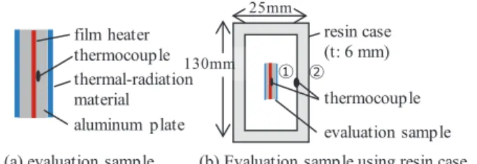
(2) Transactions of The Japan Institute of Electronics Packaging. Vol. 14, 2021. resin. 25mm. resin layer metallic-particle-array layer in resin heating element. Fig. 3. metallic spherical particles. Structure of coating-type SSTRM.. Fig. 4. versatility because a fine periodic structure is formed on. ple.. several problems. For example, this technology requires a. A. Spectral selectivity of C-SSTRM. Fig. 5. (C-SSTRM) with a high degree of freedom in shape at a low cost and (ii) verify its heat-dissipation characteristic.. occurs in the vicinity between the metallic particles.[4]. metallic-particle-array layer in resin. Cross-sectional image of C-SSTRM.. 1.00. absorption (a.u.). It has been reported that the localized plasmon resonance. resin layer. 80µm. pose of this study is to (i) develop a coating-type SSTRM. The basic structure of the C-SSTRM is shown in Fig. 3.. evaluation sample. IV. RESULTS. form fine structures in small areas. Accordingly, the pur-. Structuire of C-SSTRM. thermocouple. Cross-section view of heat dissipation evaluation sam-. semiconductor manufacturing process, and it can only. 2.. ① ②. (a) evaluation sample (b) Evaluation sample using resin case Figure 4. Cross-section view of heat dissipation evaluation sample. plasmon resonance. This technology is inferior in terms of the surface of a thin metal film. However, SSTRM faces. resin case (t: 6 mm). film heater thermocouple 130mm thermal-radiation material aluminum plate. 0.80 0.60 0.40 0.00. C-SSTRM was therefore investigated by using localized. C-SST RM resin. 0.20 2. 4. plasmon resonance in the vicinity between the metallic Fig. 6. particles. It is composed of the metallic spherical particles. 6. 8. 10. wavelength (µm). 12. 14. Absorption spectra.. arrayed on the bottom of a resin layer, which is the surface of a heating element. Heat energy transmitted from the. sides in shown in Fig. 4(a). The heating element consists. heating-element surface to the metallic-particle-array layer. of a film heater sandwiched between aluminum plates. A. is converted into light energy. Localized plasmon reso-. thermocouple is placed between the film heater and the. nance is generated from the metallic-particle-array layer. aluminum plate (size: 20×20 mm; thickness: 1 mm). The. and emitted as infrared light. It is known that the emissiv-. evaluation method using a resin case is shown in Fig. 4(b).. ity (absorption ratio) increases at the wavelength at which. The evaluation sample was installed so as not to contact. the localized plasmon resonance becomes strong. As. the case. The surface temperature of the sample was mea-. shown in Fig. 2, if the emissivity of the metallic-particle-. sured 60 minutes after applying a constant voltage to the. array layer increases in the low-wavelength region (blue. heater. The evaluation environment was kept at ambient. portion in Fig. 2), emitted infrared light is transmitted. temperature of 25°C under natural convection. Tempera-. through the resin layer and heat dissipation of the resin. tures were measured at the surfaces of the heater and the. package is increased. Consequently, heat dissipation from. resin case.. the heating element is improved. 3.. Experimental. 4.. Results. A.. Spectral selectivity of C-SSTRM. The solution for C-SSTRM was prepared by mixing. A cross-sectional image of C-SSTRM (made of metallic. metallic particles, resin, and solvent. After the coating. particles with average size of 1.6 μm) is shown in Fig. 5.. material was applied, the metallic particles (having a spe-. The metallic-particle-array layer was formed at the bottom. cific gravity higher than that of the resin) were spontane-. of the resin layer.. ously settled in the resin to form the metallic-particle-array layer.. Absorption spectra of C-SSTRM and the resin are shown in Fig. 6 that was measured by specular reflectance FTIR –. The evaluation sample for verifying the heat-dissipation. microscopy using a gold mirror as a standard reference. In. characteristics of C-SSTRM is shown in Fig. 4. The heating. the wavelength region of less than 5.3 μm, the absorption. element with the thermal-radiation material coated on both. spectrum of the resin was low. On the contrary, the absorp-. E20-006-2.
(3) Surface temperature (°C). Ito et al.: Spectrally Selective Thermal-radiation Coating Using Metal Particle (3/4). 130 110. heating element when applying C-SSTRM and the conven-. 122.4°C 102.5°C 100.6°C. without coating conventional material C-SST RM. 90 70 50. 44.7 °C. 48.7 °C. 41.2 °C. 30. heating element resin case Figure 7. Heat-dissipation characteristics minutes Fig. 7 Heat-dissipation characteristics in in 6060 minutes.. tional material is considered to be due to the surface temperature of the resin case. The surface temperature of the resin case with C-SSTRM was 3.5°C lower than that without the thermalradiation material, and 7.5°C lower than with the conventional material. The reason that the surface temperature of the resin case without the thermal-radiation material is lower than with the conventional material is following. It is. tion spectrum of C-SSTRM in the same wavelength range. difficult to emit heat energy from the heat element. was higher than that of the resin. The difference between. because emissivity of the evaluation sample without the. these spectra is due to the localized plasmon resonance. thermal-radiation material is low. As a result, the heat. excited in the metallic-particle-array layer. The absorption. energy was hardly absorbed in the resin case, and the sur-. in the wavelength region of 2 to 6 μm is important for heat. face temperature of the resin case was lower than that. dissipation by thermal radiation in the temperature range. when the thermal-radiation material was used. The differ-. of the electronics devices. This is because that as the tem-. ence in the surface temperature of the resin case when. perature of the electronics devices rise, the radiant inten-. applying C-SSTRM and the conventional material is con-. sity of the wavelength region between 2 to 6 μm become. sidered as follows. The conventional material emits infra-. stronger than other the wavelength region, by Planck’s. red light at the wavelength where the resin has a large. law.[5] This result infers that infrared light from the metal-. infrared absorption. Therefore, infrared light is emitted. lic-particle-array layer of C-SSTRM can effectively transmit. from the conventional material is absorbed by the resin. heat through the resin.. case. On the other hand, as shown in Fig. 6, C-SSTRM. B. Heat-dissipation characteristics of C-SSTRM. emits infrared light that include the wavelength region in. In general, the heating element is packed into the pack-. which infrared absorption of the resin is low. That is,. age. The heat-dissipation characteristics of C-SSTRM were. C-SSTRM emits infrared light that passes through the. evaluated by using a sealed resin case.. resin case. For that reason, rise in surface temperature of. The evaluation samples consisted of an aluminum plate. the resin case can be suppressed by applying C-SSTRM; in. with the conventional thermal-radiation material, with. other words, it is suggested that the heat dissipation of the. C-SSTRM, or without the thermal-radiation material. The. case was improved by C-SSTRM.. conventional thermal-radiation material used this time is consisted of dispersed ceramic particles. Thickness of each material was approximately 100 μm.. 5. Conclusion A coating-type selective thermal-radiation material,. Heat-dissipation characteristics in the sealed resin case. C-SSTRM, which emits infrared light through a resin layer,. are shown in Fig. 7. The temperature of the heating ele-. was developed, and its heat-dissipation characteristic was. ment without the thermal-radiation material was 122.4°C,. verified. C-SSTRM is composed of densely arranged metal-. that with the conventional material was 102.5°C, and that. lic particles, with a specific particle size, fixed to the resin. with the C-SSTRM was 100.6°C. The temperature of the. layer. As part of this structure, C-SSTRM provides efficient. resin case without the thermal-radiation material was. spectral emission. In particular, the effect of C-SSTRM on. 44.7°C, that with the conventional material was 48.7°C and. spectral emission is remarkable in the case C-SSTRM is. that with the C-SSTRM was 41.2°C.. applied to a sealed case.. Comparing the three samples reveals that coating the aluminum plate with C-SSTRM results in the lowest sur-. References. face temperatures of the heating element and the resin. [1] Y. Sha, Y. Jhuo, K. Chen, and S. Wang, “Thermal Radi-. case. This result thus confirms that heat dissipation is. ation Material for Electronic Devices Applocations,”. improved by applying C-SSTRM.. Internatinal Microsystems, Packaging, Assembly and. The surface temperature of the heating element with. Circuits Technology Confrence, 8th., pp. 74–77, 2013.. C-SSTRM was 1.9°C lower than that with the conventional. [2] T. Makino and H. Wakabayashi, “Experimental Verifi-. material. The difference in the surface temperature of the. cation of Kirchhoff’s Thermal Radiation Law on Sur-. E20-006-3.
(4) Transactions of The Japan Institute of Electronics Packaging Vol. 14, 2021. faces With Emittance Spectra Characterized by Opti-. [4] H. Wang, J. Kundu, and N. J. Halas, “Plasmonic. cal Interference Phenomena,” Internatinal Heat. Nanoshell Arrays Combine Surface-Enhanced Vibra-. Transfer Conference, pp. 899–905, Mar. 2011.. tion Spectroscopies on a Single Substrate,” Angew.. [3] S. Tsuda, M. Shimizu, F. Iguchi, and H. Yugami, “Thermal Management Technique Using Control of. Chem. Int. Ed., Vol. 46, No. 47, pp. 9040–9044, Dec. 2007.. Thermal Radiation Spectrum for Encapsulated Elec-. [5] G. Kramm and N. Molders, “Plank’s blackbody radia-. tronic Devices,” IEEE Trans. On Components, Pack-. tion law: Presentation in different domains and deter-. aging and Manufacturing Technol., Vol. 5, No. 7, pp.. mination of the related constants,” Journal of the Cal-. 971–979, Jul. 2015.. cutta Mathermatical Society, Nov. 2009.. Maki Ito received the M.E. degree from. Takanobu Kobayashi received the B.E.,. Tokyo University, Tokyo, Japan in 2012. She. M.E., and Dr.E. degrees from Gunma Uni-. joined Hitachi, Ltd. In 2012, and has been. versity, Japan, in 1993, 1995, 2000, respec-. working on studies of thermal dissipation. tively. From 1999 to 2000, he was with. materials. She received in 2015 a Best Paper. COLCOAT Co., Ltd, Saitama, Japan. Since. Award from the Japan Institute of Electron-. 2001, he has been with Research & Develop-. ics Packaging. Takashi Ando received the B.E., M.E., and Dr.E. degrees from Hosei University, Tokyo, Japan, in 1991, 1993, 2003, respectively. From 1993 to 1998, he was with TDK Corporation, Chiba, Japan. Since 2003, he has been. ment Group, Hitachi Chemical Co. Ltd. (current company name is Showa Denko Materials Co., Ltd.), Ibaraki. His research is the design of adhesives based on polymer properties. The product he was involved in won the award of Advanced Display of the year (Par ts/Material depar tment), in 14 th FINETECH JAPAN 2004.. with Research & Development Group,. Yoshitaka Takezawa received the B.E.,. Hitachi, Ltd., Ibaraki. His research interests. M.E., and Ph. D. degree in applied chemis-. include electromagnetic wave propagation problem and semicon-. try from Keio University, Tokyo, Japan, in. ductor packaging technologies. He received an IEEE AP-S Japan. 1985, 1987, and 1993 respectively. He joined. Chapter Young Engineer Award, in 2002.. Hitachi, Ltd., Japan, in 1987 and had been engaged in insulating polymer materials.. Naoki Maruyama received his MEng degree from Tohoku University, Sendai, Japan in 2004. He joined Hitachi Chemical Co. Ltd. (current company name is Showa Denko Materials Co., Ltd.) in 2004. He has been working on the development of display materials, self-organized epoxy for high toughness materials, thermal dissipation and insulation materials.. E20-006-4. Since 2008, he has been working for Hitachi Chemical Co., Ltd. (current company name is Showa Denko Materials, Co. Ltd.), Japan, and is concerned with high-thermalconductive mesogenic epoxy resins and thermal control materials. He was awarded in 1998 from IEE of Japan for his outstanding research paper..
(5)
図


関連したドキュメント
The method proposed in this article solves this problem by breaking the integration procedure into two steps, the time-stepping using the invariant numerical scheme with an
The reflection method together with the solution obtained for the whole space is applied to a semispace problem with a plane dis- tribution of heat sources located inside the
In this work, we have theoretically studied the effect of thermal radiation and thermal diffusion on unsteady MHD free convection heat and mass transfer flow of an
The reflection method together with the solution obtained for the whole space is applied to a semispace problem with a plane dis- tribution of heat sources located inside the
16 examined the simultaneous effects of variable viscosity, variable thermal conductivity, and Ohmic heating on the fluid flow and heat transfer past a continuously moving porous
So, the aim of this study is to analyze, numerically, the combined effect of thermal radiation and viscous dissipation on steady MHD flow and heat transfer of an upper-convected
In particular, we show that the q-heat polynomials and the q-associated functions are closely related to the discrete q-Hermite I polynomials and the discrete q-Hermite II
It has been shown that the fluid is accelerated, that is, velocity u is increased with an increasing values of time t, chemical reaction parameter δ, Prandtl number Pr,
