博士論文
Stress and quality engineering of GaN growth
on Si with in-situ wafer curvature analysis
(
In situウエハ曲率解析によるシリコン上窒化ガリウム
成長における応力・結晶品位の制御)
Stress and quality engineering of GaN growth on Si
with in-situ wafer curvature analysis
In situウエハ曲率解析によるシリコン上窒化ガリウム成
長における応力・結晶品位の制御
A dissertation submitted to the Graduate School of Engineering
The University of Tokyo
In partial fulfillment of the requirements for the degree of
Doctor of Philosophy
劉 才
Cai Liu
Under the supervision of
Professor Dr. Yoshiaki Nakano
Acknowledgements
There is an old Chinese saying that “Thirty years of age when a man should stand on his own feet.” Steve Jobs said “… the only way to do great work is to love what you do. If you haven't found it yet, keep looking.” Everyone was born with an innate mission to experience or complete this life. Pursing a Ph. D. degree is not only a good training to be an independent and qualified scientist or engineer with some new contribution to the knowledge of human beings, but more importantly, at least for me, it is also a journey to find the innate mission of mine. Even with deep paining and struggling, it was really a good journey to travel. I am so grateful to all the people I have met on this nice journey.
Firstly I have to convey my great appreciation and respect to Japanese people and government to support my study in Japan. I never imaged studying abroad if there is no such precious support. All people I met here are very warm and friendly, they are always happy to render help to others.
I would like to show my sincere gratitude to my advisor, Professor Yoshiaki Nakano, who gave me the chance to study in The University of Tokyo and supported my study here, and my co-advisor, Associate Professor Masakazu Sugiyama, who offered me the interesting research topic and much helpful advice from research to presentation with great patience. I have learned very much from their teachings and I could not have completed my dissertation without their teachings and support.
I also appreciate the help and critical comments from Professor Katsushi Fujii, Professor Yoshitaka Okada and Associate Professor Takuo Tanemura to point out some basic but critical problems in my research.
Special thanks to the cooperating company to support my work.
Besides, I could not have finished my work without great friendly help from many people, including Assistant Professor Hassanet Sodabanlu, Assistant Professor Yunpeng Wang, Assistant Professor Kentarou Watanabe, Assistant Professor Masanori Kubota and Assistant Professor Akio Higo. The help from some other people also enabled me to work smoothly, including Mr. Hongbo Wang, Mr. Manish Matthew, Ms. Kayo Koike, Mr. Akihiro Nakamura and all members of Nakano-Sugiyama-Tanemura Laboratory.
I should also give my most sincere thanks to the doctors and nurses in The University of Tokyo Hospital who offered me the best medical treatment and help me to recover from the illness quickly. They always make people warm like the sunshine in winter. Another group of people who I have to show my great appreciation to are my friends who were also chasing their dreams here for that they looked after me very carefully when I could not move on the bed in the hospital.
Last but not least, I would like to say “thank you” to convey my deepest love and gratitude to my parents and my wife and other families. They are always my endless source of power to go through any happiness and difficulty in the life. In the end, there are some
special words to my beloved wife, thank you for coming to my life, lighting it and enlightening me.
Cai Liu
Abstract of Dissertation
Stress and quality engineering of GaN growth on Si with in-situ wafer curvature
analysis
(In situ ウエハ曲率解析によるシリコン上窒化ガリウム成長における応力・結晶品 位の制御)
劉 才
This work has been devoted to the clarification of basic growth mechanism of GaN on Si employing AlN buffer layer and AlN interlayers, including the stress behavior of both GaN and AlN layers as well as the influence of AlN buffer and interlayers on the quality of GaN, based on the in-situ curvature monitoring and other characterizations. The unique points of this work are as follows.
(1) A model of ideal AlN interlayer to induce compressive stress in GaN layers has been proposed, based on systematic in-situ curvature monitoring and morphology observations. This model has pointed out the key features that ideal AlN interlayer should possess, which are small lattice constant close to neutral AlN and high-quality coherent upper interface of it. In most of the cases small lattice constant of the interlayer demands relaxed lower interface of it.
(2) A routine of arbitrary wafer bow design has been discovered and a program to realize it has been produced. Prior to applying this routine, the strain and stress states in every individual AlN and GaN layer under certain growth conditions should have been known. After setting the mechanical properties of AlN and GaN layers, arbitrary wafer bow design is available. This routine was put forward for the first time.
(3) Prototypes of innovative AlN interlayers have been invented and tested, following the model of ideal AlN interlayer. They are one-step pulse-injection method AlN IL, two-step low-temperature/pulse-injection AlN IL and two-two-step low-temperature/high-temperature AlN IL. All the interlayers employed in previous studies were one-step conventional AlN. These new AlN ILs grown by special methods or with special structure have proved the reliability of the ideal AlN IL model and are induced larger compressive strain in GaN than normal conventional AlN ILs.
The work flow started with demonstration of successful GaN growth on Si (111) substrate by clearing all obstacles. Following the sample structure, conventional AlN buffer layer and AlN interlayer were investigated successively, including their growth conditions, stress introduction in overlying GaN and influence on GaN quality. Then based on the in-situ curvature monitoring data, strain states in every layer were analyzed and model of ideal AlN interlayer and a routine of arbitrary bow design were proposed. In the end, three prototypes of innovative AlN interlayer were designed and tested.
The most important benefit of GaN-on-Si is cost reduction by using Si substrate and the advantages of combining nitrides and silicon. The basic difficulties of the growth of GaN on Si lie in the large lattice constant mismatch (~ 17%) and thermal expansion coefficient
mismatch (~ 54%) between them. This work aimed at understanding and clarifying the stress control mechanism and the roles of AlN buffer layer and AlN interlayers in the growth of GaN on Si.
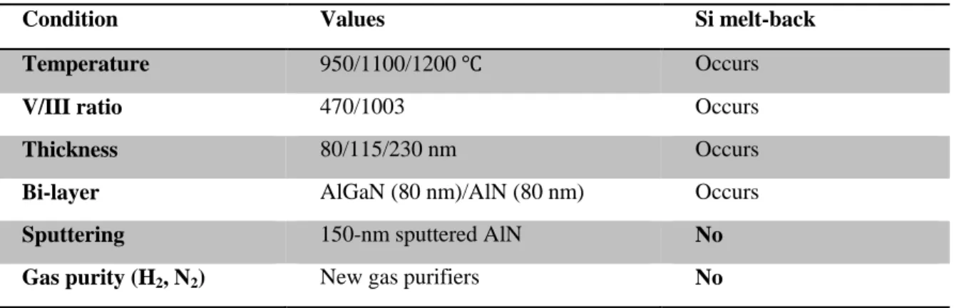
The most serious difficulties included Si melt-back, Si surface nitridation and the stability of growth environment inside the reactor. There were many factors to facilitate Si melt-back, such as the adsorption of H atoms and cleanliness of Si surface, Ga contamination on Si surface from the parts in the reactor prior to the growth of AlN buffer layer, and most importantly the quality of AlN buffer layer. Ga contamination can be eliminated by using clean liner tube and susceptor parts, or AlN coating of the inner of reactor. Nothing was working to stop Si melt-back if the AlN buffer quality was poor. Finally, after changing for new gas purifiers, AlN buffer quality was improved significantly and Si melt-back was eliminated. Nitridation of Si surface was avoided by pre-flowing TMAl source, 10 s under flow rate of 22 sccm. Proper TMAl pre-flow also improved the GaN quality substantially. The chemical environment inside the reactor should be kept to be constant to yield controllable growth. The most important point was deposited GaN or Ga should be covered since they may cause Ga contamination on Si surface. Therefore, AlN coating or AlN dummy growth should be performed prior to every growth of GaN on Si.
Curvature can be adjusted by tuning the quality of AlN buffer layer which determines the
stress in the 1st GaN, changing the growth conditions and the number of AlN interlayers, and
tuning the growth mode and thickness of the 1st GaN. AlN buffer layer is important for both
of the strain and quality of the 1st GaN. The AlN buffer with higher quality caused more
compressive strain in the 1st GaN. It was initially compressively strained. The strain transited
from being compressive to tensile as the thickness increased. However, the relaxation speed was depending on the growth conditions and quality of AlN buffer layer. The relaxation was very rapid and the critical thickness from being compressive strain to tensile was only several
hundreds of nanometers, if the AlN buffer quality was low, such as grown at 1000 ℃. This
was because of high-density defects in AlN buffer propagated into or caused more dislocations in overlying GaN and led to more rapid relaxation in GaN. The best AlN buffer
layer which induced most compressive strain was grown at 1250 ℃, under V/III ratio of 3005
and with thickness of 110 nm. Growth conditions of conventional one-step AlN interlayers were studied intensively, including thickness from 4.5 nm to 45 nm, growth temperature from
600 ℃ to 1200 ℃ and V/III ratio from 115 to 9015. Optimized AlN interlayer which induced
the most compressive strain in GaN was grown at 900 ℃, under V/III ratio of 1503 and with
thickness of 9 nm. If it was too thin, it consisted of neighboring separated grain domains. In too thick AlN IL, cracking occurred. Both lost the capability of inducing compressive strain
in GaN. If the growth temperature was too low like 600 ℃, although with smaller lattice
constant, since it was amorphous and not coalesced, the GaN on it relaxed rapidly. In
high-temperature (> 1000 ℃) ones, Ga diffusion into the interlayer happened, formed AlGaN with
lattice constant more close to GaN and then small compressive strain in GaN. V/III has minimal influence on the performance of AlN IL if it was in the range from 500 to 1500. A model of ideal AlN IL was proposed based on the observations, with relaxed incoherent lower interface and high-quality coherent upper interface.
Based on the review of stress generation mechanisms in heterostructure, methodology of analysis was built. The tensile strain of AlN buffer layer ranged from 0.25% to 0.5% while the ideal misfit strain of AlN on Si is about 23.2%, which indicates that AlN buffer on Si is almost completely relaxed. The tensile strain decreases as the growth temperature is elevated. Such relaxation is favorable to stressing overlying GaN more compressively. Depending on the growth conditions of AlN buffer layer, the relaxation speed from compressive (~ -0.45%) to tensile strain (~ 0.05%) differs in the 1st GaN. The thickness of neutral point is only about
600 nm if the quality of AlN buffer is poor such as grown at 1100 ℃. On the best AlN buffer,
compressive strain through the large thickness of 1.75 um can be maintained. In spite of smaller lattice constant between AlN and GaN, tensile strain in AlN interlayers is much higher than that in AlN buffer, which ranges from 1.45% to 1.9%. The relaxation was in the range from 22% to 42%, which is about only one third of that in AlN buffer. These results show that the crystal quality of AlN interlayers is better than that of AlN buffer layer. The
largest compressive strain in GaN layers is about 0.45% on AlN interlayer grown at 900 ℃
and with thickness of 9 nm, which is the same of the initial value of the 1st GaN. This leads to compressive stress of about 2 GPa in GaN and is 2~3 times of that in previous publications. Curvature due to thermal stress was also calculated. Based on the strain and stress states in every individual stage, the curvature curve can be recovered and the final curvature and wafer bow can be predicted, using the arbitrary bow design program. The size of Si wafer which the curvature and wafer bow is easiest to be controlled is 6 inch, 150 mm.
Quality elevation of AlN buffer layer and 3D growth mode are the most effective methods
to improve the quality of GaN. The same with compressive stress introduction in the 1st GaN,
it also demands high-quality AlN buffer layer to produce high-quality GaN, since the defects in the buffer can propagate into overlying GaN and they can also act as defect sources to generate new dislocations in GaN. Using conventional AlN, higher quality is achieved at
higher temperature, 1250 ℃ in this work, under mediate V/III ratio of 3005. By alternating
growth mode from 2D to 3D, the FWHM of XRD rocking curves of the plane (10-10) reduced from 820 arcsec to 570 arcsec while that of (0002) plane keeps almost constant.
Thick AlN interlayer (≥ 22 nm) is favorable to the reduction of dislocations in GaN, but not
for stress inducing. Since it doesn’t coalesce completely, thin AlN IL (< 13 nm) increase the dislocation density in GaN by introducing new defects at the grain domain boundaries. Blue LEDs has been demonstrated.
Concepts of innovative prototypes of AlN interlayers were designed and tested, including one-step pulse-injection method AlN IL and two-step IL consists of lower low-temperature AlN and upper pulse-injection AlN or high-temperature AlN. In the structure of LT/HT-AlN,
the growth temperature of HT-AlN higher is better such as 1200 ℃, with optimal thickness
around 6 nm. They confirmed the solidity of ideal AlN model and showed the same performance of the best conventional AlN. For that the growth conditions of them were not optimized, more compressive strain in overlying GaN on them can be expected.
Content
1 Introduction ... 1
1.1 Why GaN-on-Si? ... 1
1.2 Basic difficulties ... 4
1.2.1 Lattice constant mismatch ... 5
1.2.2 Thermal expansion coefficient mismatch ... 7
1.3 Status ... 8
1.4 Motivation and targets ... 11
1.5 Synopsis of this dissertation ... 12
2 Procedure of successful GaN MOVPE on Si ... 17
2.1 Basic procedure of GaN MOVPE on Si ... 17
2.1.1 Metal-organic vapor phase epitaxy ... 17
2.1.2 In-situ curvature monitor ... 19
2.1.3 Scanning electron microscope ... 20
2.1.4 X-ray diffraction ... 21
2.2 Si melt-back ... 22
2.2.1 What Si melt-back is ... 22
2.2.2 Gallium deposition on Si wafer surface ... 23
2.2.3 Si Surface cleaning and hydrogen atom adsorption ... 25
2.2.4 Quality of AlN buffer layer ... 27
2.3 TMAl pre-flowing ... 29
2.4 AlN dummy coating ... 31
2.5 Conclusion - standard procedure ... 35
3 Experimental observation of stress control by conventional AlN ... 39
3.1 Introduction ... 39
3.1.1 Curvature transition curve ... 39
3.1.2 Strategies to achieve zero bow ... 41
3.1.3 Stress introduction and strain relaxation mechanisms ... 42
3.2 Stress introduction by AlN buffer layer ... 47
3.2.1 Temperature effect ... 48
3.2.2 V/III ratio effect... 53
3.2.3 Thickness effect ... 56
3.3 Effects of AlN interlayers ... 58
3.3.1 Introduction ... 58
3.3.2 Thickness effect ... 63
3.3.3 Temperature effect ... 67
3.3.4 V/III effect ... 73
3.4 Curvature adjustment by GaN growth mode and thickness... 74
4 Theoretical analysis of stress and strain behavior ... 83
4.1 Stoney formula ... 83
4.2 Stress and its origins in heterostructure ... 86
4.2.1 Intrinsic stress and its origins ... 86
4.2.2 Stress contributions from the upper interface (or film/vacuum surface) ... 89
4.2.3 Extrinsic stress and thermal stress in elastic multilayer system ... 89
4.2.4 Analysis method in this study ... 91
4.2.5 Material parameters ... 94
4.3 Stress and strain in AlN buffer layer and overlying GaN ... 96
4.4 Stress and strain in AlN interlayers and overlying GaN ... 102
4.5 Plastic deformation of Si substrate ... 109
4.6 Arbitrary bow design and curvature simulation ... 111
4.7 Conclusion ... 114
5 Quality of GaN on conventional AlN ... 119
5.1 Introduction ... 119
5.2 Effects of AlN buffer layer on the quality of GaN ... 120
5.2.1 Effect of growth temperature of AlN buffer layer ... 121
5.2.2 Effect of V/III ratio of AlN buffer layer ... 125
5.2.3 Effect of AlN buffer layer thickness ... 127
5.3 Effect of AlN interlayers on GaN quality ... 128
5.4 High quality brought by 3D growth mode ... 135
5.5 LED on GaN-on-Si ... 137
5.6 Conclusion ... 138
6 Innovative AlN interlayers ... 143
6.1 Why innovative AlN interlayer?... 143
6.2 Pulse-injection AlN interlayer ... 144
6.3 Pulse-injection/Low-temperature two-step AlN interlayer... 146
6.4 High-temperature/Low-temperature two-step AlN interlayer ... 148
6.5 Conclusion ... 151
7 Conclusions... 153
Appendix A Program for predicting curvature and wafer bow ... 159
Appendix B Void formation and its effects ... 163
B.1 Introduction ... 163
B.2 Void formation by hydrogen etching ... 164
B.3 Factors in the formation of voids ... 166
B.4 Effects of voids on the property of GaN ... 167
B.5 Conclusion ... 170
Appendix C Suggestions on further research ... 173
1 Introduction
Motive force, basic growth problems and status for the research of GaN-on-Si will be given in this chapter. Based on it, the motivation and target of this work would be proposed. By enumerating the demand of modern society and material advantages of nitrides and silicon, the motive force for the field of GaN-on-Si was introduced in section 1.1. Basic growth difficulties were given in 1.2. Research status from both the industry and academic communities was reviewed in 1.3. In the end of this chapter, motivation and content of this work was outlined.
1.1 Why GaN-on-Si?
Information and energy are almost the hottest topics in our modern society. This is a time that human beings are producing data in one hour more than in centuries hundreds years ago. Be confronted with explosive data, traditional electronic devices based on silicon cannot satisfy the present huge demand for massive high speed data storage, transmission and processing, with high energy consumption. In order to elevate the processing speed and lower the unit energy consumption per bite, people are working hard to transmit and process information using photons as carrier rather than electrons. Compared with electrons, movement of photons can be much more speed and energy efficient. III-V materials are the best practical option for optical and photonic devices due to their fantastic optical and electric properties, but of limited material resource and high cost. However, due to the advantages of resource abundance, well-developed growth and processing technologies, large size silicon wafer is very cheap and large scale fabrication on it can be done readily. This might be the driving force for both academic and industry communities to make a great investment in the field of incorporating devices based on V-III materials with silicon, to make photonic devices and circuits more powerful, cheaper, energy efficient and more environment-friendly. Nitrides-on-silicon is one of the most important branches of it.
On the other hand, in 2013, fossil energy source still supported more than 90% of the
annual total energy consumption of the world [1]. Oil, natural gas and coal, which are the
fossil energy family, can only serve the human society for about 53 years, 55 years and 230 years respectively [2]. No much time left for people to explore new energy which can play the role of present fossil energy in the future. People are showing great expectation of producing electricity from sunlight. Photovoltaic technology is a very promising method to realize it. Both silicon and nitride are fantastic materials for the fabrication of solar cells and harvesting sunlight.
Specifically, both silicon and nitrides are of fantastic material properties.
Silicon is the cornerstone of modern society. With mediate band gap value of 1.11 eV at room temperature and easy growth and doping process, it has been applied for producing electronic chips and solar cells from 1960s. For the information industry, almost all electric chips and processors were made from it. For the field of solar electric power generation, solar cells based on silicon hold the largest market share. To satisfy the enormous material consumption, harsh crystal quality requirement for making electronic devices, and to lower the cost by large-scale production, low price and high quality single crystal silicon wafer with large size up to 18 inches is available now [3]. Price is the most important competitiveness of it. In addition to the most developed crystal growth technology, the process technology for silicon is also the most mature. This is why people are working hard to incorporate V-III devices on the basis of existing advantages of silicon. Also, for its high crystal quality, well-developed processing technologies and low cost, silicon-based solar cells held the
photovoltaic market share of about 90% in 2013[1].
III-nitride is a fantastic material family, represented by gallium nitride (GaN). They are of
direct energy band-gap (Eg) which ranges from 6.2 eV (aluminum nitride, AlN) to 0.7 eV eV
(indium nitride, InN). Such a direct and wide Eg range covers photon energy from deep
ultra-violet, solar spectrum and far ultra-red spectrum [4]. With mediate Eg of 3.4 eV and lattice
constant of 3.189 Å between AlN and InN, as well as relatively easier growth, GaN comes to
be the template material for the growth of other nitrides and devices made from them. AlN, InN and GaN of course, as well as their ternary compounds compose the active region of nitride devices. The direct band-gap makes it suitable for high electron mobility transistors
(HEMT) [5], with electron mobility (𝜇𝜇𝑒𝑒) of 900 cm2/V∙s for GaN. The very large band-gap
makes nitrides can meet the market demand of two big field, which other material cannot do. First is the market of blue and ultra-violet light emission diodes (LED) and laser [6], using the ternary compound like AlGaN and InGaN as active layers. The other one is the market of devices working under high power or high temperature, such as high power switches. Take
GaN as an example, thanks to its Eg of 3.4 eV, the breakdown field of the devices makes
from it could be as high as 3.3×10⁶ V/cm which is about 10 times of that of Si and gallium
arsenide (GaAs). The working temperature of them could be as high as 400 ~ 500 ℃. The
direct and large band gap, the large band-gap off between nitrides and some other outstanding properties lead them to be the most appropriate candidate for fabricating the very high frequency [7] all-optical switches and photon detectors by applying multi-quantum well (MQW) or super-lattice (SL) structures [8]. InGaN with band-gap from 3.4 eV to 0.7 eV is an ideal material for high efficiency solar cells because it can cover the entire solar spectrum, although currently it is still hard to tune the indium content and band-gap freely [9]. Benefited from such great band-gap tunability, amazingly, monolithic white LED has been achieved without applying phosphor powder [10]. At present, the most dominant product of nitride device market is semiconductor LED, which is called as the fourth generation of lighting technology and much more energy efficient.
However, even with such broad application prospects, the basic difficulty hinders the development of nitride devices is that it is not easy to grow high quality nitride films, especially AlN and InN, as well as their alloys with GaN. This often causes the performance of fabricated devices is much lower than theoretical prediction. Besides this, the cost is also
another critical factor to limit its development and application in the market. The lack of cheap and large size lattice matching substrate for the epitaxy of nitrides is one of the main causes for both of the growth difficulty as well as the high cost. GaN is the only substrate available for nitride homo-epitaxy with very high price and small size less than 4 inches of diameter. Among substrates for hetero-epitaxy, SiC and ZnO are of the smallest lattice constant mismatch of 3.3% and 2.1% respectively. Like GaN free-standing wafer, their price
is also very high and the size of them cannot be large. Currently, sapphire (Al2O3) is mostly
being used for GaN epitaxial growth. The cost of wafer can be reduced by 90% by increasing procedure scale which is limited by the size of sapphire wafer.
The initial motivation to grow nitrides on silicon was to reduce the cost of nitride devices. In order to reduce the cost of LEDs further substantially, GaN-on-Si composite substrate for the growth of LEDs and other devices has been proposed since a decade ago [12]. As shown in Table 1.2, as a substrate for the growth of nitrides, there are some distinctive advantages with silicon. As mentioned above, the most attractive superiority of silicon is low cost, large size and the best crystal quality, benefited from the relatively easy and most developed growth technology. The cost of silicon is only one fourth of that of sapphire (2 inches). From the industry it shows that the cost reduction for wafer can be as high as 75% from 2’’ sapphire to 200 mm silicon [13]. The large size of silicon wafer up to 12 ~ 18 inches could be helpful to reduce the cost of products by expanding the product scale. Wafers with such large size for GaN, SiC or ZnO are nearly impossible. Another unique character for silicon is that it is conductive. This merit may simplify the structure of devices like LEDs by adopting vertical current flow structure, other than lateral structure for the devices on sapphire which suffers much larger resistance and more complicated fabrication processes. Additionally, hardness of silicon is much lower than other wafers, which also facilitates the dicing process and fabrication. These are the main but not all the attractive points of silicon as the substrate
Table 1.1 Basic properties of GaN, Si, and GaAs [11].
Material Eg 𝜺𝜺 𝝁𝝁𝒆𝒆 Ec vs 𝜿𝜿 JFM KFM BFM BHFM eV cm2/V∙s 106 V/cm 107 cm/s W/cm∙K Ecvs/𝜋𝜋2 𝜅𝜅(vs/𝜀𝜀)1/2 𝜀𝜀𝜇𝜇𝜀𝜀𝑐𝑐3 𝜇𝜇𝜀𝜀𝑐𝑐2 Si 1.1 11.8 1350 0.3 1.0 1.5 1 1 1 1 GaAs 1.4 12.8 8500 0.4 2.0 0.5 7.1 0.45 15.6 10.8 GaN 3.4 9.0 900 3.3 2.5 1.3 760 1.6 650 77.8 6H-SiC 3.0 9.7 370 2.4 2.0 4.5 260 4.68 110 16.9
Table 1.2 Comparison of substrates for epitaxy of GaN[14]
Substrate 𝚫𝚫𝒂𝒂 𝚫𝚫𝜶𝜶 Cost Size Transparency Hardness Scalability Overall
% % inch Si/GaN 18 54 ◎ 2-18 × O ◎ ◎ Al2O3/GaN 17 17 O 2-6 O ◎ O O SiC/GaN 4 36 ∆ 2-3 O ◎ × ∆ GaN/GaN 0 0 ∆ 2 O ◎ × ∆ 3
for the epitaxy of nitrides. After growth, nitride devices could be incorporated into integrated circuits based on silicon.
The role of silicon in the combination with nitrides cannot be only the substrate, but also the active region, with combining the merits of both of them, for example, high efficiency multi-junction solar cells. Because indium content in InGaN cannot easily be high enough to
achieve Eg around 1 ~ 1.2 eV [15, 16], for the application of InGaN in multi-junction solar
cells, other material should be introduced to absorb lower energy photons, and InGaN/Si could be one of good combinations. The theoretical efficiency of InGaN/Si two junction solar cells could be as high as 31% [17]. However, again, growth is the problem. Direct growth of GaN or InGaN on silicon is impractical [18] and could be only realized under some extreme conditions with very poor quality [19].
Based on the above discussion, the direct and primal motivation of GaN-on-Si is to lower the cost of nitride devices, with the big background that fabricating V-III optical devices on Si. Heterostructures combining and utilizing the material merits of both nitrides and Si is another attractive emerging field of research.
GaN template growth on silicon substrate is the first step and base for the following device structure growth and fabrication on it. The current research and development from the industry of GaN-on-Si technology is specially designed and mainly targeting the market of LEDs, due to that LED is the only popular practical product made from nitrides in the market at present. In the academic community, the research of GaN-on-Si is not limited to the application of LEDs only, but for basic scientific understanding and universal usage, such as HEMT, field effect transistors (FET) and so on. As will be shown in the following chapters, GaN template growth on silicon should be specially designed depending on the device structure on it.
1.2 Basic difficulties
GaN-on-Si growth by metal-organic vapor phase epitaxy (MOVPE) has been studied for a decade [12]. For the GaN growth on silicon, the most important two basic difficulties are stress control and quality enhancement. People have invested most of their time into how to
Table 1.3 Lattice constant at room temperature and the average thermal expansion coefficient for Si, GaN and AlN respectively.
Properties Si (111) GaN (0002) AlN (0002)
Lateral LC a (Å) 3.840a 3.189 3.112
LC mismatch (∆𝒂𝒂/𝒂𝒂𝑺𝑺𝑺𝑺)b - 16.9% 19.0%
TEC α (×10-6/K) 2.59 5.59 6.43
TEC mismatch (∆𝜶𝜶/𝜶𝜶𝑮𝑮𝒂𝒂𝑮𝑮) -53.7% - 15%
a: Lattice constant of Si is 𝑎𝑎(100) = 5.431 Å, 𝑎𝑎(111) = 5.431/√2 = 3.840 Å. b: lattice constant mismatch calculation method is 𝜖𝜖 =𝑎𝑎𝑠𝑠−𝑎𝑎𝑓𝑓
𝑎𝑎𝑠𝑠 × 100%.
control the stress during and after growth to avoid cracking. Due to large lattice constant (LC) mismatch (~ 17%) and thermal expansion coefficient (TEC) mismatch (~ 54%) between GaN and Si, after cooling down, GaN suffers huge tensile stress and cracks easily. Achieving high quality of GaN on Si is also not straightforward. The stress in the epitaxial films would cause bowing of the substrate. Curvature measurement is for monitoring wafer bowing, the smaller absolute curvature value means less bowing. Wafer bowing close to zero is the ideal case for crack-free GaN. The large lattice constant difference causes very high dislocation density in
epitaxial GaN about 1010 cm-2 [20]. In this section, basic difficulties of growing GaN on Si
caused by the huge lattice constant mismatch and thermal expansion coefficient mismatch would be reviewed.
1.2.1 Lattice constant mismatch
Lattice constant mismatch ∆𝑎𝑎 affects hetero-epitaxial growth through two aspects, growth
stress 𝜎𝜎𝑔𝑔 and defect introduction 𝜌𝜌𝑑𝑑. 𝜎𝜎𝑔𝑔and 𝜌𝜌𝑑𝑑 are directly proportional to ∆𝑎𝑎.
The stress caused by lattice constant mismatch strain 𝜀𝜀𝐿𝐿𝐿𝐿 is the main part of intrinsic stress, and could be expressed quantitatively. If the epitaxial film is completely strained by the substrate, the lattice constant mismatch strain 𝜀𝜀𝑚𝑚 is defined as follows
𝜖𝜖𝑚𝑚 =𝑎𝑎𝑠𝑠−𝑎𝑎𝑓𝑓0
𝑎𝑎𝑓𝑓0 (1-1)
𝑎𝑎𝑠𝑠 is the lateral LC of the substrate, 𝑎𝑎𝑓𝑓0 is the natural lateral LC of the epitaxial film. If the
film is not completely strained, the strain 𝜀𝜀 and stress are defined as 𝜖𝜖 =𝑎𝑎𝑓𝑓−𝑎𝑎𝑓𝑓0
𝑎𝑎𝑓𝑓0 (1-2)
𝜎𝜎 = 𝑀𝑀 ∙ 𝜖𝜖 (1-3) respectively. 𝑎𝑎𝑓𝑓 is the strained lateral LC of the film. Eq. (1-3) is Hooke’s law and 𝑀𝑀 is the elastic modulus of the film. In fact, generally, films are not completely strained by the substrate due to that it is usually not completely epitaxial. In addition, lattice constant is not
constant, but dependent on temperature, as shown in Fig. 1.1. Both GaN and Si expand as the
0 200 400 600 800 1000120014001600 3.2 3.3 3.8 3.9
a (
Å)
T (K)
GaN SiFig. 1.1 Temperature dependent lattice constant of GaN and Si. 5
temperature rises, but with different expanding rate, namely expansion coefficient. Expanding rate of GaN is larger than that of silicon, so the mismatch strain decreases as temperature increases, as shown in Fig. 1.2. For that the lateral lattice constant of GaN 𝑎𝑎𝐺𝐺𝑎𝑎𝐺𝐺
is always smaller than that of silicon 𝑎𝑎𝑆𝑆𝑆𝑆, if GaN is grown directly on Si, it would suffer
tensile stress 𝜎𝜎𝑡𝑡𝑒𝑒𝑡𝑡𝑠𝑠𝑆𝑆𝑡𝑡𝑒𝑒 which could be as high as 92 GPa as calculated in Fig.1.2. This pressure is incredibly high. The pressure at the bottom of Mariana Trench in the Pacific, deepest location in the seas on the earth, is about 110 Map. The theoretical pressure in ideal GaN film on Si can be 900 times of that at the bottom of Mariana Trench. According to mechanics in
thin film [21], the membrane force 𝑓𝑓 would be accumulated higher and higher as it grows
thicker, and after some critical value, cracks in GaN will occur. In order to overcome or compensate the tensile stress, a solution is to introduce some other layers, such as AlN, with lateral LC smaller than that of GaN and induce compressive stress in it.
Another drawback of large lattice mismatch is high defect density introduction. During heteroepitaxial growth, the strain and stress caused by lattice mismatch could be partially relaxed by the generation of dislocations if the thickness of epitaxial layer exceeds some critical value [22, 23]. Dislocation density 𝜌𝜌𝑑𝑑 is proportional to the lattice mismatch 𝜖𝜖𝑚𝑚. For example, threading dislocation density stemmed from the glide of half-loops can be estimated by
𝜌𝜌𝑑𝑑 = 𝜖𝜖𝑚𝑚
𝐿𝐿𝑎𝑎𝑎𝑎𝑎𝑎𝑏𝑏 cos 𝛼𝛼 cos 𝜙𝜙 (1-4)
where 𝐿𝐿𝑎𝑎𝑎𝑎𝑒𝑒 is the average length of misfit segments, 𝑏𝑏 is the length of the Burgers vector, 𝛼𝛼
is the angle between the Burgers vector and line vector, and 𝜙𝜙 is the angle between the
interface and normal to the slip plane [23]. In the case of GaN growth on Si, without proper quality control, the dislocation density usually can be as high as the order of magnitudes of
1010 cm-2 [24]. Consequently, large lattice mismatch between nitrides and Si requests people
to make special great endeavor to achieve high quality of GaN.
0 200 400 600 800 1000120014001600 0.2010 0.2015 0.2020 0.2025 0.2030 0.2035 0.2040 0.2045 LC mismatch strain Tensile stress
T (K)
Lat tic e c ons tant m is m at ch s tr ai n 90.6 90.8 91.0 91.2 91.4 91.6 91.8 92.0 T ens ile s tr es s ( G P a)Fig. 1.2 Temperature dependent lattice constant mismatch strain 𝜖𝜖𝑚𝑚 between GaN and Si and the tensile stress in GaN on Si.
1.2.2 Thermal expansion coefficient mismatch
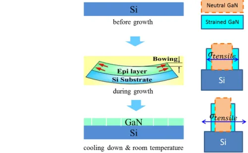
Thermal expansion coefficient (TEC) mismatch causes thermal mismatch stress in heterostructure. Stress arises in hetero-multilayer when temperature ramps, for example temperature ramps during growth and cooling down after growth. Due to TEC difference, layers would expand or shrink with different rates and cause the change of LC mismatch. The
case of GaN on Si is shown in Fig. 1.2. TEC is also not constant but dependent on
temperature. As plotted in Fig. 1.3, the temperature dependent TEC of GaN is always higher
than that of Si. Consequently, the LC difference between them decreases as temperature rises. 𝜖𝜖𝑇𝑇ℎ= ∫�𝛼𝛼𝑠𝑠(𝑇𝑇) − 𝛼𝛼𝑓𝑓(𝑇𝑇)�𝑑𝑑𝑇𝑇 (1-5) 0 300 600 900 1200 1500 1.0x10⁻⁶ 1.5x10⁻⁶ 2.0x10⁻⁶ 2.5x10⁻⁶ 3.0x10⁻⁶ 3.5x10⁻⁶ 4.0x10⁻⁶ 4.5x10⁻⁶ 5.0x10⁻⁶ 5.5x10⁻⁶ 6.0x10⁻⁶ 6.5x10⁻⁶ T E C (K -1 ) Temperature (K) Si GaN
Fig. 1.3 Temperature dependent thermal expansion coefficients of GaN and Si.
Thermal stress problem for GaN growth on Si occurs after growth during cooling down. Due to larger TEC than Si, lattice of GaN shrinks faster and more than that of Si, then tensile
thermal mismatch stress emerges at GaN. Using Eq. (1-5), the tensile strain occurs in GaN on
Si when the temperature decreases from the growth temperature of GaN at 1300 K to room temperature of 300 K is 0.001755 and the tensile stress could be about 0.79 GPa. But in the real case, bowing caused by thermal mismatch stress is much more significant than that of
Fig. 1.4 Schematic diagram of wafer bowing during growth and GaN cracking during cooling. 7
intrinsic stress caused by LC mismatch stress. Usually, cracking doesn’t happen during
growth but during cooling, as illustrated in Fig. 1.4. Viewed from the point of thermal
expansion coefficient, if we want to compensate the tensile stress between GaN and Si during cooling down, some material with TEC smaller than that of Si is needed to be inserted in between GaN layers. Unfortunately, such material is hardly available using MOVPE.
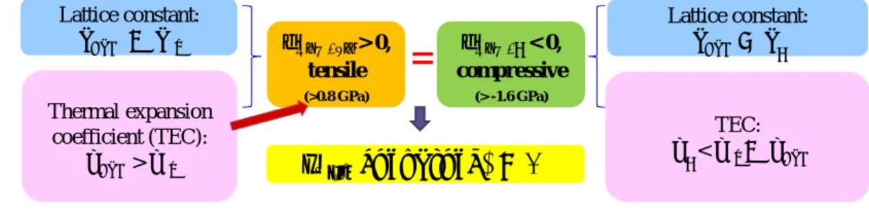
In conclusion, the core of the difficulty for GaN growth on Si is tensile stress arises from both of the lattice constant mismatch and thermal expansion coefficient mismatch. The tensile stress is too large that causes cracks in GaN. The work have to do is how to introduce
compressive stress to compensate it. As summarized in Fig. 1.5, people can apply some
material with LC smaller than GaN to induce compressive stress at GaN layers, or with TEC smaller than Si to produce compressive stress during cooling down. From the discussion above, the only practical route is the former one. AlN is a good candidate. From the calculation in chapter 4, the ideal thermal tensile stress in GaN caused by cooling is around 0.8 GPa. In the structure consists of AlN buffer layer and interlayers, compressive stress is dominantly induced in GaN layers overlying on AlN interlayers and the sum of their thickness is roughly half of the total GaN thickness. As a result, the compressive stress in GaN on AlN interlayers should be larger than 1.6 GPa. On the other hand, quality improvement of GaN is also not straightforward. High quality buffer layer, 3D growth mode and masking and so on can be useful strategies to improve the quality of GaN.
1.3 Status
The research of GaN-on-Si started from the beginning of 2000s [25]. Because GaN cannot grow directly on silicon due to the alloy react between gallium and silicon. AlN is the first step and buffer layer for the growth of following layers. Inserting AlN interlayer (IL) into GaN is the first and simplest solution applied to tune the stress state in GaN [26]. Later some
institute applied thick AlN/GaN super-lattice [27] or grading AlxGa1-xN [28] following AlN
buffer layer to control the tensile stress in GaN, without inserting AlN ILs.
GaN-on-Si is called as the future wafer. It has attracted intensive research from the industry and now the investment is still increasing, including Aixtron, Azzurro, TOSHIBA, Samsung, TOWA, imec, OSRAM and some of them are capable of supplying 8-inch GaN-on-Si wafer. They are aiming at the market of MOVPE systems and LED. GaN with thickness more than 10 um is mandatory to obtain device level quality with full width at half
Fig. 1.5 Summary of the core of GaN-on-Si and possible corresponding strategies.
=
Lattice constant: 𝑎𝑎𝐺𝐺𝑎𝑎𝑁𝑁 < 𝑎𝑎𝑆𝑆𝑆𝑆 Thermal expansion coefficient (TEC): 𝛼𝛼𝐺𝐺𝑎𝑎𝑁𝑁> 𝛼𝛼𝑆𝑆𝑆𝑆 𝝈𝑮𝑮𝒂𝒂𝑮𝑮/𝑺𝑺𝑺𝑺 > 0, tensile (>0.8 GPa) 𝝈𝑮𝑮𝒂𝒂𝑮𝑮/? < 0, compressive (> -1.6 GPa) Lattice constant: 𝑎𝑎𝐺𝐺𝑎𝑎𝑁𝑁> 𝑎𝑎? TEC: 𝛼𝛼?< 𝛼𝛼𝑆𝑆𝑆𝑆< 𝛼𝛼𝐺𝐺𝑎𝑎𝑁𝑁 𝜎𝜎𝑡𝑡𝑒𝑒𝑡𝑡(𝑐𝑐𝑢𝑢𝑜𝑜𝑣𝑣𝑎𝑎𝑡𝑡𝑢𝑢𝑜𝑜𝑒𝑒) = 0 8maximum (FWHM) of X-ray diffraction (XRD) rocking curve around 280 arc sec for (0002) plane. This leads to very long growth time for one wafer (> 4 hours), which is not preferable for the industry and there is still plenty of room for improvement. However, the detailed growth and stress control mechanism is still not yet clarified properly or being hidden, especially the stress evolution during growth.
From the academic community, there are still lots of problems yet remains to be researched. Pioneering work is reviewed here briefly and will be introduced in detail in next chapters. The optimal growth condition for AlN layers is confidential and still in dispute.
(1) AlN buffer layer is the base for following layers and plays a critical role. People have studied the properties of GaN on AlN buffer layers grown under various conditions on Si [25, 29-37]. Most of them just related the growth conditions of AlN buffer layer to the performance of overlying GaN and try to figure out the optimum condition for AlN buffer, especially for the buffer layer consists of AlN and AlGaN multilayers. The adopted condition is not wide enough to cover the range which can yield better result. For example, the growth temperature for AlN buffer mostly was up to 1100 ℃, which actually could be higher. Very few work mentioned the stress evolution in AlN buffer layer and the overlying GaN which is very important and essential to understand the behavior of epi-layers. Raghavan et al investigated the stress in AlN but the growth condition is not optimal and cannot cover all the ranges [32]. Generally there are three types of structures for stress control in GaN-on-Si, as represented in Fig. 1.6. Type 1 is the mostly applied since it is the simplest and represents the basic principle of stress control as well as the role of AlN layers.
Fig. 1.6 Types of previously studied structure of GaN-on-Si, type 1 (mostly applied): AlN buffer and AlN interlayers [38]; type 2: AlGaN/AlN composite buffer layer with or without interlayers [39];
type 3: AlN buffer layer and AlN/GaN superlattices intermediate layer [27].
(2) AlN IL is the main force to introduce compressive stress to GaN layers. The role and growth condition of AlN ILs is much more complicated than that of AlN buffer layer, since it is very thin (~ 10 nm) and much more vulnerable to growth conditions, so that people invested much effort working on it [20, 26, 40-49]. People investigated its effects on following GaN on it. They prefer to use low-temperature AlN IL and found that it has a separating effect in between neighboring GaN layers. But in fact the optimal growth temperature for AlN ILs is not necessarily low. Their adopted conditions including growth temperature, thickness and V/III ratio were not proper to understand the role of AlN IL fully in depth. Especially the direct TEM observation of AlN ILs and the interfaces at them was very less to understand the relaxation mechanism at themselves and GaN layers on them. It is mandatory to observe the
Si (111)
AlN AlGaN
GaN
type 1 type 2 type 3
generation and propagation of dislocation at AlN ILs and through the whole structure. The morphology and misfit dislocation generation at AlN/GaN interfaces is critical to clarify the relaxation processes. The behavior of AlN ILs is far from being well understood and there is still large space to improve the performance of AlN ILs. People have no idea about what is ideal AlN IL.
(3) In the past publications, there was little data of in-situ curvature observation, which is the most accurate, direct and efficient way to access the stress and relaxation behavior of each individual layer. Without in-situ observation, it is hardly possible to know about stress transition directly in every individual layer, the relationship between stress introduction and quality and growth conditions. The ability of AlN ILs grown under various conditions to introduce compressive stress in overlying GaN cannot be accessed neither without in-situ observation. Otherwise people have to evaluate it by ex-situ methods like XRD or curvature measurement after growth, which may easily introduce considerable error if the sample is not delivered carefully.
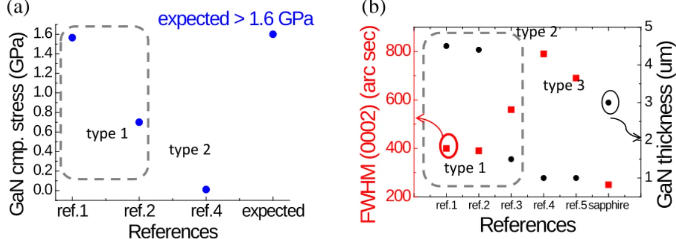
(4) Quantitative theoretical analysis on stress evolution during growth and cooling also has not yet been done. Physics behind stress evolution and defect propagation is not completely clear. However, such knowledge is critical to allow us to design GaN-on-Si with any desired bowing for any device application freely as well as to simplify sample structure and shorten growth time as much as possible. A model for arbitrary wafer bow prediction and curvature simulation is not available. There are very few data about the compressive stress in GaN 𝜎𝜎𝑐𝑐𝐺𝐺𝑎𝑎𝐺𝐺. The limited previous results were summarized in Fig. 1.7a. The desired ideal 𝜎𝜎𝑐𝑐𝐺𝐺𝑎𝑎𝐺𝐺 is > 1.6 GPa and most of them were much lower than that then could not maintain the stress balance in the system. GaN quality was also much lower than that on sapphire.
*ref.1: [49], ref.2: [38], ref.3: [46], ref.4: [50], ref.5: [51].
Fig. 1.7 (a) compressive stress in GaN layers and (b) FWHM of XRD rocking curves of GaN-on-Si from the references*.
type 1
type 2
ref.1 ref.2 ref.4 expected 0.0 0.2 0.4 0.6 0.8 1.0 1.2 1.4 1.6 G aN c m p. s tr es s ( G P a) References expected > 1.6 GPa
(a)
ref.1 ref.2 ref.3 ref.4 ref.5sapphire
200 400 600 800
F
W
H
M
(
0002)
(
ar
c s
ec
)
References
1 2 3 4 5G
aN
t
hi
ck
nes
s (
um
)
type 1 type 2 type 3(b)
101.4 Motivation and targets
As reviewed in the previous section, for the MOVPE of GaN-on-Si, there are still some remaining problems to be researched. The content and targets of this dissertation are listed as follows.
(1) This work is devoted to understanding the growth mechanism of GaN on silicon, including stress control mechanism and quality effects. In detail, it involves the role of AlN buffer layer and AlN ILs, the strain and relaxation process in AlN layers and GaN layers on them, and their stress and quality effects on overlying GaN. One of the targets is to produce AlN interlayers which can induce compressive stress > 1.6 GPa in GaN.
(2) The second target is to build a model to design any desired wafer bow and simulate the in-situ curvature curves based on theoretical strain and stress analysis of each layer, through every stage of a growth.
(3) The third is developing new novel AlN ILs, which can introduce compressive stress in GaN more efficiently than conventional single-layer low-temperature AlN IL.
To achieve the targets above, in this research, the simplest structure is adopted to
understand the growth behavior and build a model. As shown in Fig. 1.8, this structure starts
with AlN buffer layer, and is followed by 1st-GaN, then several AlN ILs are inserted into GaN, and finally it ends with a thick top GaN layer. The strategies or originalities to achieve the targets above are as follows.
(1) High resolution 3-wavelength and 3-beam in-situ curvature monitoring is applied to record the curvature transition and stress evolution during growth and cooling down. (2) Stress and strain relaxation and evolution through AlN and GaN layers is analyzed by
combining the data from in-situ curvature monitoring, transmission electron microscopy (TEM), scanning electron microscopy (SEM), and atomic force microscopy (AFM), XRD rocking curve and reciprocal space mapping (RSM). The stress state and the quality of GaN are related to understand the role of AlN layers. (3) Theoretical analysis of curvature curves are performed to reveal the stress and strain
evolution in GaN layers. Thermal stress during growth and cooling is calculated to fit the curvature curves. Mechanical properties of AlN and GaN layers grown under
Fig. 1.8 Sample structure in this work. 11
various conditions are summarized to build a model to design GaN-on-Si wafer with any bowing.
(4) Based on the idea of ideal AlN IL, original concepts of two-step IL which consists of lower low-temperature AlN and upper high-temperature AlN and pulse-injection AlN IL have been proposed and produced. Two-step AlN IL showed considerable improvement compared with the conventional single-step IL and proved that the assumption of ideal AlN IL was correct.
1.5 Synopsis of this dissertation
Experiments start from chapter 2 in this dissertation, with establishing the growth of GaN growth on Si. GaN growth on Si is not straightforward. There are some obstacles to be cleared before successful GaN growth on Si, including the alloying between gallium and silicon, namely Si melt-back, TMAl pre-flowing and AlN dummy growth. In the ambience of hydrogen, GaN cannot grow on Si directly and it reacts with Si, which is called Si melt-back. The causes of Si melt-back were searched including gallium deposition on Si, the quality enhancement of AlN buffer layer. In chapter 3, the effects of AlN buffer layer and AlN ILs on stress and strain evolution and relaxation mechanism at AlN layers and the overlying GaN were observed, by in-situ curvature monitoring, TEM, AFM and so on. The role of AlN buffer layer and ILs in controlling stress grown under various conditions was analyzed and optimal conditions were searched roughly. Based on the experimental results, a model of ideal AlN IL was proposed. Since then people know that what kind of AlN IL is desired to induce compressive stress in GaN layers most effectively. In chapter 4, based on in-situ curvature observation data, the stress and strain transition in every layer during growth and cooling were analyzed theoretically using Stoney equation, including lattice constant mismatch stress and thermal mismatch stress. After summarizing the mechanical properties of AlN and GaN layer grown under various conditions, a model was built to design the final curvature (bowing) of GaN-on-Si wafer. The problem of plastic deformation of Si substrate was discussed as well. 4-um-thick crack-free GaN on Si was achieved and blue LED was demonstrated on it. In chapter 5, the effects of AlN buffer layer and ILs on the quality of GaN were observed. The quality of GaN also has been improved by 3D growth. In chapter 6, based on the model of ideal AlN IL built in chapter 3, new original AlN IL structures and growth methods were proposed and tested, including pulse-injection-method AlN IL, low-temperature/pulse-injection-method combined two-step AlN IL and low-temperature/high-temperature combined two-step AlN IL. They showed promising result and can compressively stress the overlying GaN more efficiently than conventional single-layer low-temperature AlN ILs. In chapter 7, the content of this thesis was concluded. In the end in appendix, void formation by hydrogen etching in GaN and its effects on stress control and quality and optical properties of GaN were investigated.
References
[1] H.H.G. Limited, Global New Energy Report 2014. 2014. 12
[2] sxcoal.com. Time limit of available fossil energy. 2014; Available from:
http://www.sxcoal.com/ecology/3786029/showarticle.html.
[3] Wikipedia. Wafer (electronics). 2014; Available from:
http://en.wikipedia.org/wiki/Wafer_(electronics).
[4] M. Hadis, Handbook of Nitride Semiconductors and Devices. Vol. 1. 2008, Germany: WILEY-VCH. [5] S. Arulkumaran, G.I. Ng, S. Vicknesh, H. Wang, K.S. Ang, J.P.Y. Tan, V.K. Lin, S. Todd, G.Q. Lo, and S.
Tripathy,Direct Current and Microwave Characteristics of Sub-micron AlGaN/GaN High-Electron-Mobility Transistors on 8-Inch Si(111) Substrate, Jpn. J. Appl. Phys. 51, (2012).
[6] N. Shuji and C. Shigefusa F, Introduction to Nitride Semiconductor Blue Lasers and Light Emitting
Diodes. 2000, Boca, Raton, London, New York, Washington, D.C.: CRC Press. 386.
[7] high frequency optical switch THz, (2013).
[8] H. Sodabanlu,Metalorganic Vapor Phase Epitaxy and Fabrication of 1.5 µm GaN/AlN MQWs Intersubband All-Optical Switches, (2010).
[9] A. Yamamoto, M.R. Islam, T.-T. Kang, and A. Hashimoto,Recent advances in InN-based solar cells: status and challenges in InGaN and InAlN solar cells, physica status solidi (c) 7, 1309(2010). [10] M. Mathew, H. Sodabanalu, M. Sugiyama, and Y. Nakano,Orange/yellow InGaN/AlN nanodisk
light emitting diodes, physica status solidi (c) 10, 1525(2013). [11] 江川孝志, LEDのためのGaN-on-Si技術. 2012.
[12] A. Dadgar, M. Poschenrieder, A. Reiher, J. Bläsing, J. Christen, A. Krtschil, T. Finger, T. Hempel, A. Diez, and A. Krost,Reduction of stress at the initial stages of GaN growth on Si(111), Applied Physics Letters 82, 28(2003).
[13] 2013; Available from: http://www.azzurro-semiconductors.com/.
[14] W.D. Nix and B.M. Clemens,Crystallite coalescence: A mechanism for intrinsic tensile stresses in thin films, Journal of Materials Research 14, 3467(1999).
[15] K.P. O’Donnell, I. Fernandez-Torrente, P.R. Edwards, and R.W. Martin,The composition dependence of the InxGa1−xN bandgap, J. Cryst. Growth 269, 100(2004).
[16] F.K. Yam and Z. Hassan,InGaN: An overview of the growth kinetics, physical properties and emission mechanisms, Superlattices and Microstructures 43, 1(2008).
[17] L. Hsu and W. Walukiewicz,Modeling of InGaN/Si tandem solar cells, J. Appl. Phys. 104, 024507(2008).
[18] A.G. Bhuiyan, A. Mihara, T. Esaki, K. Sugita, A. Hashimoto, A. Yamamoto, N. Watanabe, H. Yokoyama, and N. Shigekawa,MOVPE growth of InGaN on Si(111) substrates with an intermediate range of In content, physica status solidi (c) 9, 670(2012).
[19] K. Takemoto, H. Murakami, T. Iwamoto, Y. Matsuo, Y. Kangawa, Y. Kumagai, and A. Koukitu,Growth of GaN Directly on Si(111) Substrate by Controlling Atomic Configuration of Si Surface by Metalorganic Vapor Phase Epitaxy, Jpn. J. Appl. Phys. 45, L478(2006).
[20] A. Dadgar, M. Poschenrieder, J. Bläsing, O. Contreras, F. Bertram, T. Riemann, A. Reiher, M. Kunze, I. Daumiller, A. Krtschil, A. Diez, A. Kaluza, A. Modlich, M. Kamp, J. Christen, F.A. Ponce, E. Kohn, and A. Krost,MOVPE growth of GaN on Si(1 1 1) substrates, J. Cryst. Growth 248, 556(2003).
[21] L.B. Freund and S. Suresh, Thin film materials. 2003: Cambridge University Press.
[22] J.W. Matthews and A.E. Blakeslee,Defects in epitaxial multilayers. I. Misfit dislocations, Journal of Crystal Growth 27, 118(1974).
[23] J.E. Ayers, Heteroepitaxy of Semiconductors. 2007: CRC Press.
[24] A. Dadgar, M. Poschenrieder, J. Bläsing, O. Contreras, F. Bertram, T. Riemann, A. Reiher, M. Kunze, I. Daumiller, A. Krtschil, A. Diez, A. Kaluza, A. Modlich, M. Kamp, J. Christen, F.A. Ponce, E. Kohn, and A. Krost,MOVPE growth of GaN on Si(111) substrates, Journal of Crystal Growth 248, 556(2003).
[25] S. Zamir, B. Meyler, E. Zolotoyabko, and J. Salzman,The effect of AlN buffer layer on GaN grown on (111)-oriented Si substrates by MOCVD, J. Cryst. Growth 218, 181(2000).
[26] J. Bläsing, A. Reiher, A. Dadgar, A. Diez, and A. Krost,The origin of stress reduction by low-temperature AlN interlayers, Appl. Phys. Lett. 81, 2722(2002).
[27] Z. Liu, X. Wang, J. Wang, G. Hu, L. Guo, and J. Li,The influence of AlN_GaN superlattice intermediate layer on the properties of GaN grown on Si(111) substrates, Chinese Physics 16, 1467(2007).
[28] A. Able, W. Wegscheider, K. Engl, and J. Zweck,Growth of crack-free GaN on Si(111) with graded AlGaN buffer layers, J. Cryst. Growth 276, 415(2005).
[29] H. Lahrèche, P. Vennéguès, O. Tottereau, M. Laugt, P. Lorenzini, M. Leroux, B. Beaumont, and P. Gibart,Optimisation of AlN and GaN growth by MOVPE on Si(111), J. Cryst. Growth 217, 13(2000).
[30] Y. Dikme, G. Gerstenbrandt, A. Alam, H. Kalisch, A. Szymakowski, M. Fieger, R.H. Jansen, and M. Hueken,Investigation of buffer growth temperatures for MOVPE of GaN on Si(111), J. Cryst. Growth 248, 578(2003).
[31] Y. Lu, X. Liu, X. Wang, D.-C. Lu, D. Li, X. Han, G. Cong, and Z. Wang,Influence of the growth temperature of the high-temperature AlN buffer on the properties of GaN grown on Si(111) substrate, Journal of Crystal Growth 263, 4(2004).
[32] S. Raghavan and J.M. Redwing,In situ stress measurements during the MOCVD growth of AlN buffer layers on (111) Si substrates, Journal of Crystal Growth 261, 294(2004).
[33] M. Wu, B.S. Zhang, J. Chen, J.P. Liu, X.M. Shen, D.G. Zhao, J.C. Zhang, J.F. Wang, N. Li, R.Q. Jin, J.J. Zhu, and H. Yang,Effect of the N/Al ratio of AlN buffer on the crystal properties and stress state of GaN film grown on Si(111) substrate, Journal of Crystal Growth 260, 331(2004).
[34] S. Raghavan and J.M. Redwing,Growth stresses and cracking in GaN films on (111) Si grown by metal-organic chemical-vapor deposition. I. AlN buffer layers, J. Appl. Phys. 98, 023514(2005). [35] E. Arslan, M.K. Ozturk, A. Teke, S. Ozcelik, and E. Ozbay,Buffer optimization for crack-free GaN
epitaxial layers grown on Si(1 1 1) substrate by MOCVD, Journal of Physics D: Applied Physics 41, 155317(2008).
[36] W. Luo, X. Wang, L. Guo, H. Xiao, C. Wang, J. Ran, J. Li, and J. Li,Influence of AlN buffer layer thickness on the properties of GaN epilayer on Si(111) by MOCVD, Microelectronics Journal 39, 1710(2008).
[37] M. Wei, X. Wang, X. Pan, H. Xiao, C. Wang, Q. Hou, and Z. Wang,Effect of AlN buffer thickness on GaN epilayer grown on Si(111), Materials Science in Semiconductor Processing 14, 97(2011). [38] P. Drechsel and H. Riechert,Strain controlled growth of crack-free GaN with low defect density
on silicon (111) substrate Journal of Crystal Growth 315, 211(2011).
[39] K. Lin, E.Y. Chang, Y. Hsiao, W. Huang, and L. Tingkai,Growth of GaN film on 150mm Si(111) using multilayer AlNAlGaN buffer by MOCVD, applied Physics Letters 91, 222111(2007).
[40] A. Reiher, J. Bläsing, A. Dadgar, A. Diez, and A. Krost,Efficient stress relief in GaN heteroepitaxy on Si (111) using low-temperature interlayers, J. Cryst. Growth 248, 563(2003).
[41] B.S. Zhang, M. Wu, J.P. Liu, J. Chen, J.J. Zhu, X.M. Shen, G. Feng, D.G. Zhao, Y.T. Wang, H. Yang, and A.R. Boyd,Reduction of tensile stress in GaN grown on Si(111) by inserting a low-temperature AlN interlayer, Journal of Crystal Growth 270, 316(2004).
[42] G. Cong, Y. Lu, W. Peng, X. Liu, X. Wang, and Z. Wang,Design of the low-temperature AlN interlayer for GaN grown on Si (111) substrate, Journal of Crystal Growth 276, 381(2005). [43] S. Raghavan, X. Weng, E. Dickey, and J.M. Redwing,Effect of AlN interlayers on growth stress in
GaN layers deposited on (111) Si, Applied Physics Letters 87, 142101(2005).
[44] J.F. Wang, D.Z. Yao, J. Chen, J.J. Zhu, D.G. Zhao, D.S. Jiang, H. Yang, and J.W. Liang,Strain evolution in GaN layers grown on high-temperature AlN interlayers, Appl. Phys. Lett. 89, 152105(2006).
[45] W. Luo, X. Wang, L. Guo, H. Xiao, C. Wang, J. Ran, J. Li, and J. Li,The effect of low temperature AlN interlayers on the growth of GaN epilayer on Si (111) by MOCVD, Superlattices and Microstructures 44, 153(2008).
[46] D.K. Kim,Influence of the thickness of the 1st GaN layer under a low-temperature AlN interlayer on the properties of GaN layer grown on Si (111), Journal of Crystal Growth 312, 478(2010). [47] R. Luo, P. Xiang, M. Liu, T. Chen, Z. He, B. Fan, Y. Zhao, Y. Xian, S. Huang, Z. Zheng, Z. Wu, H.
Jiang, G. Wang, Y. Liu, and B. Zhang,Influence of V/III Ratio of Low Temperature Grown AlN Interlayer on the Growth of GaN on Si(111) Substrate, Jpn. J. Appl. Phys. 50, 105501(2011). [48] H. Tang, J.M. Baribeau, G.C. Aers, J. Fraser, S. Rolfe, and J.A. Bardwell,Role of buried cracks in
mitigating strain in crack free GaN grown on Si (111) employing AlN interlayer schemes, J. Cryst. Growth 323, 413(2011).
[49] S. Fritze, P. Drechsel, P. Stauss, P. Rode, T. Markurt, T. Schulz, M. Albrecht, J. Bläsing, A. Dadgar, and A. Krost,Role of low-temperature AlGaN interlayers in thick GaN on silicon by metalorganic vapor phase epitaxy, J. Appl. Phys. 111, 124505(2012).
[50] K. Cheng, M. Leys, S. Degroote, B.V. Daele, S. Boeykens, J. Derluyn, M. Germain, G.V. Tendeloo, J. Engelen, and G. Borghs,Flat GaN epitaxial layers grown on Si(111) by MOVPE using step-graded AlGaN intermediate layers, Journal of Electronic Materials 35, 592(2006).
[51] S.-H. Jang and C.-R. Lee,High-quality GaNSi(111) epitaxial layers grown with various Al0.3Ga0.7N/GaN superlattices as intermediate layer by MOCVD, Journal of Crystal Growth 253, 64(2003).
2 Procedure of successful GaN MOVPE on Si
This chapter is about the obstacles to successful GaN growth on Si and the strategies to eliminate them. Basic processes of Si surface cleaning, typical GaN MOVEP on Si procedure and basic characterization methods were introduced firstly in section 2.1. Section 2.2 explored the causes of Si melt-back, including gallium deposition on Si surface, holes in bad quality AlN buffer layer and hydrogen atoms absorption on Si surface. In section 2.3, the effect of TMAl pre-flowing was investigated. In section 2.4, the role and importance of AlN dummy growth to growing high quality GaN on Si was studied. Finally, the necessary measures and standard procedures to yield successful and repeatable GaN growth on Si were summarized in section 2.5.
2.1 Basic procedure of GaN MOVPE on Si
The basic procedure of GaN MOVPE on Si can be described briefly firstly. Samples were grown on 2-inch and 270-um-thick Si (111) wafers by AIX200/4HT-S MOVPE system. Prior to growth, Si wafer was boiled in hydrogen peroxide / sulfuric acid (H2SO4:H2O2=1:1) at 160
℃ for 10 min to remove organic contamination on wafer surface. After 5 min of rinsing in running ultra-pure deionized water, wet cleaning in hydrofluoric acid (HF 5%) at room temperature for 1 min was performed to remove oxide film which would hinder the growth of nitrides on Si. 10 s of TMAl was pre-flowed prior to the AlN buffer layer to avoid nitridation of Si surface. Laser beams at three wavelengths were incident on the wafer to observe surface reflectance during growth. Reflectance at 405.9 nm is mainly applied to detecting the surface roughness. Reflectance at 632.5 and 951.3 nm both could be used to monitor the growth rate and growth mode using optical interference effect. The latter was also used to sense true temperature. Three laser beam spots were used to detect the wafer curvature and asphericity.
In the following part of this section, growth technology, in-situ monitoring and some characterization technologies will be introduced briefly.
2.1.1 Metal-organic vapor phase epitaxy
Metal-organic vapor phase epitaxy (MOVPE) is an epitaxy technology which utilizing metal-organics to carry metal precursors. It was started from the work of Manasevit in 1968 [1] and in the beginning it was also called as metalorganic chemical vapor deposition (MOCVD) to emphasize the vapor chemical reaction. Initially, the film quality by MOVPE was much worse than that of the film grown by other methods like liquid phase epitaxy (LPE). In 1975, thanks to the enhancement of source purity and improvement of growth
process, homo-epitaxial GaAs with electron mobility of 120000 cm2/(𝑉𝑉 ∙ 𝑠𝑠) under 77 K was
grown successfully by MOVPE [2]. After that, lots of people started to work on GaAs field effect transistor [3, 4], GaAs/GaAlAs injection laser in 1978 [5] and high efficiency solar
cells in 1980 [6] based on the growth technology of MOVPE. Since then, MOVPE attracted great interest from the academic community; it succeeded in growing AlInP and AlGaInP which could not be grown by other methods such as LPE and chloride or hydride vapor phase epitaxy. It was widely applied to producing red or yellow light emitting diodes (LED), red laser and high-efficiency solar cells. The most exciting breakthrough made by MOVPE was the success of growing the first p-n junction GaN blue LED in 1989 [7]. Until now, it has been proved that MOVPE is the best method to grow AlGaInN.
As mentioned above and illustrated in Fig. 2.1, in MOVPE, carrier gas H2 or N2 carries the
metal-organic and/or hydrides continuously to the area of heated substrate in the reactor, and the epitaxial layer is formed on the surface of the substrate. Group-III and group-V precursors convect prior to arriving the area of substrate. There are two steps of reaction, including diffusion and reaction in vapor phase and on the substrate surface. The mechanism of vapor phase reaction is very complicated due to there are many types of intermediates of precursors. Adsorption and desorption of product atoms happens simultaneously. In order to achieve film growth, the adsorption rate should be higher than desorption rate.
Fig. 2.1 Schematic diagram of MOVPE reactor and reaction processes.
As represented in Fig. 2.2, MOVPE is a big and complicated system. It consists of five
subsystems, which are control system, gas supplying system, reactor system, in-situ monitor system and tail gas treatment system. Control system controls and monitors every action of the whole system. It consists of a computer, operating software and I/O operators. The reactor system is the core of a MOVPE system. Every other subsystem serves it to yield high quality product. The design of the reactor determines the quality of epitaxial films and production efficiency. Depending on the design of the reactor, MOVPE systems can be classified into several types. The basic method based on the volume of the reactor classifies the MOVPE systems into research type and industrial production type. Depending on the operating pressure of the reactor, they can be classified into atmosphere-pressure MOVPE and
pressure MOVPE. The gas supplying system operates to feed the reactor with purified and flow rate controlled carrier gas, hydride source and metal-organic source. In-situ monitoring system is indispensable to monitor the growth when it is being performed and to collect the most important information of the growth such as growth mode, growth rate, surface roughness, growth temperature, curvature transition, wafer asphericity and so on. Finally, the tail gas after reaction which may contains toxics needs to be treated ahead of it is discharged into the atmosphere.
Fig. 2.2 Illustration of the construction of MOVPE system.
2.1.2 In-situ curvature monitor
In the previous part, it has mentioned that in-situ monitor subsystem is a critical part of a MOVPE system to collect the most important growth information. In this work, the up to date type of in-situ monitor has been applied and would be introduced here. There are light beams of three wavelengths at 405.9 nm, 632.5 nm and 951.3 nm respectively to monitor the growth. The light beam of wavelength of 405.9 nm monitors the growth rate of AlN and the surface roughness of GaN. For the large bandgap of AlN, its growth oscillation pattern is more sensitive to the light of short wavelength. On the other hand, if the reflectance value is higher when the oscillation pattern at wavelength of 405.9 nm goes to constant stage, it means the film surface is smoother. The light beam at wavelength of 951.3 nm watches the growth mode and growth rate of GaN layer. More importantly, it detects the true growth temperature at the wafer surface. The information from the light beam at wavelength of 632.5 nm is similar to that obtained by 951.3-nm light. It is more useful to access the information of AlGaN growth.
The other very important information during MOVPE, especially for the growth of GaN on Si, is the film curvature or wafer bowing. Strain and stress at every individual layer can be calculated by measuring curvature. Curvature monitoring is critical for the performance of some devices such as solar cells and LEDs which contain quantum well structures. Residual stress in nano-structures such as quantum wells may lead to variation of bandgap profile in them and then the performance of the devices. In epitaxial thin film growth, substrate wafers often suffer convex or concave bending due to intrinsic growth stress or thermal mismatch stress. Such wafer bowing should be limited less than safe value, otherwise, it may cause cracking in the film or even with the substrate itself, or the performance of epitaxial film or the device structure might be deteriorated due to too large residual stress. Therefore, it is necessary to monitor wafer bowing during growth and cooling down, namely, the curvature.
Fig. 2.3 Schematic diagram of 3-beam in-situ curvature monitor [8].
The mechanism of curvature monitor was represented in Fig. 2.3a. The distance between
parallel incident light beams would vary after being reflected by the bowing substrate. As
illustrated in Fig. 2.3b, the new type curvature monitor applied in this work has three laser
beams and can promote the accuracy of curvature measurement because it samples the wafer bowing information from more areas than conventional type with only two operating light beams. The three-beam monitor can capture other important information, wafer asphericity, which the two-beam type cannot access. In some cases, for example, GaN growth on Si, if the epilayer is too thick and the Si wafer suffers too much stress, plastic deformation may happen and it deforms asymmetrically which may introduce negative effects to the wafer and device performance. Therefore, asphericity should be monitored and plastic deformation should be avoided. If there is a sudden increasing jump of asphericity, it indicates plastic deformation has started. Some special treatment about the wafer or growth process has to be introduced to eliminate plastic deformation.
After growth, the sample should be characterized ex-situ to check its surface morphology, crystal quality and so on. As examples, two characterization technologies, scanning electron microscope (SEM) and X-ray diffraction (XRD) would be introduced briefly as follows.
2.1.3 Scanning electron microscope
A scanning electron microscope is a type of electron microscopes. It is based on the interaction between electron beams and the observed objects. When a high-energy incident electron beam bombards the surface of the material, secondary electrons, Auger electrons,
![Fig. 3.4 Schematic diagram of threading dislocation and misfit dislocation. (a) Misfit dislocation structure [1]; (b) formation of threading dislocation and misfit dislocation by the glide of half-loops from the surface of the epilayer [1]; (c) bending o](https://thumb-ap.123doks.com/thumbv2/123deta/8495089.922388/56.892.88.765.111.533/schematic-dislocation-dislocation-dislocation-formation-threading-dislocation-dislocation.webp)
