Numerical and Experimental Study On Pull-out Behaviour of Stud Shear Connector Embedded in Concrete
by
Siwei LIU
*, Hiroshi MATSUDA
**, Yuqing LIU
*, Chihiro MORITA
***and Keneta YAMAMOTO
***In steel-concrete composite beams, stud shear connectors are commonly used to transfer the longitudinal shear force across the steel flange/concrete slab interface. In some structures, however, headed studs could be subjected to huge tensile loading during life-span of structures. In this paper, the pull-out behaviour of stud shear connector is studied using both experimental and numerical methods.
In experimental study, a standard pull-out test procedure was proposed and twelve full-scale specimens were manufactured and tested to determine pull-out load-displacement curves. Depending on the stud heights, all specimens were divided into four groups with 3 specimens in each group. In each group, two specimens were carried out under a monotonic loading and one was conducted subjected to a repeated loading pattern. Two kinds of failure mode, concrete cone failure and stud shank failure, were observed in these tests. The resulting monotonic load-displacement mechanism is studied as a 3D problem using finite element analysis software, DIANA. The FEA results are found in good agreement with the test results. All experimental and FEA results demonstrate that specimens with long headed studs have good performances of ultimate strength and ductility.
Key words: Headed stud, Shear connector, Pull-out test, Ultimate capacity, Numerical analysis
1. Introduction
Steel-concrete composite beams are widely used in modern buildings and bridges in recent decades. The shear connection between steel beam and concrete slab is of great importance as it resists separation and transmits longitudinal shear force between the two.
Headed stud shear connectors are the most common type of shear connectors and are used in composite structures due to their easy and rapid construction and non-directional properties subjected to shear force1). Generally, headed studs are mainly designed to transfer large shear force and little pull-out force across the steel-concrete interface. But in some cases, especially in composite bridges with long cantilever slabs, the connectors could be subjected to huge
tensile loading under heavy traffic loads which can not be neglected2).
Since 1960s, a number of experimental and theoretical studies have been carried out to predict the pull-out strength of headed stud connectors3-7). Some strength formulas have been derived by assuming that the stud subjected to pull-out loading would fracture with conical shear surface3). Those equations show that the pull-out strength not only depend on the resistance of the concrete against cracking induced by high stress concentration, but also have relationships with the embedment depth, stud head diameter and steel tensile strength. Those previous studies mainly focused on the ultimate pull-out strength of headed studs embedded in
Received on Jun. 27, 2008
* Department of Bridge Engineering, Tongji University, China
** Department of Structural Engineering
*** Graduate School of Science and Technology
low-strength concrete, and the mechanical behaviour of headed studs under repeated pull-out loading has not been studied.
The objective of this paper is to investigate the ultimate strength, stiffness, ductility and the failure mode of stud shear connectors embedded in high strength concrete. Based on the previous researches1-6), a standard pull-out test procedure is proposed and twelve full-scale specimens are tested to determine the load-displacement curves subjected to monotonic and repeated pull-out loading. A finite element method is also used in this paper to analyze the failure process and predict the pull-out strength.
2. Experimental study 2.1 Specimen description
A total of twelve specimens are designed identically except that the heights of studs are varied.
According to the stud heights of 100, 200, 300 and 400mm, all the specimens are divided in 4 groups named ST-1, ST-2, ST-3 and ST-4. The specimen is constructed from a concrete slab, a steel loading beam and a 22mm diameter headed stud which connects the concrete slab and the steel loading beam together. Main characteristics and dimensions of the test specimen are shown in Fig. 1.
Fig. 1 Diagram of pull-out specimen
As shown in Fig. 2, a steel H-beam with stiffeners is used for the steel loading beam. On one the upper flange, two 200×200mm square holes are reserved for applying the pull-out loads by hydraulic jacks, and one headed stud is welded in the middle of it.
The concrete slab is 700mm long, 500mm wide and 500mm high. Reinforcements of 16mm in diameter are placed around the headed stud to simulate the
actual situation in structures. Moreover, a thin layer of lubricating oil is interposed along the steel-concrete interface in order to avoid bonding.
Fig. 2 Steel loading beam
Normal density aggregates and ordinary Portland cement are used in the concrete mixture and the steel loading beams are manufactured from the same batch of rolled steel Q345. All concrete slabs are cast at the same time and stored in the same curing conditions.
Hence, all the specimens have the same material properties. The 28-day average cube compressive strength of the concrete specimen is 62.5MPa, determined by standard concrete cube test performed on three concrete cube specimens with the height of 150mm. High-performance steel with ultimate tensile strength of 519MPa is used for the steel headed studs.
2.2 Test procedure
The arrangement of pull-out test is shown in Fig. 3.
The pull-out load is applied by two hydraulic jacks placed between the steel loading beam and concrete slab. Two displacement transducers are placed between steel and concrete to measure the vertical displacement. All information is automatically recorded by a data acquisition system at regular intervals during the test.
Load controls are used in all the monotonic and repeated loading tests. For tests with monotonically increasing load, the loading rate is as a constant of 0.05kN/s. The specimens are loaded continuously to the peak strength and the softening stage. All the test data are recorded continuously until the load fell below 85% of the peak load.
The other failure mode is stud shank failure, which occurs when the headed stud is embedded deeply and the strength of concrete is relative high. This kind of failure is significantly different from the concrete cone failure. When the pull-out loading reaches the ultimate strength, the headed stud yields and no concrete failure is observed. The concrete cone failure is observed in groups ST-2, ST-3 and ST4.
Fig. 3 Test arrangement
For repeated loading, the principal task is to define a loading pattern realistically representing a stud connector subjected to repeated pull-out loads. A series of loading cycles are carried out using various levels of maximum loads. The maximum loads increase 10kN every cycle until 80% of the peak load which is obtained from the previous monotonic loading test. After that, the specimen is unloaded and reloaded monotonically to ultimate strength.
Fig. 5 Stud shank failure
(2) Load-displacement relationship
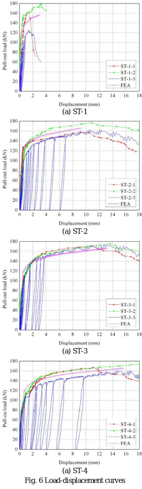
The load-displacement curves of all 12 specimens are shown in Fig. 6. In this experimental programme there are very strong relations among the displacement capacity, the ultimate strength and the observed failure mode.
2.3 Test results (1) Failure modes
As shown in Fig. 4 and 5, two basically different types of failure modes are observed in the tests.
Concrete cone failure occurs when a stud with short shank is adopted in the specimen. Since the stud is not embedded deeply enough, the concrete around the stud cracks and fractures before the stud yield, and the stud is pulled out from the concrete. This failure mode occurs in specimens of group ST-1.
In case of concrete cone failure (ST-1), owing to the short shank of headed studs and the diversity of concrete strengths, the ultimate strengths are not coincident and the measured displacement capacity is relatively low. The displacement suddenly decreases after the peak load and the mean maximum displacement is less than 2 mm. Under repeated load, specimen ST-1-3 has less stiffness and ultimate strength obviously.
The specimens suffered stud shank failure exhibit substantial inelastic deformation before failure. Even after the peak load, they also have sufficient deformation capacity. The maximum displacement at the ultimate load increases with the length of stud shank. In group ST-2, the displacement is about 11mm, exhibiting good ductility.
In groups ST-2, ST-3 and ST-4, the specimens subjected to repeated load have relative consistent load-displacement curves with the corresponding Fig. 4 Concrete cone failure
specimens under monotonic load. Stud with long shank shows good performance subjected to repeated loads.
(3) Ultimate strength and Stiffness
As can be seen from Fig. 6, though group ST-1 has less ductility, it has almost the same ultimate strength with the specimens of other groups. All specimens have ultimate strength more than 160kN except specimen ST-1-3.
(a) ST-1 In the monotonic load test, the elastic modulus can
be defined as the load at the displacement of 0.2mm divide by 0.2mm. The mean value of modulus in groups ST-1, ST-2, ST-3 and ST-4 are 77.8 kN, 50.0 kN, 61.0 kN and 57.5 kN /mm.
3. Numerical Analysis
Numerical analysis is carried out in order to develop a finite element model for pull-out specimen.
The specimen subjected to monotonic load performed in the precious section is analysed as a 3D problem
using the finite element analysis software, DIANA. (a) ST-2 Since the geometrical symmetry of the specimen,
only one quarter specimen is modeled. The pull-out strengths of the stud and load-displacement relationships are also examined and compared with the experimental results.
3.1 Finite element model
The finite element model is shown in Fig. 7. This model consists of three parts, concrete, steel headed stud and the interface between the two.
(a) ST-3 For the concrete and the steel stud, 15-nodes
isoparametric solid wedge elements and 20-nodes isoparametric solid brick elements with quadric interpolation and Gauss integration scheme are used and shown in Fig.8.
As for the interface between the steel and concrete, 8+8 nodes quadrilateral plane interface elements are adapted to describe the bond behaviour in tangential direction and contact behaviour in perpendicular direction.
(a) ST-4
Fig. 6 Load-displacement curves
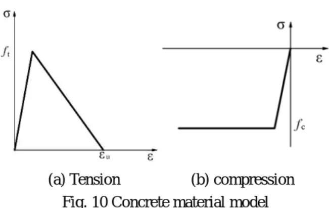
For concrete, the DIANA’s total strain based multiple fixed crack model is adopted and the Drucker-Prager model is used. The Drucker-Prager model has the features such as the tension cut off in tension range and the compressive softening behaviour in compression range. In this model, a liner tension cut off and ideal compression concrete properties are used as showed in Fig 10. The tensile strength ft and compressive strength fc are 2.85MPa and 38.5MPa respectively measured from the tests.
The ultimate tensile strain εu is set to 0.00015 in this paper.
concrete headed stud
Fig. 7 Quarter-symmetry model
(a) Wedge element (b) Brick element Fig. 8 Solid elements
(a) Tension (b) compression Fig. 10 Concrete material model
In DIANA, when tensile stress in the concrete exceeded the pre-set tensile strength ft, the concrete element produces cracks. Once the element cracked, it is no longer assumed to maintain any tensile stiffness unless aggregate interlock is modeled. This is done by reducing the shear stiffness. Kim, B suggested that 40% of the shear stress could be transmitted through the cracked concrete 1).
Fig. 9 Interface element
In order to simulate the realistic constrain acting on the specimen, two groups of restraints are given to the model. One is applied on the two symmetrical surface by the symmetry constrain to ensure the one quarter model can represent the whole specimen. The other is applied on top surface of the concrete where the hydraulic jack acts the compressive force in the test.
A multi-linear constitutive material model is used in steel, in order to express characteristic of the yield plateau and strain hardening behavior of the steel.
The initial elastic modulus of steel is 2.1×10⁵ MPa, the yield strength and ultimate strength are 320MPa and 520MPa.
Since the steel loading beam has not been simulated in the model, the pull-out force is applied at the free end of the shank of stud by a displacement loading.
In the interface element experienced tension, gap arises between the steel and concrete, which means no contact between them. On the other hand, when the faces are in contact, normal forces are developed between the two materials as shown in Fig. 118). The bond behaviour between steel and concrete can be simulated using the bond-slip property of the interface element. According to a study by Anwar Hossain, K.M., the bond strength between concrete 3.2 Material model
The nonlinear mechanisms considered in the models are cracking and crushing of the concrete, the yielding of the steel stud and the bond and contact behaviour of the interface.
and plain bar is primarily derived from friction and seems to be independent of type and age or strength of concrete 9). Owing to the similar surface of steel stud and plain steel bar, a brittle bond-slip curve is used with the ultimate strength 2MPa at the slip 0.003mm.
Fig. 11 Interface behavior in normal direction
3.3 Analytical results and discussion
In order to analyze the influence of the size of studs on the pull-out behaviour of shear connector, four finite element models for the specimens in each group are calculated. The concrete crack patterns and load-displacement curves are obtained from the numerical results.
Fig. 12 and 13 shows the concrete crack strain normal to the crack plane grows corresponding to the displacement loading for group ST-1 and ST-3, which represent two typical failure mode of the headed stud connector under pull-out loading. The simulated concrete crack pattern shows similar crack modes to the concrete pull-out failure surface obtained from the test.
The crack patterns showed in Fig. 12 exhibit the failure process of the specimen embedded with short headed stud. Cracks generate near the stud head at the displacement load of 0.05mm due to the stress concentration. With the increase of applied load, the cracks gradually propagate from the stud head to the end of stud shank. At displacement 0.5mm, the cracks reach the upper surface of the concrete, and after that the crack widths increase until the peak load is reached.
Fig 13 gives a well description to failure process of specimen with longer stud shank. The initial cracks
occur at the displacement load of 0.15mm, which is larger than ST-1, because the bond stresses between steel and concrete share the pull-out load. From the first appearance of cracks to the ultimate strength, the cracks are mainly located at the region encompassing the stud head. Therefore the local failures in concrete do not have a significant influence on the ultimate pull-out strength.
(a) 0.05mm (b) 0.2mm (c) 0.5mm
(d) 1mm (e) 2mm (f) 3mm Fig. 12 Development of crack strain under
various displacement loading (ST-1)
(a) 0.15mm (b) 0.5mm (c) 1mm
(d) 2mm (e) 4mm (f) 13mm Fig. 13 Development of crack strain under
various displacement loading (ST-3)
The load-displacement relationships obtained by the analyses and experiments are compared in Fig.6.
It can be seen that the analytical peak loads and the maximum displacements agree well with the experimental results. The good consistency of analytical and experimental results shows that the finite element method can give a reasonably good prediction of pull-out strength of the stud shear connector.
4. Conclusions
The pull-out behaviour of headed stud connector is investigated by both experimental and numerical method. Based on the test program and analytical results introduced in this paper, several conclusions can be drawn and summarized in the following.
(1) Under equivalent conditions, the failure mode, pull-out strength and ductility of stud shear connectors are significantly influenced by the length of headed stud shank.
(2) Two kinds of failure modes have been observed in the tests. Concrete cone failure occurs when a relatively short shank stud is adopted in the specimen. The stud shank failure happens where the headed stud is embedded deeply enough.
(3) The stud shank failure mode shows good performances in ultimate strength and ductility under monotonic and repeated pull-out loading.
(4) The specimens with long stud shank have higher pull-out strength and better ductility than the ones with short stud shank. According to the test results, the 200mm and 300mm long headed studs are recommendable to use in composited bridges.
(5) For specimen with long headed stud under repeated loading, the ultimate strength keeps the same level with the ones under monotonic loading.
(6) The load-displacement relationships obtained from the finite element model are in good agreement with the experimental data as well as crack propagation patterns. The analytical results show that the finite element method can give a reasonably good prediction of pull-out strength of the stud shear connector.
References
1) Kim, B., Wright H.D., Cairns, R.: The behaviour of through-deck welded shear connectors: an experimental and numerical study, Journal of Constructional Steel Research 57, pp. 1359-1380, 2001.
2) Sasaki, Y., Koyama, A., Yamada, K., Nagai, M.:
Connecting force between concrete deck slab and steel girder at intermediate cross beams in composite two I-girder bridges, Proceedings of JSCE, no.808, pp.75-86, 2006.
3) Hiragi, H., Matsui, S., Sato, T., Al-sakkaf, A., Ishizaki, S. and Ishihara, S.: Pull-out and shear strength equations for headed studs considering edge distance, Structural Engineering/Earthquake Engineering, Vol.20, no.1, pp.69-80, 2003.
4) Ožbolt, J., Eligehausen, R. and Reinhardt, H.W.:
Size effect on the concrete cone pull-out load, International Journal of Fracture, Vol.95, no.1-4, pp.391-404, 1999.
5) Ottosen, N.S.: Nonlinear finite element analysis of pull-out tests, Journal of Structural Division, 107(4), pp.591-603, 1988.
6) Al-sakkaf, A., Hiragi, H., Takabayashi, K. and Matsui, S.: Investigation on pull-out and shear strength of 6mm studs, Proceedings of the Japan Concrete Institute, Vol.23, No1, pp.757-762, 2001.
7) Ohtani, Y. and Fukumoto, Y.: Failure behavior of stud anchor due to pullout tension, Technology reports of the Osaka University, Vol.39, No.1981, pp.297-305, 1989.
8) Matsumura, T. and Mizuno, E.: 3-D finite element deformation analysis of concrete-filled tubular steel column, Finite Elements in Civil Engineering Applications, Swets& Zeitlinger, Lisse, Hendriks
& Rots (Ed.), pp.489-495, 2002.
9) Anwar Hossain, K.M.: Bond characteristics of plain and deformed bars in lightweight pumice concrete, Construction and Building Materials, Volume 22, Issue 7, pp.1491-1499, 2008.