九州大学学術情報リポジトリ
Kyushu University Institutional Repository
ハイブリッド電気自動車とプラグインハイブリッド 電気自動車パワートレインの非線形実時間最適化省 燃費コントローラの一設計法
余, 開江
https://doi.org/10.15017/1398397
出版情報:Kyushu University, 2013, 博士(学術), 課程博士 バージョン:
権利関係:Fulltext available.
A design method of nonlinear real-time optimal controllers to save energy for Hybrid Electric
Vehicle and Plug-in Hybrid Electric Vehicle powertrains
by Kaijiang Yu
A dissertation submitted in partial fulllment of the requirements for the degree of
Doctor of Philosophy
(Electrical and Electronic Engineering) in Kyushu University
2013
Doctoral Committee:
Professor Taketoshi Kawabe, Chair Professor Junichi Murata
Professor Masahito Shoyama
⃝ c Kaijiang Yu 2013
ABSTRACT
In recent years, more ecient and cleaner energy utilization technology has become a research hotspot due to the rising prices of fossil fuels and environmental problems. These lead to the development of hybrid electric vehicles (HEVs) and plug-in hybrid electric vehi- cles (PHEVs). HEVs combine the traditional internal combustion engine, the battery, and the motor/generator as their power plant. Compared with HEVs, PHEVs have an enlarged battery pack and can charge the battery using electricity from an electric grid with a plug.
HEVs and PHEVs (referred as hybrid vehicles later) seem to be the main transitional prod- ucts from internal combustion engine vehicles to battery electric vehicles (BEVs) in the near future. Hybrid vehicles can regenerate dissipation kinematic energy during deceleration and use the redundancy of hybrid vehicle power sources of the engine and the battery to regulate the engine operation to avoid low eciency engine operating points. If the control method is properly designed, hybrid vehicles can get much more fuel economy improvements than those using conventional internal combustion engine vehicles (ICEVs). However, the engine optimal operating point depends on the property of the engine, the surrounding trac con- ditions, the road slopes till the destination, and so on which change every moment. Also, if the battery is operated beyond the battery state of charge limits, this will lead the battery degradation and aect the battery longevity. In the conventional approach, feedback control
methods are presented with a formulation of the optimal control problem for known driving patterns till the destination. In this dissertation, the proposed method can optimize both the engine operating point and the driving prole with 30%-50% of fuel economy improvements by predicting future driving cycles, slopes, and trac information. The topic is addressed in three phases according to the access level of knowledge of future loads.
First, fuel economy improvements in the HEV are conrmed by predicting daily commut- ing driving cycle information using the proposed nonlinear real-time optimal control method.
The apparent relationship between the battery power and the future road load is addressed in the cost function of the fuel economy optimal control problem with a simplied HEV energy management system model. The fuel economy improvements using the proposed ap- proach were conrmed quantitatively compared with those using the rule-based approach.
The entire vehicle operating modes: idle stop, engine charge, engine start, electric vehicle, motor assist and electric continuously variable transmission, and regenerative braking, can be realized using the proposed real-time optimal control approach for HEVs.
Second, fuel economy optimization of HEVs is proposed by predicting future road slopes and trac information. Considering the HEV physical constraints like the speed and torque limits of the engine and motor/generators, and the battery state of charge beforehand makes the optimization and the fuel improvements trustworthy. The real-time optimal control can consider constraints in advance. The performance index can be systematically designed.
This systematic design process can be applicable to other fuel optimization problems. Using the HEV property, the desired battery state of charge is designed according to the road slopes for better recuperation of free regenerative braking energy. The fuel economy is improved due to this desired battery state of charge adaption. The proposed method gives the freedom of vehicle spacing between the preceding vehicle and the host vehicle. The vehicle spacing is
kept above the minimum value, and this gives the freedom of control for vehicle speed variety to get battery fuel economy. This freedom can improve the fuel economy. The superiority of the proposed nonlinear real-time optimal control approach was conrmed compared with the rule-based approach.
Third, the proposed method is extended when the driving distance is unknown. The fuel economy improvements for the PHEV are conrmed with driving distance uncertainty in reality using the proposed nonlinear real-time optimal control method. The proposed controller can be constructed without the trip distance information which is required in the conventional control method.
In total, this dissertation proposed a nonlinear real-time optimal control algorithm for energy management in HEVs and PHEVs. The main contribution is a systematic real- time optimal control approach for energy management in HEVs and PHEVs by predicting future road loads. This systematic design process is useful for signicant fuel economy improvements in the energy management control unit application with minimal hardware cost. The conclusion is that the nonlinear real-time optimal control approach is eective for the energy management problem of the HEV/PHEV system.
DEDICATION
To the people who care about me, and look after me.
To my family.
ACKNOWLEDGMENTS
I am deeply grateful to my advisor, Professor Taketoshi Kawabe for the guidance, support, patience, and encouragement during the past three years. I cannot imagine a better role model using his action to lead me to grow in both academic and personal life. I appreciate this incredible fortunate opportunity very much. I would also like to thank my other committee members, Professor Junichi Murata and Professor Masahito Shoyama, for their helpful advice and comments.
I am great indebted to Dr. Masakazu Mukai for his key feedback on this project, through group laboratory meetings.
I am indebted to the Technical Committee on Automotive Control and Model Research (JSAE and SICE Joint) for their support in implementing the benchmark problem simulator.
Especially I would like to thank Chief Engineer Yuji Yasui for his suggestions and ideas.
It is a great pleasure working in the System Design Laboratory as a doctoral student.
I wish to thank Dr. Md. Abdus Samad Kamal, Dr. Anan Kaku, Peng Zhang, Wenjing Cao, Daisuke Yamaguchi, and other members, for their constructive critical suggestions, discussions, and moral support.
Finally, I want to thank the love and support of my family, my father Deming Yu, my mother Shirong Liu, my grandfather Xuezhi Liu, my grandmother Defang Yang, my younger
brother Kaihai Yu. I would also like to thank my ancee, Qing Liang, for her encouragement, love, and support during these four years.
LIST OF PUBLICATIONS
K. Yu, M. Mukai, and T. Kawabe, Model predictive control of a power-split hybrid electric vehicle system, Articial Life and Robotics, vol. 17, no. 2, pp. 221226, Dec. 2012.
K. Yu, M. Mukai, and T. Kawabe, A battery management system using nonlinear model predictive control for a hybrid electric vehicle, Accepted in the 7th IFAC Symposium on Advances in Automotive Control.
K. Yu, M. Mukai, and T. Kawabe, Model predictive control of a power-split electric vehicle system with slope information, Accepted in the SICE Annual Conference 2013.
TABLE OF CONTENTS
ABSTRACT ii
DEDICATION iv
ACKNOWLEDGMENTS v
LIST OF PUBLICATIONS vii
LIST OF FIGURES xi
LIST OF TABLES xv
LIST OF APPENDICES xvi
Chapter I. Introduction 1
1.1 Research Background and Motivation . . . 2
1.2 Literature review . . . 9
1.3 Key issues and main features of the approach . . . 12
1.4 Contributions and research objective . . . 14
1.5 Dissertation Organization . . . 16
Chapter II. Fuel economy optimization for known daily commuting driving
patterns 17
2.1 Features of the approach for known daily commuting driving patterns . . . . 17
2.2 Modeling and control for the 1 degree of freedom model . . . 18
2.3 Computer simulation results of the nonlinear real-time optimal control algo- rithm with daily commuting driving patterns for HEVs . . . 25
2.4 Discussion for the simulation with known daily commuting driving pattern . 32 Chapter III. Driving cycle and engine operating point optimization for un- known driving patterns 34 3.1 Features of the approach for unknown driving patterns . . . 35
3.2 Modeling and control for the 3 degrees of freedom model . . . 36
3.3 Simulation results for the unknown driving pattern with slope information . 46 3.3.1 Case 1 . . . 47
3.3.2 Case 2 . . . 49
3.4 Simulation results for the unknown driving pattern with slope and trac information . . . 54
3.4.1 Comparison controllers . . . 54
3.4.2 Test road slope proles and calculation of the road slopes and the desired battery state of charge . . . 57
3.4.3 Simulation conditions . . . 58
3.4.4 Simulation results . . . 59
3.5 Discussion for the simulation for unknown driving patterns . . . 69
Chapter IV. Optimal energy management of plug-in hybrid electric vehicles
with uncertain driving distance 70
4.1 Features of the approach with uncertain driving distance . . . 70
4.2 modeling and control for the 1 degree of freedom model . . . 71
4.3 Simulation results with uncertain driving distance . . . 75
4.3.1 Comparison controllers . . . 75
4.3.2 Simulation conditions . . . 76
4.3.3 Simulation results . . . 78
4.4 Discussion . . . 82
Chapter V. Conclusions 87 6.1 Conclusions . . . 87
6.2 Future work . . . 88
Appendices 90
Bibliography 98
LIST OF FIGURES
1.1.1 U.S. crude oil rst purchase price (U.S. Energy Information Administration). 3 1.1.2 Monthly mean atmospheric carbon dioxide at Mauna Loa Observatory, Hawaii
(National Oceanic & Atmospheric Administration). . . 3
1.1.3 Progression of European emission standards (European Commission). . . . 4
1.1.4 Prediction of vehicle transition in the near future, ICEV represents internal combustion engine vehicle, BEV represents battery electric vehicle (Graphic: [1]. . . 5
1.1.5 Graphic depiction of PHEV communication system (Graphic: Business Wire). 6 1.1.6 Hybrid vehicle congurations (Graphic: [9]) . . . 7
1.1.7 PHEV control strategies. . . 8
1.3.1 The concept of the nonlinear real-time optimal control for HEV powertrains with slope and trac information. . . 14
2.2.1 Model of the hybrid electric vehicle. Diagram adapted from [9] . . . 19
2.2.2 The proposed HEV energy management approach . . . 23
2.3.1 The engine OOL of the HEV system . . . 27
2.3.2 Simulation results of the benchmark problem rule-based approach . . . 28
2.3.3 Simulation results of the nonlinear real-time optimal control approach . . . 29
2.3.4 Engine operating point distribution using the benchmark problem rule-based approach . . . 30 2.3.5 Engine operating point distribution using the nonlinear real-time optimal
control approach . . . 30 2.3.6 Detailed simulation results of the benchmark problem rule-based approach . 31 2.3.7 Detailed simulation results of the nonlinear real-time optimal control approach 31 3.2.1 Structure of the nonlinear real-time optimal control system. . . 45 3.3.1 Driving prole of the real-time optimal control algorithm and the ASCD
algorithm in Case 1. . . 49 3.3.2 Power-split prole of the vehicle using the real-time optimal control algorithm
in Case 1. . . 50 3.3.3 Power-split prole of the vehicle using the ADVISOR rule-based algorithm
in Case 1. . . 51 3.3.4 Engine operating point distribution using the real-time optimal control algo-
rithm and the ADVISOR rule-based algorithm in Case 1. . . 52 3.3.5 Driving prole of the real-time optimal control algorithm and the ASCD
algorithm in Case 2. . . 53 3.3.6 Power-split prole of the vehicle using the real-time optimal control algorithm
in Case 2. . . 54 3.3.7 Power-split prole of the vehicle using the ADVISOR rule-based algorithm
in Case 2. . . 55 3.3.8 Engine operating point distribution using the real-time optimal control algo-
rithm and the ADVISOR rule-based algorithm in Case 2. . . 56 3.4.1 Flowchart of the nonlinear real-time optimal control algorithm. . . 61
3.4.2 Driving prole of the vehicle tracking nonlinear real-time optimal control algorithm and the ACC algorithm. PV represents the preceding vehicle, HV represents the host vehicle. . . 63 3.4.3 Power-split prole of the vehicle using the solitude real-time optimal control
algorithm. . . 64 3.4.4 Power-split prole of the vehicle using the xed desired battery SOC vehicle
tracking real-time optimal control algorithm. . . 64 3.4.5 Power-split prole of the vehicle using the vehicle tracking nonlinear real-time
optimal control algorithm. . . 65 3.4.6 Power-split prole of the vehicle using the vehicle tracking ADVISOR rule-
based algorithm. . . 65 3.4.7 Engine operating point distribution using the solitude real-time optimal con-
trol algorithm and the solitude ADVISOR rule-based algorithm. The crosses and the circles denote the engine operating points of the solitude real-time optimal control algorithm and the solitude ADVISOR algorithm, respectively. 66 3.4.8 Engine operating point distribution using the vehicle tracking nonlinear real-
time optimal control algorithm and the car tracking ADVISOR rule-based algorithm. The crosses and the circles denote the engine operating points of the vehicle tracking nonlinear real-time optimal control algorithm and the vehicle tracking ADVISOR algorithm, respectively. . . 66 3.4.9 Engine operating point distribution using the xed desired battery SOC ve-
hicle tracking real-time optimal control algorithm. . . 67
4.3.1 State-of-charge response for the blended and CDCS control strategies on two FTP-72 cycles simulated back-to-back. The blended control strategy is the same as the charge depletion control strategy is this work. Figure referred to [8] . . . 79 4.3.2 Simulation results of the nonlinear real-time optimal control CD approach . 80 4.3.3 Simulation results of the nonlinear real-time optimal control CDCS approach 81 4.4.1 Engine operating points for the blended strategy on a brake specic fuel con-
sumption map, for two FTP-72 cycles simulated back-to-back. The blended control strategy is the same as the charge depletion control strategy is this work. Figure referred to [8] . . . 84 4.4.2 Engine operating points for the CDCS strategy on a brake specic fuel con-
sumption map, for two FTP-72 cycles simulated back-to-back. Figure re- ferred to [8] . . . 84 4.4.3 Engine operating point distribution using the nonlinear real-time optimal
control CD approach . . . 85 4.4.4 Engine operating point distribution using the nonlinear real-time optimal
control CDCS approach . . . 85 4.4.5 Detailed simulation results of the nonlinear real-time optimal control CD
approach . . . 86 4.4.6 Detailed simulation results of the nonlinear real-time optimal control CDCS
approach . . . 86 6.0.1 The engine eciency map to the best engine operating points . . . 92 6.0.2 The engine eciency curve to the best engine operating points . . . 93 6.0.3 The engine fuel consumption rate to the best engine operating points . . . . 93
LIST OF TABLES
2.3.1 Fuel economy comparison results for daily commuting driving patterns, where T is the prediction horizon, ACT represents average computation time per sampling interval, and MCT represents max computation time per sampling interval. . . 32 3.3.1 Fuel economy comparison results for the unknown driving pattern with slope
information . . . 53 3.4.1 Fuel economy comparison results for the unknown driving pattern with slope
and trac information . . . 68 4.3.1 Fuel economy comparison results . . . 82
LIST OF APPENDICES
APPENDIX A: ENGINE FUEL CONSUMPTION MODEL . . . 91 APPENDIX B: SOLUTION OF THE REAL-TIME OPTIMAL CONTROL PROB-
LEM . . . 94
CHAPTER I Introduction
This dissertation addresses nonlinear real-time optimal control algorithms that utilize preview information of driving cycles, road slopes, and surrounding vehicles aiming at fuel economy optimization for hybrid electric vehicles (HEVs) and plug-in hybrid electric vehi- cles (PHEVs). This research subject is motivated by the need to develop more ecient and cleaner hybrid vehicles due to the energy decit and stricter and stricter emission regula- tions. The method is the usage of the redundancy of HEV/PHEV power sources to optimize both the engine operating point and the driving prole. However, the hybrid vehicle system is nonlinear because of nonlinearity of battery, engine, motor/generator dynamics, and the performance index. Also, the future road loads due to road slopes, surrounding trac sit- uations, and so on, change every moment. Therefore, Real-time optimal control is needed for on-line computation due to the unknown of future road loads and the constraints of the power-train components. On-line control of hybrid vehicles was not emphasized in the past because of diculty of prediction of future loads. In the last few decades, vehicle naviga- tion technology using GPS, digital map databases, and laser sensors have been developed quickly. This promotes information usage in the energy management of HEVs and PHEVs.
This dissertation focuses on software design using preview information like road slopes, trip
information, and trac information to optimize fuel economy. The proposed real-time op- timal control algorithms have the potential for real-time implementation of hybrid vehicle control with only software changes. The proposed algorithms computed on-line addresses the energy management problem with predicted driving behavior instead of predened driving cycles. This problem has not been generally explored in the literature.
The remainder of this introduction is structured as follows. First, the research back- ground and motivation are presented. Second, the existing literature concerning this work is reviewed. Third, key issues and main features of the approach are presented. Fourth, the contributions and objective of this work are summarized. Finally, the outline of this dissertation is provided.
1.1 Research Background and Motivation
In recent years, more ecient and cleaner energy utilization technology has become a research hotspot due to the rising prices of fossil fuels and environmental problems. The price of crude oil increases very much in the past (Fig. 1.1.1). The transportation sector accounts for a big part of all the crude oil use. The carbon dioxide emission increases aect the global environment a lot. The monthly mean atmospheric carbon dioxide at Mauna Loa Observatory, Hawaii, is shown in Fig. 1.1.2. To solve the above problems, it is required to develop more ecient and cleaner vehicles.
Concurrent with fuel economy improvement requirements is the more and more strin- gent emission standards. Fig. 1.1.3 shows the progression of European emission standards.
The automotive industry faces challenges of improving vehicle fuel economy and reducing emissions.
Figure 1.1.1: U.S. crude oil rst purchase price (U.S. Energy Information Administration).
Figure 1.1.2: Monthly mean atmospheric carbon dioxide at Mauna Loa Observatory, Hawaii (National Oceanic & Atmospheric Administration).
Figure 1.1.3: Progression of European emission standards (European Commission).
These lead to the development of more fuel ecient hybrid vehicles. Fig. 1.1.4 shows the prediction of vehicle transition in the near future [1]. Hybrid electric vehicles and plug-in hybrid electric vehicles seem to be the transitional products from internal combustion engine vehicles to battery electric vehicles (BEVs). HEVs are promising short-term solutions due to their independence from charging stations. Charging infrastructure has been developed quickly recently. Plug-in hybrid electric vehicles may be a long-term solution to the above problems in the future 40 years from today's viewpoint. PHEVs have been on sale for years.
Hadley and Tsvetkova [2] estimate that by 2030 the market share of BEVs/PHEVs could reach 25%. Compared with traditional HEVs, BEVs/PHEVs have an enlarged battery pack and an intelligent converter [3]. Intelligent converter is a kind of converter to regulate the battery voltage to control the speed of the motor according to some intelligent control algo-
Figure 1.1.4: Prediction of vehicle transition in the near future, ICEV represents internal combustion engine vehicle, BEV represents battery electric vehicle (Graphic: [1].
rithms. Using a plug, BEVs/PHEVs can charge the battery using electricity from an electric power grid, also referred to as "grid-to-vehicle" (G2V) operation, or discharge it to an electric power grid during the parking hours, also referred to as "vehicle-to-grid" (V2G) ( [4] [5]) op- eration. With the introduction of a smart garage, which represents an interface between the transportation network and electric power system, the vehicle charging/discharging infras- tructure and control system can be available widely making the proposed vehicle to building (Fig. 1.1.5) idea viable and economically attractive [6]. A PHEV uses a battery to add an extra degree of freedom for the power sources. It can downsize the internal combustion engine, optimize the engine operating point, use the battery electricity obtained by plugging into the electric grid, and regenerate dissipation kinematic energy during deceleration, which help to improve fuel economy and reduce emissions [7], [8].
There are three kinds of hybrid vehicles. They are parallel hybrid vehicles, series hybrid
Figure 1.1.5: Graphic depiction of PHEV communication system (Graphic: Business Wire).
vehicles and power-split hybrid vehicles (Fig. 1.1.6). Parallel hybrid vehicles have mechani- cal and electric paths to drive the vehicle. Series hybrid vehicles use the engine to generate electricity to drive the vehicle. Power-split hybrid vehicles combine parallel hybrid vehicles and series hybrid vehicles with a power-split device. The main drawback of the parallel con- guration is that it has only a single electrical machine. The battery assisting vehicle driving or the engine charging battery must be selected. As for series hybrid vehicles, since the en- gine operation is independent of the vehicle speed and road loads, it can be operated near its optimal condition. A disadvantage of such a conguration is that the electric machines will reduce the overall power-train eciency. The power-split hybrid vehicle has functionality of both series and parallel hybrid vehicles, and it has more modes to get better fuel economy.
It can split the engine power into a mechanical path and an electrical path. Assuming the vehicle speed is constant, using the generator, the engine speed can be adjusted according to the engine optimal operating line. Using the generator the power split device can move
Figure 1.1.6: Hybrid vehicle congurations (Graphic: [9])
the engine operating point to the engine optimal operating line.
The key technology of PHEVs is its energy management. There are two kinds of control strategies for PHEVs: charge depletion and all-electric charge depletion followed by charge sustenance (see Fig. 1.1.7). The charge sustenance strategy for PHEVs is similar to that for HEVs. The authors of [10] proposed a charge depletion strategy. This strategy can get better fuel economy compared with the all-electric charge depletion followed by charge sustenance control strategy. However this fuel economy improvement is possible if the trip distance has been predetermined for the strategy through either user input or algorithmic prediction. In order not to use the trip distance information, this study presents a control algorithm to operate the engine near the engine best eciency line. When the trip distance and the driving cycle are known, the charge depletion strategy may be the best control strategy. When the trip distance and the driving cycle are not known, the all-electric charge
Figure 1.1.7: PHEV control strategies.
depletion followed by charge sustenance strategy may be the best control strategy. PHEVs are extension products of hybrid electric vehicles. Although a PHEV is similar to an HEV, it needs to have a high capacity battery and a new control strategy that manage the connection with the smart home and the smart grid. To make good use of the smart grid and the smart home, the PHEV battery state of charge needs to be scheduled properly to deplete the battery charge to the expected values, when the PHEV reaches the home or the charging station. Since PHEVs have two energy sources i.e. gasoline energy and battery energy that is larger than BEVs' to be planned. PHEVs have more exibility to be controlled than BEVs. Therefore PHEVs can match for the smart grid use and the smart home use. Using the real-time optimal control algorithm, PHEVs can get better fuel economy with causality, and can deal with uncertainties like destination changes, road slopes, trac conditions, and so on. An HEV maintains the battery's state of charge (SOC) in a narrow operating band during the whole trip. However, in a PHEV maximum energy eciency is achieved if the batteries are depleted to their minimum allowable charge by the end of the trip [11].
1.2 Literature review
A lot of works have been published on the energy management problem of HEV systems.
These approaches are typical in a family of optimal control techniques [12] [24]. They can be subdivided into four categories: numerical optimization, analytical optimal control theories, instantaneous optimization, and heuristic control techniques [25]. The most representative of numerical optimization is dynamic programming (DP) [25] [34]. However DP is based on xed speed patterns which are impossible to get in reality. A kind of analytical optimal control techniques is Pontryagin's minimum principle [35] [39]. It gives necessary condi- tions that the optimal solution must satisfy. It also needs to know the entire driving cycle in advance. The instantaneous optimization includes the equivalent consumption minimization strategy (ECMS) [40] [43]. It is based on instantaneous optimization and is easy to imple- ment in real-time. However it cannot guarantee the optimality over the whole driving cycle.
Heuristic control techniques like rule-based control strategies [44] are robust, but they are impossible to guarantee the optimality. In [45], dynamic programming, quadratic program- ming, and model predictive control (MPC) [46] [53] solutions of HEV energy management problems were presented. A model predictive control approach was used to investigate the energy management problem of a power-split HEV over standard driving cycles in [54] [57].
A new charge/discharge control system for hybrid electric vehicles based on the use of car navigation information was proposed in [58].
The literature related to PHEV energy management problems provides a lot of approaches using the ideas to model and control the powertrain components for better fuel economy. A stochastic optimal control approach for power management in plug-in hybrid electric vehicles was proposed by [8]. A comparison of plug-in hybrid electric vehicle control strategies EV
and charge-depleting was presented by [10]. Energy-optimal control of plug-in hybrid electric vehicles for real-world driving cycles was proposed by [59]. The Gipps car following model was applied to the local road trip modeling of plug-in hybrid electric vehicle power management using historical trac data on at roads in [60]. The authors of [61] proposed a new approach to optimal power management of plug-in hybrid electric vehicles in the charge-depletion mode with driving cycle modeling based on the historic trac information. Both dynamic programming and the equivalent consumption minimization strategy (see [62] [71]) were utilized to optimize the battery state of charge prole with terrain, vehicle speed, and trip distance information for a PHEV power management problem in [11].
Although model predictive control is also in the numerical optimization class, its ad- vantage is its predictive nature. The method can use road trac information in the near future [58] and be applicable to the unxed speed pattern [72] [80]. Based on a simple and accurate model of the system, MPC can provide real-time control for the system. This work refers the model predictive control which has the ability for on-line computation as real-time optimal control. This dissertation examines energy management problems of both HEVs and PHEVs. The fuel economy optimization results of HEVs/PHEVs rely strongly on the future road load. The battery SOC can be scheduled optimally using the future road load. The main part of future road loads in cities is relevant to the car following situation. The main part of future road loads between cities depends on the road slope.
When the slope information in advance is predicted, the battery can be depleted slowly in the PHEV case, or be charged up in the HEV case, before the upslope. So the HEV/PHEV can make best use of the battery charged power to assist the vehicle driving. Then the battery SOC is reduced to be prepared for the upcoming downhill battery charging. At last the battery is charged up by the free regenerative braking energy. These make better use of
the high eciency points of the engine and the regenerative braking energy. The preceding vehicle is assumed to be equipped with an ecological driver-assistance system developed by the authors of [73], and is controlled by a nonlinear model predictive controller proposed by the authors of [81], [82]. Since ordinary drivers have some intelligence, it is more reasonable to assume an eco-driving preceding vehicle (PV) than a conventional proportional-integral controlled preceding vehicle. For example, a driver will accelerate the vehicle before the up slope, and decelerate the vehicle before the down slope to make good use of the vehicle inertia kinetic energy. This intelligent driver behavior was realized by [81]. When this preceding vehicle eco-driving behavior is predicted, the following vehicle can schedule the speed and the vehicle spacing optimally using a nonlinear real-time optimal control approach. Especially for MPC, the future road load can be incorporate in the predictive model to better optimize the future speed prole and energy use. In other words, a decentralized nonlinear real-time optimal control system can be developed to model more real vehicle driving situations to get better fuel economy.
Recently, the vehicle GPS-based navigation technology, digital map databases, and laser sensors have been developed quickly. Prediction of future vehicle road loads like road slopes, and preceding vehicle position and speed is becoming realistic, which was impossible in three decades ago. Research on look-ahead control using the GPS road slope information for the fuel optimization of a conventional powertrain heavy truck was accomplished in [83]. A novel development of an ecological driving system for an internal combustion engine vehicle with a continuously variable transmission (CVT) on roads with up-down slopes using a digital map database was presented in [73]. Both dynamic programming and the equivalent consumption minimization strategy were utilized to optimize the battery state of charge prole with terrain information for an HEV power management problem in [40]. For adaptive cruise
control (ACC), the emphasis is on safely increasing driving comfort rather than increasing road capacity. Therefore normally a constant headway or other safe following policies is used to determine the following distance [84]. In [85], two dierent longitudinal control policies for automatically controlled vehicles were investigated. One was based on maintaining a constant spacing between the vehicles while the other was based upon maintaining a constant headway (or time) between successive vehicles. In the work [81], a nonlinear model predictive control algorithm using a simplied model for a power-split HEV was proposed to optimize the vehicle speed prole and the fuel economy. The engine is assumed always worked along its optimal operating line which was an industrial traditional energy management strategy for commercially available HEVs in [86]. Instead of the above general rule, searching whole areas of the engine fuel consumption map for better fuel economy is also investigated in this work.
Eco-driving involves such things as accelerating moderately (with shift ups between 2000 and 2500 revolutions for those with manual transmissions), anticipating trac ow and sig- nals, thereby avoiding sudden starts and stops; maintaining an even driving pace (using cruise control on the highway where appropriate), driving at or safely below the speed limit;
and eliminating excessive idling dened by [87]. As for this work, the eco-driving is rep- resented by the fuel reduction. The fuel economy is calculated using the fuel consumption during a certain time interval.
1.3 Key issues and main features of the approach
Three key issues of nonlinear real-time optimal controller design to save energy for HEV and PHEV powertrains are addressed in this dissertation.
The st issue is the fuel economy optimization problem for the daily commuting driving cycle. Much of vehicle use is for commuters. The daily commuting driving cycle is usually known. Fuel economy optimization of this kind of vehicles can save much energy. Especially for hybrid vehicles which have the redundancy of power sources using the engine and the battery, the fuel economy can be much better by operating the engine optimally. Also, the battery can regenerate dissipation kinematic energy during deceleration for better fuel economy using the known driving pattern. However, there is a problem that if the battery works beyond the SOC bounds, this will cause the degradation of the battery and aect the longevity of the battery. The feature of the proposed approach is the consideration of the battery SOC constraint in advance and the adaptation of the battery power according to the vehicle power demand. The nonlinear real-time optimal control approach has the advantage for dealing with constraints in a predictive control structure. A new cost term is designed to make best use of the battery for better fuel economy.
The second issue is the fuel economy optimization problem for the unknown driving pattern. In reality, the driving pattern is always unknown. Even in the daily commuting driving cycle, there is some deviation between the prescribed vehicle speed and the real vehicle speed. The power uctuations because of road slopes, surrounding trac conditions, and other uncertain situations make the fuel economy optimization dicult. The feature of the proposed approach is that both the driving cycle prole and the engine operating point are optimized. Another new feature of the proposed is that the proposed control has the freedom of vehicle spacing between the preceding vehicle and the host vehicle. The vehicle spacing is kept above the minimum value, and this gives the freedom of control for vehicle speed variety to get battery fuel economy. Also, the proposed approach has the feature that using the HEV property, the desired battery state of charge is designed according to the road
Figure 1.3.1: The concept of the nonlinear real-time optimal control for HEV powertrains with slope and trac information.
slopes for better recuperation of free braking energy using digital maps (see Fig. 1.3.1).
The third issue is the fuel economy optimization problem for the uncertain driving dis- tance for PHEVs. The driving distance aects the large battery energy usage. However, in reality, the driving distance is always uncertain. This makes the engine operating point optimization dicult. This work proposes a new control approach which makes usage of trip distance information unnecessary. The feature of the proposed approach is that the proposed controller can be constructed without the trip distance information which is required in the conventional control method. This is realized by optimizing the engine optimal operating point near the engine optimal operating line.
1.4 Contributions and research objective
This dissertation provides the solution to the problem based on JSAE-SICE Benchmark problem 2: fuel economy optimization of a commuter vehicle with a hybrid powertrain [88]
and [89] provided by the Technical Committee on Automotive Control and Model Research
(JSAE and SICE Joint). Research on known and unknown vehicle speed patterns is investi- gated in this work. This paper extends HEV/PHEV energy management research by adding ve novel contributions.
First, all of the vehicle operating modes: idle stop, engine charge, engine start, elec- tric vehicle, motor assist and electric continuously variable transmission, and regenerative braking [88] and [89], can be realized using the proposed real-time optimal control approach compared with parts of vehicle operating modes using conventional algorithms [90] and [91].
Vehicles need to adapt to various road loads, therefore, a systematic and causal process of vehicle modeling and control which can be applied to the various vehicle operating modes is necessary.
Second, considering the HEV/PHEV physical constraints like the speed and torque limits of the engine and motor/generators, and the battery state of charge beforehand makes the optimization and the fuel improvements trustworthy. The proposed approach uses logarithm functions to deal with the state constraints and the state variant control input constraint which are required to be dealt in real-time. The nonlinear real-time optimal control approach can consider constraints in real-time.
Third, the modeling and control method can be systematically designed. By analyzing the conguration of the power-split hybrid electric vehicle system, a 3 degrees of freedom control oriented model is developed. The controller is constructed considering just the control objectives and the system constraints which is a nature and causal design process. This systematic design process can be applicable to other fuel optimization problems for HEVs and PHEVs.
Fourth, the proposed method gives the freedom of vehicle spacing between the preceding
vehicle and the host vehicle. The vehicle spacing is kept above the minimum value, and this give the freedom of control for vehicle speed variety to get battery fuel economy. This freedom can improve the fuel economy. This freedom can be obtained by the real-time optimal control.
Fifth, using the HEV property, the desired battery state of charge is designed according to the road slopes for better recuperation of free regenerative braking energy. It is not good for the HEV fuel economy if the HEV reaches the top of a hill with a fully charged battery.
It is dicult to obtain the desired battery state of charge prole from the optimization view.
The fuel economy is improved due to this desired battery state of charge adaption.
The objective of this work focuses on developing systematic utilization of nonlinear real- time optimization control methods for HEVs and PHEVs over known and predicted vehicle speed patterns including preview information such as trip information, road slopes, and trac information.
1.5 Dissertation Organization
The organization of this dissertation is as follows. Chapter I presents the introduc- tion. Chapter II presents the modeling, control, and simulation of hybrid electric vehicles for known daily commuting driving patterns. This model is control oriented for future road load predictions. Chapter III introduces the modeling, control, and simulation of hybrid elec- tric vehicles for unknown driving patterns with both driving cycle optimization and engine operating point optimization. Chapter IV provides the modeling, control, and simulation of plug-in hybrid electric vehicles with uncertain driving distance. Chapter V summarizes the conclusions and possible future research directions.
CHAPTER II
Fuel economy optimization for known daily commuting driving patterns
This chapter presents the modeling, control, and simulation of hybrid electric vehicles for known daily commuting driving patterns. This chapter is organized as follows. Section 2.1 introduces the features of the approach. Section 2.2 presents the modeling and control for the 1 degree of freedom model. Section 2.3 provides the simulation results for known daily commuting driving patterns. Section 2.4 presents the discussion.
2.1 Features of the approach for known daily commuting driving patterns
There are three new features of the nonlinear real-time optimal control approach in the hybrid electric vehicle for known driving patterns.
First, the apparent relationship between the battery power and the future road load is addressed in the cost function of the fuel economy optimal control problem with a simplied HEV energy management system model. The xed vehicle speed pattern can be predicted.
The battery charge can be adapted to the future road load to nd better engine operating points and regenerate more free braking energy.
Second, the battery SOC constraint can be considered in advance in the nonlinear real- time optimal control approach. The nonlinear real-time optimal control approach has the advantage for dealing with constraints in a predictive control structure.
Third, it examines quantitatively the eects of operating the engine at the best eciency operating points of the engine with a continuously variable transmission using a commercially available HEV hybrid electric vehicle energy management electronic control unit simulator.
The power-split architecture addressed in this work can regulate engine operating points near it best ecient line.
The engine dynamics aects fuel consumption, therefore the engine dynamics needs to be considered for accuracy. Since the system may become too complex, an approach neglecting the engine dynamics is presented. When the controller is designed, it is assumed that the engine dynamics is neglected compared to the much slower dynamics of the battery [7].
As for the fuel consumption verication, the GT-SUITE engine model is used; the engine dynamics is not neglected. The GT-SUITE engine model contains the cam valve, thermo, intake air, throttle valve, exhaust gas dynamics.
2.2 Modeling and control for the 1 degree of freedom model
A conceptual diagram of the hybrid electric vehicle model is shown in Fig. 2.2.1. The driving condition is a driving pattern of three weeks based on real driving from Honda R&D
Figure 2.2.1: Model of the hybrid electric vehicle. Diagram adapted from [9]
Company to the employee's house. The design specications require that driver's satisfaction parameter that is a function of the dierence between the required vehicle speed and the real speed is above 90%. The HEV in this study has the power-split device which has both functionality of a speed coupler and CVT. There are ve dynamic components: the engine, the battery, two motor/generators (M/Gs), and the wheels in this power-split HEV system.
The MG1 is utilized to shift engine operating points to the engine best eciency line during various road loads.
Since the battery dynamics is the slowest in the power plant, the dynamics of other components in the power plant can be neglected, the system dynamics is dominated by the battery dynamics. Therefore the system dynamics can be reduced to the battery dynamics.
This can simplify the energy management scheme. This approach can also be seen in [7].
This simplication is possible because four constraints are introduced : the road load; the torque and speed relation of the speed coupler; the power ow relation among the ve dynamic components; and the engine optimal operating line (OOL) using CVT. The power plant dynamics can be decomposed to the slow dynamics of the battery model, and the quick dynamics of the engine model and M/G model.
The property of the power-split device, which reveals the torque and speed relationships among the engine, M/Gs, and the road load, can be expressed as follows [92]:
τeng(t) =−(1 + R
S)τM/G1(t)
=−(1 + S
R)(τM/G2(t)− τreq(t) gf )
SωM/G1(t) +RωM/G2(t)−(S+R)ωeng(t) = 0 (2.2.1)
where S and R are the number of the sun gear and the ring gear teeth, respectively;τM/G1, τM/G2, τreq, and τeng are the torque of M/G1, M/G2, the road load, and the engine, respec- tively; ωM/G1, ωM/G2, and ωeng are the angular velocities of M/G1, M/G2, and the engine, respectively; and gf is the nal drive gear ratio.
The power ow relationships among the ve dynamic components at the inverter and the power-split device are given as
Pbatt(t) = PM/G1(t) +PM/G2(t)
Preq(t) = PM/G1(t) +PM/G2(t) +Peng(t) (2.2.2)
where Pbatt, PM/G1, PM/G2, Peng, and Preq are the power of the battery, M/G1, M/G2, the engine, and the road load, respectively.
The engine is assumed to work always along its OOL using CVT which can also be considered as a constraint. When the engine power is known, by looking up the table of OOL, the engine optimal speed and torque can be obtained.
The fuel consumption is approximated using the Willan's line method to reduce the complexity of the engine fuel consumption model. The HEV conguration in this work
can realize idle stop using the electric CVT. It was found that a good approximation was obtained using the Willan's line method [93]. The fuel consumption rate can be expressed as
˙
mf(t) = cf(Preq(t)−Pbatt(t))/(1 +e−β(Preq(t)−Pbatt(t))) (2.2.3)
where cf is a constant. The parameter β decides the shape of the sigmoid function. The sigmoid function is chosen to evaluate the fuel consumption in case of making the vehicle slow down. So the vehicle is near to fuel cut when it slows down. The detailed explanation of this fuel consumption model is included in Appendix A.
The road load is known when the vehicle speed pattern is xed. From the conguration of the power-split HEV system, the M/G2 speed is also known as
ωM/G2(t) = gf
rwvreq(t) (2.2.4)
where rw is the wheel radius; and vreq is the required vehicle speed by the driving speed pattern. This driving cycle required vehicle speed is the desired value of the nonlinear real- time optimal controller.
When the driving speed pattern is xed, the engine and motor/generator dynamics can be neglected, therefore the system dynamics is reduced to the battery dynamics. The only optimization objective is the vehicle fuel economy. The only state variable is the battery SOC,xSOC, and the control input is the battery power. The nonlinear battery model can be
described as follows [35]:
˙
x(t) =f(u(t)) x(t) = xSOC(t) u(t) = Pbatt(t) f(u(t)) = −VOC−√
VOC2 −4Pbatt(t)Rbatt
2RbattQbatt (2.2.5)
wherex andu are the state and the control input, andVOC, Rbatt, andQbatt are the battery open circuit voltage, the battery internal resistance, and the battery capacity, respectively.
As stated in [35], in general, the SOC range of the battery usage is limited between 0.2 and 0.9, but in charge-sustaining problems, the battery mainly operates in a narrower range, e.g.
from 0.5 to 0.7; hence, the voltage and the resistance may not vary so much in the range.
Since an approximate continuous and dierentiable mathematical engine model is needed for the real-time optimal control algorithm, the linear engine model is used as above. How- ever, as for the fuel economy evaluation in the ultimate simulation, the high delity engine model which is a lookup table that provides the engine fuel rate and eciency as a function of instantaneous engine speed and engine torque is used. The other components of the HEV system like the CVT, the power electronics, the two motor/generators are modelled as a lot of lookup tables considering component eciency in the benchmark simulator HEV model.
These lookup tables are measured in a test bench. The approximate models of the engine and the battery for optimal control are used to integrate with the high delity models in the benchmark simulator HEV model.
The simplied modeling method is derived from the power relationships among the en- gine, the battery, and the road load. Since these relationships are general in an HEV congu- ration, this modeling approach explained above can be applied to other HEV congurations.
The optimal controller is divided into two levels. The high-level controller nds the
Figure 2.2.2: The proposed HEV energy management approach
optimal battery power, and the low-level controller determines the optimal torque and speed of the engine and the motor/generators (see Fig. 2.2.2).
The optimal control problem is formulated as
Minimize:J = 1
2(xSOC −xf(t+T))TSf(xSOC −xf(t+T)) +
∫ t+T
t
L(xSOC(τ|t), Pbatt(τ|t))dτ (2.2.6) Subject to:Pbattmin ≤Pbatt(τ|t)≤Pbattmax (2.2.7)
whereT is the prediction horizon; xfis the desired nal state value; and Pbattmin andPbattmax denote the minimum battery power and the maximum battery power.
The objective of this optimal control problem is to minimize the fuel consumption, while the battery SOC is maintained between the thresholds. This is achieved by minimizing the cost function L, which includes four terms: the fuel consumption, the engine use and the mechanical brake use, the deviation of battery SOC from the reference value, and the
penalization of state constraint violations. The cost function L is dened as follows:
L=w1cf(Preq−Pbatt)/(1 +e−β(Preq−Pbatt)) +w2(Preq−Pbatt)2+w3
(1
2(xSOC−SOCd) )2
+w4(−ln(xSOC−SOCmin)−ln(SOCmax−xSOC)) (2.2.8)
where SOCd is the desired battery SOC value; w1, w2, w3 and w4 are the weights; SOCmin and SOCmax denote the minimum battery SOC and the maximum battery SOC. The log barrier function is introduced as a penalizing term for violations of state constraints which are hard to be dealt with. The performance index value becomes very large when the state constraint is being violated. By doing so, the state constraint of the nonlinear system is satised automatically.
The two terms containingPreq−Pbatt have dierent roles. The rstPreq−Pbattterm is for fuel economy evaluation using the Willan's line method. The sigmoid function in the term will lead the fuel consumption to 0 when the vehicle slows down. Since the motor/generator is much more ecient than the engine, the quadratic penalty Preq−Pbatt term is introduced to make best use of the battery energy and avoid using engine power.
Since the future road load is known a priori, the authors believe that it is natural and simple to adapt the battery power to the future road load to obtain better fuel economy.
This relationship is clearly formulized as the second term of the cost function of the optimal control problem. It can make best use of the battery energy buer. The battery can assist the vehicle driving during the acceleration process, and recuperate the free brake energy during the deceleration process. The engine operating points can also be shift to the engine OOL by this adaption.
At each time t, the optimal control input is computed by solving the above optimal control problem during the prediction horizon T. Only the rst element of the optimal control sequence is applied. At the next time step, the prediction horizon moves forward and the process is repeated [95].
2.3 Computer simulation results of the nonlinear real- time optimal control algorithm with daily commuting driving patterns for HEVs
Eectiveness of the above proposed approach is validated by the benchmark simulator, which was provided by the Technical Committee on Automotive Control and Model Re- search (JSAE and SICE Joint) in SIMULINK⃝R and GT-SUITE⃝R [89]. The GT-SUITE engine model which contains the cam valve, thermo, intake air, throttle valve, exhaust gas dynamics has high delity. The fuel economy verication uses the GT-SUITE high delity engine model. In this simulation, vehicle parameters are obtained from the benchmark simu- lator. Fig. 2.3.1 gives the engine OOL of the HEV system. The driving condition is a driving pattern of three weeks based on real driving from Honda R&D Company to the employee's house. The total simulation time is 80456 [s] by the three week HEV driving patterns. The sampling time h is 0.01 [s]. The vehicle parameters are m=1460 [kg], ρ=1.23 [kg/m3], CD=0.33, A=1.746 [m2], g=9.8 [m/s2], µ=0.015, VOC=201.6 [V], Rbatt=0.3192 [Ω] and Qbatt=6.5 [Ah], cf=0.076. The control parameters are β=0.5, SOCd=0.6, SOCmin=0.5, SOCmax=0.7, Pbattmin=−20 [kW], Pbattmax=20 [kW], xf=0.6, Sf=5×10¹¹, w1=920, w2=5× 10⁴,w3=3.5×10⁵, and w4=0.001. The nonlinear real-time optimal control problem is solved
using the numerical computation method: the continuation and generalized minimum resid- ual (C/GMRES) method [96]. A brief description of the solution of the proposed nonlinear real-time optimal control problem is included in Appendix B. The C/GMRES method uses forward dierence approach (shown below), and discretizes the HEV plant with a sampling intervalh to implement the nonlinear real-time optimal control algorithm.
dx
dτ ≈ x(t+τ)−x(t)
τ . (2.3.1)
The rule-based control for HEVs introduces a set of rules to decide the power split between the engine and the battery after the vehicle states are observed. The benchmark problem rule-based control approach is used as a comparison for the proposed nonlinear real-time optimal control approach. The nonlinear real-time optimal control algorithm is realized by utilizing the C MEX S-function builder in MATLAB/SIMULINK. First, the optimal battery power is calculated by the high-level controller. Next, this optimal value is fed into the low- level controller where the optimal torque and speed of the engine and M/Gs are determined.
Finally, these actual control input signals are applied to the commercially available Toyota Prius HEV energy management ECU simulator. The fuel economy is calculated using the benchmark simulator which is based on the GT-SUITE high delity HEV model.
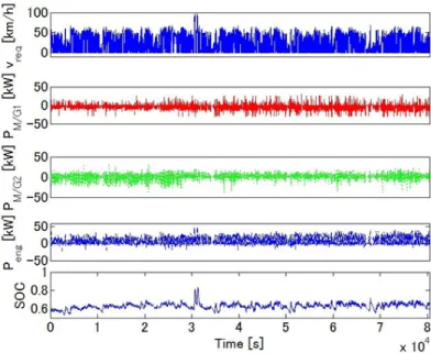
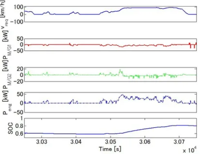
Fig. 2.3.2 shows the simulation results of the benchmark problem rule-based approach.
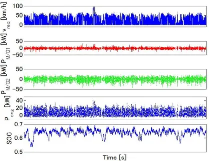
The battery SOC constraint is violated at about 30000 [s] of the simulation. Fig. 2.3.3 shows the simulation results of the nonlinear real-time optimal control approach. The battery SOC constraint is satised during the whole 80456 [s] simulation. In addition, the power of the engine and M/Gs are reasonable according to the commercially available Toyota Prius HEV energy management ECU.
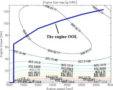
Figure 2.3.1: The engine OOL of the HEV system
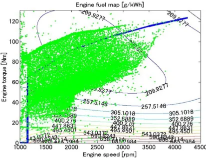
A signicant benet of the power-split architecture is the fact that it decouples the engine crankshaft from the road, and allows the electric machines to move the engine speed where fuel eciency is maximized [97]. This is identied by the engine operating points distribution in Fig. 2.3.4 and Fig. 2.3.5. As shown in Fig. 2.3.5 the nonlinear real-time optimal control approach operates the engine at fairly low speed and high torque, which means high engine eciency and low brake specic fuel consumption values. The nonlinear real-time optimal control approach forces the engine to work regularly, above and close to the engine OOL. In contrast, the benchmark problem rule-based approach operates the engine at fairly high speed and low torque, which means low engine eciency and high brake specic fuel consumption values. By adapting the battery power to the future road load, the nonlinear real-time optimal control approach develops the ability of the power-split architecture to shift the engine operating points to the engine OOL.
The detailed power-split characteristics of the benchmark problem rule-based approach
Figure 2.3.2: Simulation results of the benchmark problem rule-based approach
and the nonlinear real-time optimal control approach is shown in Fig. 2.3.6 and Fig. 2.3.7.
As shown in Fig. 2.3.6, the benchmark problem rule-based approach cannot split the power properly according to the future road load. In contrast, the nonlinear real-time optimal control approach assists the engine when signicant power is requested from the road load, recuperates the free regenerative braking energy during the deceleration period, and runs the HEV in all-electric mode during the cruise period. All of these lead to the improvement of the fuel eciency by making best use of the battery energy buer.
Table 2.3.1 presents the overall fuel economy comparison results. The initial battery SOC of all the cases is 0.6. The nal battery SOC of the benchmark problem rule-based approach is 0.653. The nal battery SOC of the nonlinear real-time optimal control ap- proach is 0.654. Driver's satisfaction parameter is 100% in all the cases. We can see that the nonlinear real-time optimal control approach can improve fuel economy by 34.6% compared to the benchmark problem rule-based approach. The proposed vehicle tracking nonlinear
Figure 2.3.3: Simulation results of the nonlinear real-time optimal control approach
real-time optimal control algorithm is fast for computation. The simulation is run in a Mat- lab/Simulink environment using a laptop with an Intel processor at 2.27 [GHz] processing speed and 2 [GB] of RAM. The sampling interval is 10 [ms]. From Table 2.3.1, it is concluded that the proposed vehicle tracking nonlinear real-time optimal control algorithm has the po- tential for real-time vehicle control. A shorter prediction horizon leads to less computational complexity and computation time. Since the battery dynamics is very slow, there are not many fuel economy improvements when a longer prediction horizon is considered. However, the short prediction horizon is enough for predicting future vehicle acceleration/deceleration to prepare the battery for discharging/charging. The nonlinear real-time optimal control approach can keep the nal battery SOC above the initial battery SOC, which is important to the HEV charge sustainability. These results are promising because the fuel economy is calculated by GT-SUITE high delity HEV model of a real engine, which is the most accurate evaluation method in the computer simulation environment.
Figure 2.3.4: Engine operating point distribution using the benchmark problem rule-based approach
Figure 2.3.5: Engine operating point distribution using the nonlinear real-time optimal con- trol approach
Figure 2.3.6: Detailed simulation results of the benchmark problem rule-based approach
Figure 2.3.7: Detailed simulation results of the nonlinear real-time optimal control approach
Table 2.3.1: Fuel economy comparison results for daily commuting driving patterns, whereT is the prediction horizon, ACT represents average computation time per sampling interval, and MCT represents max computation time per sampling interval.
Method T ACT MCT Fuel economy
[s] [s] [s] [km/l]
Proposed method 0.01 7.7×10⁻⁵ 0.012 25.17(+34.5%) Proposed method 0.02 8.5×10⁻⁵ 0.013 25.18(+34.6%) Proposed method 0.1 1.9×10⁻⁴ 0.012 25.17(+34.5%) Proposed method 1 0.014 0.045 25.18(+34.6%) Proposed method 5 0.0064 0.046 25.17(+34.5%) Proposed method 10 0.0125 0.06 25.18(+34.6%)
Benchmark - - - 18.71
2.4 Discussion for the simulation with known daily com- muting driving pattern
Since the engine and motor/generators dynamics is assumed to be neglectable, the pro- posed controller calculates the optimal power of the engine and motor/generators as manip- ulating variables. Ordinarily, the inertia of the engine is not negligible. In the fuel economy verication, the engine inertia is considered using the GT-SUITE high delity engine model.
From the engine operating point distribution using the proposed approach, it is shown that the engine operating points deviate from the engine optimal operating line because of the delay of the engine. However in the real-time optimal controller, in order to reduce the computation cost, the dynamics of the engine is neglected.
After the optimal battery power is determined by the optimal control algorithm, the engine power can be decided. When the engine power is known, by looking up the table of OOL in the low-level controller, the engine optimal speed and torque reference values can be obtained. The real-time optimal control approach which can use future information can
improve the track ability compared with ordinary feedback control.
CHAPTER III
Driving cycle and engine operating point optimization for unknown driving patterns
This chapter presents the modeling, control, and simulation of hybrid electric vehicles for unknown driving patterns with slope and trac information. This chapter is organized as follows. Section 2.1 introduces the features of the approach. Section 2.2 presents the modeling and control for the 3 degrees of freedom model. Section 2.3 provides the simulation results for the unknown driving pattern with slope information. Section 2.4 provides the simulation results for the unknown driving pattern with slope and trac information. Section 2.5 presents the discussion.
3.1 Features of the approach for unknown driving pat- terns
There are ve new features of the nonlinear real-time optimal control approach in the hybrid electric vehicle for unknown driving patterns.
First, both the driving cycle prole and the engine operating point are optimized using the approach.
Second, considering the HEV physical constraints like the speed and torque limits of the engine and motor/generators, and the battery state of charge beforehand makes the optimization and the fuel improvements trustworthy. The nonlinear real-time optimal control approach can consider constraints in real-time.
Third, the performance index can be systematically designed. The controller is con- structed considering just the control objectives and the system constraints which is a nature and causal design process. This systematic design process can be applicable to other fuel optimization problems for HEVs and PHEVs.
Fourth, the proposed method gives the freedom of vehicle spacing between the preceding vehicle and the host vehicle. The vehicle spacing is kept above the minimum value, and this gives the freedom of control for vehicle speed variety to get battery fuel economy. This freedom can be obtained by the real-time optimal control.
Fifth, using the HEV property, the desired battery state of charge is designed according to the road slopes for better recuperation of free braking energy. It is not good for the HEV fuel economy if the HEV reaches the top of a hill with a fully charged battery. It is dicult to obtain the desired battery state of charge prole from the optimization view. The fuel
economy is improved due to this desired battery state of charge adaption.
In [98]- [100], the authors stated that the conventional engine optimal operating line idea is valid only if the power transmission loss is negligible or if it shows only a mild change throughout the operation condition. However, HEVs have far more complicated and irregular power transmission mechanisms and characteristics than conventional vehicles do. This complexity is mainly due to the electrical power transmission paths which involve non-linear power conversion losses in M/Gs. In other words, HEVs have an energy buer like batteries whose eciency is highly nonlinear to the input road loads. The battery can utilize the free regenerative braking energy to improve fuel economy signicantly. The engine optimal operation for HEVs corresponding to the system optimality needs to be reconsidered. The engine and the motor/generator dynamics is considered for accuracy and global optimality instead of operating the engine near its optimal operating line.
3.2 Modeling and control for the 3 degrees of freedom model
The power-split device property which reveals the torque and speed relationships among the engine, M/Gs, and the road load can be expressed as follows [92], [9]:
IM/G1ω˙M/G1 =τM/G1+f S (IM/G2+ Iw
g2f +mr2w
gf2) ˙ωM/G2 =τM/G2− τresist+τbrake gf +f R
Iengω˙eng =τeng−f(R+S) (3.2.1)
τresist=rwmg(µcos(θ) + sin(θ)) + 1
2ρCDArwv2 (3.2.2)


![Figure 1.1.4: Prediction of vehicle transition in the near future, ICEV represents internal combustion engine vehicle, BEV represents battery electric vehicle (Graphic: [1].](https://thumb-ap.123doks.com/thumbv2/123deta/7599635.2537746/24.918.254.666.165.488/prediction-transition-represents-internal-combustion-represents-electric-graphic.webp)
![Figure 1.1.6: Hybrid vehicle congurations (Graphic: [9])](https://thumb-ap.123doks.com/thumbv2/123deta/7599635.2537746/26.918.251.667.171.493/figure-hybrid-vehicle-congurations-graphic.webp)
![Figure 2.2.1: Model of the hybrid electric vehicle. Diagram adapted from [9]](https://thumb-ap.123doks.com/thumbv2/123deta/7599635.2537746/38.918.282.638.161.352/figure-model-hybrid-electric-vehicle-diagram-adapted.webp)