V ISUAL S UPPORT S YSTEM FOR R EMOTE - C ONTROL C ONSTRUCTION M ACHINE
B ASED ON A UTONOMOUS C AMERAS
無人化建設機械の操縦を支援する 自律的映像提示システムの構築
February 2016
Junjie YANG 楊 俊傑
V ISUAL S UPPORT S YSTEM FOR R EMOTE - C ONTROL C ONSTRUCTION M ACHINE
B ASED ON A UTONOMOUS C AMERAS
無人化建設機械の操縦を支援する 自律的映像提示システムの構築
Junjie YANG 楊 俊傑
Development of Modern Mechanical Engineering, Research on Intelligent Machine Graduate School of Creative Science and Engineering
Waseda University
This dissertation is submitted for the degree of Doctor of Engineering February 2016
A BSTRACT
Considering the high risk of rescue and recovery work in disaster scenes, unmanned construction has been widely used based on remote control. Compared with manned construction, the efficiency of unmanned one is about 40% lower. According to the number of conventional research, insufficient visual information, communication delay, and lack of tactile sense are represented as the three main reasons. Among them, insuf- ficient visual information is ranked first. Blind area, narrow angle of view, no sense of distance and eyestrain are four major reasons causing visual problems. In conventional researches, the most common method is to update the hardware, such like high- resolution monitor, 3D videos, wide-angle lens and etc. By using such method, current visual problems cannot be thoroughly solved, even if the efficiency can be raised indeed.
Thus, I decided to take over this research and try to find a method which can support advanced vision information and solve the visual problems fundamentally and thor- oughly.
This research is conducted in both software aspect and hardware aspect. It is mainly re- alized in three steps according to the order of information process. The first is acquiring most of the necessary visual information in the work site. And then, it will be processed by cameras according to different demand of photography. At last, the processed visible visual information will be displayed together with invisible information by using aug- mented reality prompts. It can make views understandable and enable operator easy to imagine and reconstruct the work site in his/her brain.
Three systems are designed to achieve the three steps. Camera placement system is used to cover most of the work site, which makes required visual information accessible to environmental cameras. By using Autonomous camera control system, environmental cameras can track respective targets by suitable photography method. And videos will be displayed in different viewports properly to make operator easy to understand the meaning and the role of each. Finally, augmented reality (AR) vision prompt system will be embedded in autonomous camera control system. It will calculate the invisible information and display it in the form of prompts with processed videos. In order to ver- ify the effect of later two systems, a virtual reality (VR) simulator was developed.
In camera placement system, environmental cameras should not only be applicable to complicated work site but also meet different demands of photography. By using con- ventional method, it is possible to conduct camera placement on a complicated work
site. However, the local height of different cameras is fixed, which makes it difficult to fulfill the photography demand. Thus, I proposed a novel model, which enable the local height of camera variable. By using the camera model, it is possible to conduct camera placement in 3D world. And it can meet different demand of photography better. It start by loading the terrain condition and required areas in advance. Then, it slides the terrain into meshes and gives the possible vehicle position with the consideration of tilt and smoothness of each mesh. Combining the perspective properties of environmental cam- era, all meaningful camera states are calculated including the position and posture. At last, the system arranges special camera-carried vehicles by trade-off between cost and coverage. By using the system, most of the required area can be covered by environ- mental cameras. It can supply operator with reasonable views to understand work space better. In addition, camera can be changed quantitatively and modified manually to ful- fill photography requirements better according to the result of the system.
In order to supply operator with the views according to the real-time work situation, en- vironmental cameras are designed to be adjustable autonomously. The system is named autonomous camera control system. In the system, the motion of machine is classified into mobility and manipulation. 4 roles of cameras are defined to describe them. 2 of the roles are used to photo the machine the front/back and side. The others are used to photo the manipulator from the front and the side. Environmental cameras positioned in work site in advance are arranged to play these roles. Thus making observation targets be tracked and framed according to the motion of machine. Because the position of each environmental camera is fixed, one camera cannot play a special role all the time.
Therefore, cameras need to switch with others if some of them cannot play the occupied roles. The system is realized through reading the real-time position and posture of con- struction machine as well as the preset environmental information first. These states are used to adjust the postures and magnification of cameras to play the four roles. Some- times, the exchange or rearrangement of camera is conducted to ensure the 4 roles can be always played. By using the system, operators can observe reasonable views of con- struction machine and those of its manipulator to imagine and reconstruct the work site in their brain.
AR vision support system is embedded in autonomous camera control system. It is used to inform operator the invisible information to reinforce the sense of distance. AR prompt items such like arrow and wireframe are displayed in relative views respectively by calculating the situation around construction machine. Distance between obstacle
and machine, drop point of machine, reachable area of manipulator and relationship be- tween joystick and rotation direction are displayed by different augmented reality prompts. In addition, a danger view is introduced to autonomous camera control system, in order to inform operator of the potential danger with AR prompts. By using the sys- tem, operators can understand the work condition better by stronger sense of distance.
Moreover, they can concentrate on the views corresponding to their current action with- out ignoring the danger situation which can maximize their concentration and raise the work efficiency.
As a result, camera placement system succeeds in using the least cameras to show most of the necessary areas of work site. Autonomous camera control system succeeds in processing different visual information according to the demand of photography. It is also able to arrange cameras to ensure that visual information can be always given properly. In AR vision support system, danger view is introduced and AR prompts is able to be displayed with related videos. Eye sight is also be attracted to suitable views as expected according to the situation around controlled machine, which maximize op- erator’s concentration with being aware of dangers. Thus making the performance like efficiency, accuracy and safety of operation better and increasing the user experience while decreasing the misoperation. In addition, the principle of human-friendly AR prompts is made clear, which enable us to design and utilize better prompts in the future work.
C ONTENTS
1 INTRODUCTION ... 17
1.1BACKGROUND ... 17
1.2VISUAL SUPPORT SYSTEM ... 21
1.3REQUIREMENTS ... 24
1.4OBJECTIVE AND SOLUTION ... 24
1.4.1 Accessible visual information ... 25
1.4.2 Clear observation targets ... 26
1.4.3 Human-friendly expression technique ... 27
1.5OUTLINE OF THE FOLLOWING CHAPTERS ... 30
2 CAMERA PLACEMENT SYSTEM ... 33
2.1BACKGROUND ... 33
2.2RELATED WORKS ... 34
2.3PROPOSED MODEL ... 35
2.3.1 Camera model ... 35
2.3.2 Target model ... 39
2.3.3 Environment model ... 39
2.4EVALUATION METHOD ... 41
2.5OPTIMIZATION STRATEGY OF CAMERA PLACEMENT ... 41
2.5.1 Preparation ... 42
2.5.2 Proposed placement strategy ... 42
2.6EXPERIMENT ... 45
2.6.1 Camera carrier and Camera ... 45
2.6.2 Environment and Required Targets ... 45
2.6.3 Results ... 46
2.7SUMMARY ... 48
3 SIMULATION PLATFORM ... 51
3.1REQUIREMENTS ... 51
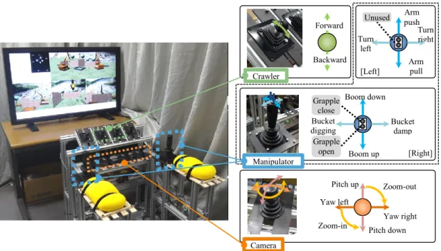
3.2DEVELOPMENT OF MAN-MACHINE INTERFACE ... 52
3.2.1 Hardware ... 52
3.2.2 Software ... 53
4 AUTONOMOUS CAMERA CONTROL SYSTEM... 57
4.1REQUIREMENTS ... 57
4.1.1 Targets ... 57
4.1.2 Display ... 58
4.2ROLES OF CAMERAS ... 59
4.2.1 Analysis of required images depending on situation ... 59
4.2.2 Imaging objects and imaging modes ... 61
4.2.3 Definition of camera roles ... 63
4.3ROLE ASSIGNMENT SYSTEM ... 68
4.3.1 Role Possibility Matrix ... 68
4.3.2 Role assignment system ... 70
4.4EXPERIMENT ... 74
4.4.1 Parameter settings for role assignment system... 74
4.4.2 Experimental conditions ... 75
4.5RESULTS ... 78
4.5.1 Confirmation of the developed autonomous control scheme ... 78
4.5.2 Effectiveness evaluation of the autonomous camera control system ... 80
5 AUGMENTED REALITY (AR) VISION SUPPORT SYSTEM ... 87
5.1IMPROVED OPERATIONAL INTERFACE ... 87
5.1.1 Requirements of improved operation interface ... 87
5.1.2 Improved control system ... 88
5.2AR-BASED ATTENTION INDUCEMENT SYSTEM ... 89
5.2.1 Vertical arrow and guide laser ... 90
5.2.2 Guide laser ... 91
5.2.3 Reachable sphere ... 91
5.2.4 Distance arrow and distance label ... 91
5.2.5 Rotation hint ... 91
5.3EXPERIMENTS ... 92
5.3.1 A. Experimental settings ... 92
5.3.2 Experimental conditions ... 94
5.4RESULTS ... 94
5.4.1 Accomplishment time ... 94
5.4.2 Mental workload ... 96
5.4.3 Frequency of collision ... 97
5.5DISCUSSION ... 98
5.5.1 Questionnaires ... 98
5.5.2 Visual attention inducement ... 100
6 CONCLUSION... 103
6.1CONCLUSION ... 103
6.2FUTURE WORKS ... 104
REFERENCE ... 107
PUBLICATION ... 115
L IST OF T ABLES
TABLE 1PARAMETER VALUE OF PROPOSED CAMERA MODEL ... 46 TABLE 2TRADE-OFF OF PROFIT AND COST ... 48 TABLE 3 RELATIONS BETWEEN REQUIRED OPERATIONS AND IMAGES IN EACH WORK
SITUATION ... 60 TABLE 4EXPERIMENTAL RESULTS OF DIFFERENT CAMERA CONTROL SYSTEMS ... 83
L IST OF F IGURES
FIGURE 1.1TELE-OPERATED AMPHIBIOUS BULLDOZER ... 18
FIGURE 1.2FIRST WIRELESS TELE-OPERATED CONSTRUCTION MACHINE ... 19
FIGURE 1.3TELE-OPERATED CONSTRUCTION BASED ON VIDEOS ... 19
FIGURE 1.4RECOVERY AFTER ERUPTION OF MOUNT USU ... 20
FIGURE 1.5CLASSIFICATION OF THEMES ... 21
FIGURE 1.6TERRAIN MAP, ENVIRONMENTAL MAP AND POSITIONING MAP ... 22
FIGURE 1.7OMNI-VISION DEVICE AND ACQUIRED IMAGE ... 22
FIGURE 1.8DIFFERENT KINDS OF DISPLAY METHOD ... 23
FIGURE 1.9ENTIRE SYSTEM DIAGRAM ... 25
FIGURE 1.10DIFFERENT OBSERVATION TARGETS ... 26
FIGURE 1.11MAXIMUM SCOPE OF MOTION OF A CAR IN DIFFERENT CONDITIONS ... 27
FIGURE 1.12VISIBLE INFORMATION AND INVISIBLE INFORMATION ... 28
FIGURE 1.13SIDE VIEW AND FRONT VIEW OF WORK CONDITION ... 29
FIGURE 1.14GPS VIEW AND CAB VIEW ... 29
FIGURE 2.1DIFFERENT CAMERA TELEVISING DEMAND ... 34
FIGURE 2.2 LINE-OF-SIGHT-BASED SENSOR MODEL ... 34
FIGURE 2.3BASIC PROPERTY 𝒄𝒊 OF CAMERA 𝒊 ... 36
FIGURE 2.4STEPS IN CONFIGURING AND POSITIONING THE VIEWING FRUSTUM ... 36
FIGURE 2.5DIFFERENT PERSPECTIVE PROPERTIES IN 2D VIEW ... 37
FIGURE 2.6PERSPECTIVE OF A CAMERA ... 37
FIGURE 2.7VISIBILITY OF TARGET FROM CAMERA ... 39
FIGURE 2.8SMOOTHNESS AND TILT OF A MESH ... 40
FIGURE 2.9PSEUDO-CODE OF CAMERA PLACEMENT IN OUR STRATEGY ... 43
FIGURE 2.10TERRAIN GENERATED. ... 45
FIGURE 2.11DIVIDED TERRAIN ... 46
FIGURE 2.12POSSIBLE CAMERA POSITIONS ... 47
FIGURE 2.13UPDATED POSSIBLE CAMERA POSITIONS AND REQUIRED TARGETS ... 47
FIGURE 2.14OUTPUTTED CAMERA PLACEMENT PATTERN ... 48
FIGURE 3.1CONNECTION OF HARDWARE ... 52
FIGURE 3.2COMPOSED HARDWARE SYSTEM ... 53
FIGURE 3.3VIEWPORTS CONFIGURATION SAMPLE ... 54
FIGURE 3.4CONSTRUCTION MACHINE PROTOTYPE IN VIRTUAL WORLD ... 55
FIGURE 3.5ADJUSTABLE CAMERA PROTOTYPE ... 55
FIGURE 4.1DIFFERENT MOTION PATTERNS OF MACHINE ... 57
FIGURE 4.2IMAGE OBJECTS ... 62
FIGURE 4.3FUNDAMENTAL IMAGING MODES ... 63
FIGURE 4.4FUNDAMENTAL CAMERA ROLES ... 65
FIGURE 4.5SITUATION IDENTIFICATION AND ADAPTIVE IMAGE RANGE CONTROL ... 67
FIGURE 4.6CHECK OF ROLE POSSIBILITY AND ROLE POSSIBILITY MATRIX ... 69
FIGURE 4.7BASIC CAMERA ROLE ASSIGNMENT RULES ... 71
FIGURE 4.8ADVANCED CAMERA ROLE ASSIGNMENT RULES ... 72
FIGURE 4.9EXPERIMENTAL ENVIRONMENT ... 75
FIGURE 4.10SEQUENCE OF TRANSPORT TASK IN AUTONOMOUSLY-CONTROLLED CAMERA SYSTEM ... 76
FIGURE 4.11 SEQUENCE OF TRANSPORT TASK IN MANUALLY-CONTROLLED CAMERA SYSTEM ... 76
FIGURE 4.12SEQUENCE OF DEBRIS TRANSPORT TASK IN FIXED CAMERA SYSTEM ... 76
FIGURE 4.13 RELATIONS AMONG (A) WORK SITUATION IDENTIFICATION USING SENSOR DATA,(B) EACH CAMERA PARAMETER, AND (C) ASSIGNED CAMERA ROLE ... 79
FIGURE 4.14 TRANSITION AND AVERAGE OF COMPLETION TIME FOR THREE CONTROL SYSTEMS ... 80
FIGURE 4.15 RELATIONS BETWEEN LEVER INPUT AND MACHINE MOVEMENT IN FIXED SYSTEM ... 81
FIGURE 4.16 RELATIONS BETWEEN LEVER INPUT AND MACHINE MOVEMENT IN
MANUALLY-CONTROLLED SYSTEM ... 81
FIGURE 4.17 RELATIONS BETWEEN LEVER INPUT AND MACHINE MOVEMENT IN AUTONOMOUS CAMERA CONTROL SYSTEM ... 82
FIGURE 5.1IMPROVED OPERATIONAL INTERFACE ... 88
FIGURE 5.2INTRODUCED DANGER VIEWS ... 88
FIGURE 5.3DIFFERENCE BETWEEN WITHOUT AR SUPPORT AND WITH AR SUPPORT ... 90
FIGURE 5.4AR VISION SUPPORT SYSTEM DIAGRAM ... 92
FIGURE 5.5WORK SITE ENVIRONMENT USED FOR COMPARISON EXPERIMENT ... 93
FIGURE 5.6WORK TIME IN DIFFERENT SITUATIONS ... 95
FIGURE 5.7AVERAGE MENTAL WORKLOAD OF EACH GROUP ... 97
FIGURE 5.8AVERAGE ERROR CONTACT PER TASK OF EACH GROUP ... 97
FIGURE 5.9QUESTIONNAIRES ABOUT AR VISION PROMPTS ... 99
FIGURE 5.10VISUAL ATTENTION OF EACH DISPLAY ... 100
1 I NTRODUCTION
In our daily life, human beings always use their eyes to obtain visual information. Visu- al information from different perspectives is combined to reconstruct the real world.
Nevertheless, we are still unclear about how human beings achieve it. In many cases, we try to increase the amount of vision to do that. However, the effect does not rise as the number of vision increases.
This paper is intended to reveal some facts in the field of human cognition. And these facts will be applied to solving practical engineering problem.
1.1 Background
No matter the natural disasters or the manmade disasters, they do destroy living envi- ronment [64][66]. And after that, no one knows whether a secondary disaster occurs or not. Usually, we send rescue team to save injured people and dispatch construction team to recover the environment immediately [72]. However, it is tantamount to gambling these team members’ lives. For example, a dangerous goods warehouse was on fire in China’s Tianjin in the night of August 12th 2015. Over 600 firemen were sent to extin- guish the flames immediately. Half an hour later, a series of explosions that killed over 17 and hurt more than 400. Until September 14th 2015, 165 persons were dead including 110 firemen. And 8 persons are still missing.
Even if the rescue team and construction team can come back alive, their mind will probably be tormented by post-traumatic stress disorder (PTSD) in the future. Accord- ing to [1], people from these teams are easy to suffer PTSD for the following four rea- sons:
They are obliged by their occupation.
They are filled with sense of mission.
They have to obey orders from their commanders.
They can devote their lives, which is thought by the public.
In order to realize the same rescue and recovery without endangering more people, we have to utilize some methods which can protect rescue members and construction mem- bers from dangerous scene.
There are two oblivious methods which can achieve that. One is to a shelter which can resist all damage, the other is to keep them far from the dangers or potential dangers.
The previous is hard to achieve. Any one of the existing shelters can only resist several types of damage rather than realize full protection. Thus, tele-operation becomes a more realistic and safer option.
Nowadays, small-scale machines are developed and widely used all around world to search the wounded after earthquake, remove explosive or radioactive materials and etc.
For instances, [2, 3, 4]. Compared with small-scale machines, large-scale machines for recovery and rescue are less developed.
In this field, the corresponding technologies mainly include civil engineering technolo- gy, mechanical technology, imaging technology, wireless communication technology and information communication technology.
In Japan, unmanned tele-operation construction technology was started to be used in 1969. At that time, the pier of a bridge over Jōganji River collapsed. A tele-operated amphibious bulldozer was utilized to conduct recovery work (Figure 1.1). The operator stood on the beach and controlled the machine by wired remote control. The distance is not quite big. As a result, it succeeded to conducting excavation and dozing. [5], [6]
Figure 1.1 Tele-operated amphibious bulldozer
*Referred from [5]
In 1983, tele-operated backhoe was developed and introduced to conduct excavation tasks where there maybe fell some solid or stone. At that time, wireless tele-operation technology was introduced (Figure 1.2). [5], [6]
Figure 1.2 First wireless tele-operated construction machine
From 1970, tele-operation based on video started to be developed. Operator was able to watch the video about first-person perspective of an excavator (Figure 1.3). The video came from the camera which was carried in the cab of excavator by wired data trans- mission. In 1980s, the technology was practically realized. The excavator could success- fully excavate and transport landslides. [5], [6]
Figure 1.3 Tele-operated construction based on videos
Until 1980s, the development of fundamental technologies in tele-operation field had already been basically completed.
In the beginning of 1990s, tens of people died for the pyroclastic flow. In order to avoid secondary disaster, tele-operated recovery has been conducted since 1993. From that time on, tele-operation construction was widely used to conduct disaster response in Ja- pan. These tele-operated machines have to adapt to extreme environments, such like po- tentially extreme temperature (more than 100°C) or long-distance tele-operation (more
Receiver
Transmitter *Referred from [5]
*Referred from [5]
than 100m). At that time, the problems of tele-operated construction gradually revealed, and researchers try to use different methods to solve them. [6]~[13]
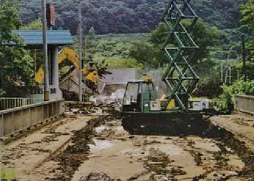
In 2000, Mount Usu erupted. To conduct recovery far from poisonous gas, new wireless communication technologies were introduced, which keeps operators work more than 2km far from the work site. High-power transmitter (2W) was used instead of regular one (0.01W), so that the control signal can be directly transmitted to work machine. In addition, videos were transmitted through relay mobile (Figure 1.4).
Figure 1.4 Recovery after eruption of Mount Usu
Since that, magnificent improvement of tele-operated construction has not appeared.
Most of the improvement can be classified into 2 types. One is to use better devices such as high-resolution monitors instead of old ones [75]. The other is to make work machines do dedicated work more precisely such as piling up bricks [13][76]. Almost no technologies are developed to deal with the problems in regular work. Therefore, op- erators have to handle their regular work with low efficiency. According to [7], [14] and [15], efficiency of unmanned construction work is about 60 percent compared with manned one. In order to make it possible to keep rescue and recovery not only safe but also efficient, the current tele-operation system for large-scale machine has to be im- proved.
In [15], current research themes can be classified as Figure 1.5. According to infor- mation transmission classification method, they can be roughly classified into infor- mation acquisition (including “vision” and “tactile sense”), information communication (including “wireless and radio” and “operation delay”), information manipulation (done by operators) and information output (including “machine and attached facilities” and
“operation method”). Among them, information acquisition takes up 48 percent, which
*Referred from [5]
is far more than other parts. And 60 percent of information acquisition is about vision.
As the basic information of planning and judgment, vision becomes the most important factor compared with others. According to the questionnaire of [16], I found that the main reason causing low efficiency is vision as well. Thus, I believe that vision is im- portant and worthy of study.
[15][15]
Figure 1.5 Classification of themes
1.2 Visual support system
In tele-operation field, visual support system can be divided into the two sections:
i. Information acquisition section
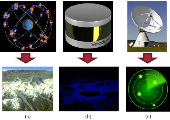
In acquisition section, GPS, radar, laser and different types of cameras are always used derive the position of controlled object. Here, GPS, radar and laser can capture the de- tailed position of object or the rough environment of object. However, it is hard for them to describe the other detailed properties of object, such like posture and color. By using these devices, operators can handle the rough position of object in the whole envi- ronment. In addition, a terrain map of the work site or a rough obstacle position can be also available. In Figure 1.6, it shows the visualized data acquired from corresponding devices. Here, devices of Figure 1.6 (a) and (c) are traditional GPS (Global Positioning System) and radar; device of Figure 1.6 (b) is a 3D LiDAR (Laser Imaging Detection
29%
19%
10%
10%
6%
5%
5%
16%
Research themes
Vision Tactile sense
Machine and attached facilities Wireless and radio
Operation delay Operation method Tele-operation limitation Others
*Referred from [15]
and Ranging) product developed by Velodyne Company, which is widely used in auto- motive, UAV (Unmanned Aerial Vehicle) [8]-[10].
Figure 1.6 Terrain map, environmental map and positioning map
Compared with the above three types of devices, cameras are more commonly used, be- cause the data from it is more intuitive and more detailed. Different kinds of cameras can be used in different scene. The differences among cameras are mainly lens and zooming method. Except the types of lens for regular photography like wide-angle lens or long focus lens, the combination of regular lens and a special mirror is always used to acquire an omni-vision (Figure 1.7). In [11], the device is used to record the environ- ment around the robot.
Figure 1.7 Omni-vision device and acquired image
(a) (b) (c)
*Referred from reibun.skry.info; pixabay.com; www.vboxjapan.co.jp; ambientalsustentavel.org; velodynelidar.com
mirror
lens
light light
*Referred from [11]
There are two types of zooming method. One is optical zooming and the other is digital zooming. Optical zooming is realized by changing the view angle of lens, which makes the image after zooming has the same resolution as that before zooming. It is mainly limited by the corresponding property of lens. Digital zooming is implemented by crop- ping an image down to a centered area with the same aspect ratio as the original, which sacrifices the resolution of image. By using digital zooming, the limitation depends on the noise and amount of resolution after zooming. Low-resolution image cannot de- scribe the object precisely. Usually camera has an optical zoom lens and digital zoom will be automatically applied only if its longest optical focal length has been reached [12].
ii. Information output section
Generally, visual information is always be displayed by monitors or projectors. And sometimes, it can be displayed in different ways. For example, monitor array or curved projection. By using these methods, images or videos can be displayed for dedicated use.
Commonly, monitor arrays are usually used show single extremely big scene or monitor multiple scenes (Figure 1.8 (a) and (c)). Curved projection is mainly used to show pano- ramic view around the observer (Figure 1.8 (b)). In addition, stereo monitor is another choice even if there are still some problems (Figure 1.8 (d)). For example, the over- lapped images.
Figure 1.8 Different kinds of display method
What’s more, how to represent the acquired data is another problem. Visual information can be always displayed as word, graph, image or the combination of them (Figure 1.8 (c)).
A
(a) (b)
(c) (d)
In unmanned construction case, the combination of GPS, cameras and monitor array is a regular way to show visual information.
1.3 Requirements
The Art of War said “if you know the enemy and know yourself, you need not fear the result of a hundred battles.” In my case, it means if operators know the site and machine itself, they can rescue and recover safely and efficiently. In order to achieve that, we have to know the requirement of vision and related factors.
According to [13] and [35], “blind area”, “narrow angle of view” and “no sense of dis- tance” are the three main problems of insufficient vision. Thus, it is easily to be consid- ered that “high coverage of work area”, “wide angle of view” and “more visual infor- mation about distance” are the solution.
In conventional methods, wide-angle lens, big monitors and 3D videos are thought as the solution [14], [35], [69], [75]. By using each method, time efficiency can be raised to some extent. However, both of these methods cannot solve these three problems at the same time. When wide-angle lens is used, the vision area becomes bigger and the wanted visual information seems easier to be available. As the same time, operator’s focus is maybe attracted by other unrelated things. In addition, wide-angle lens cannot make blind area seen and enhance the sense of distance. The later one can enhance the sense of distance, but the other two problems cannot be solved still. What’s more, 3D videos make operators’ eyes easy to feel tired.
Thus, I decided to use software method to solve these problems fundamentally and completely.
1.4 Objective and solution
As the ultimate objective of my method, the above three problems will be solved, and the time efficiency, safety and accuracy can increase obviously. In addition, the visual support system will be improved holistically instead of improving a partial section.
According to my solution, most of work site should be covered as the first step, which means most of the required visual information can be accessible from environmental cameras. And then, each camera will be designed to track object and adjust its magnifi- cation rate according to the size of the object. As the last step, the videos from active cameras will be reasonably processed and arranged on the monitors. At that time, aug-
mented reality elements will be displayed together with related videos, which can en- hance the sense of depth and sense of distance.
In order to realize the objective. Several things should be done.
At first, cameras should be arranged properly according to the balance of cost and cov- erage rate with the consideration of environmental constraints, such like the smoothness of the ground and the possible position of the camera. Then, visual information have to be processed and described properly. Thus clear observation targets and human-friendly expression technique are needed. While acquiring visual information, the camera should make clear what should observe and how to observe it according to photography de- mand. When monitor displays the visual information, the system should tell it what should render and how to render it in a human-friendly way.
Here, three systems shown in Figure 1.9 are designed to achieve each step of my solu- tion, which will be introduced in following chapters. Before that, the detail of each step will be discussed.
Figure 1.9 Entire system diagram
1.4.1 Accessible visual information
In order to make visual information accessible from environmental cameras which are installed in advance, the following essential factors should be considered.
Cameras are a kind of line-of-sight based sensors with limited resolution. Thus, the pho- tography range is limited. And the shape of the photography area should be an over-
High coverage of work site
Wide angle of view
More visual information about distance
Accessible visual information
Clear observation targets
Human-friendly express technique
Camera placement system
Autonomous camera control system
Augmented reality prompt vision support system
lapped section of a pyramid and a ball. They are used to meet different kinds of photog- raphy demands in work site. In most of cases, the work site is not always plain. Some- times, the terrain is quite complicated. Thus, these cameras have to be applicable to complicated terrain. These factors imply that both of the posture and the position of cameras should be thought about before camera placement.
1.4.2 Clear observation targets
When operators control the construction machine, the entire task is always divided into several sub-tasks. For example, when an operator is asked to transport an object and the machine is far from it, the task is always divided into two parts: driving the machine to approach the object and doing the transportation. It is a strategy way of thinking. In such cases, the machine is thought as a particle and the observation target should be the entire work site or a part of it (Figure 1.10 (a)), such like a mini map.
In order to complete each sub-task, it will be divided into several actions. For instance, when the object is reachable, the transportation sub-task will be divided into three ac- tions: picking the object, transporting it and releasing it. This is a tactical way of think- ing. In this case, the machine is treated as an object with volume instead of a particle.
Here the observation target should be a bigger scope including some parts of machine or the entire machine (Figure 1.10 (b)). Except that, a cab view is also thought as a tactical view which is designed to observing the front area of machine. By using this view, op- erator will feel like setting in the machine. And the view is a common selection as well, such as [13], [14][35].
Figure 1.10 Different observation targets Machine Object
Object
Machine
(a) Strategy target (b) Tactical target
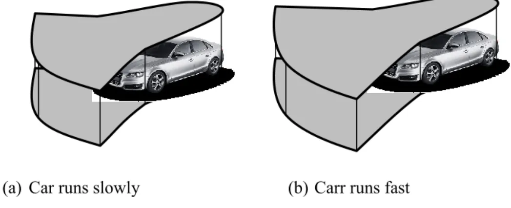
In order to make target easily understandable, the scope of target has to be discussed here. In any case, scene near the machine is the most important. It means the scene in the maximum scope of action with the consideration of operators’ reaction time and re- sponse time. The scope of action is also related to the possible range of motion of the machine during its response time. In Figure 1.11, I give the scope of motion of a car in different conditions. In construction machine case, the scope is more complex and more difficult to predict.
Figure 1.11 Maximum scope of motion of a car in different conditions
A simple method is to give an extremely large scene, which contains the scope of max- imum action of machine. However, this may cause the influx of extra visual information.
Because of the human being’s limitation of processing information, it may increase the difficulty of identifying the related information. It implies that the time cost of pro- cessing visual information increases, which will lead to the low efficiency in both time and accuracy. Contrarily, if the scene is smaller than the scope of action, operator may slow down the manipulation or movement of the machine voluntarily for fear of the un- known. Thus I think a suitable scope of the scene should be one of the most important requirements while developing the vision system.
1.4.3 Human-friendly expression technique
After making visual information accessible and making clear observation targets, the required information should be transformed in a human-friendly way. In this way, oper- ator should observe appropriate views and reconstruct the work site condition in their brain.
By using conventional method, some of views used are not understandable because of the unsuitable scope. And sometimes, some distance is hard to be calculated which may
(a) Car runs slowly (b) Carr runs fast
*Referred from www.drivingfutures.com
cause misjudgement. Thus, a good human-friendly expression method should include not only proper real-time videos but also some prompts which can describe invisible information (Figure 1.12).
Figure 1.12 Visible information and invisible information i. Visible information
In order to making the targets understandable when they are recorded, the number of views and the types of views are quite important. Besides them, how to arrange these views in a monitor is another question.
For cab view and mini map, dedicated devices can be used. In addition, the cab view is mainly designed to make operator immersive and the different directions of a same mini map is meaningless, so only one view is enough to describe either of them.
On the other hand, scope of entire machine or that of some parts of the machine is al- ways recorded from third-person perspective. Several views from different aspects for same scope can be used to describe work condition, which makes operator easily imag- ine and rebuild the scene in his/her brain.
Referring to the views in static cases, we always use at least 2 views like orthographic projections to describe all necessary features of an object, when we make engineering drawing [17] (Figure 1.13). The number of views increases with the increasing com- plexity of object. Sometimes, auxiliary projection, axonometric projection, and section views are also used to illustrate the complicated object.
(a) (b)
Figure 1.13 Side view and front view of work condition
Compared with cases in static conditions, views in dynamic conditions should be more complex. The unrelated information from camera cannot be ignored. And the video changes real-time, which means that operator has to process large amount of visual in- formation all the time during his task. In order to reduce the operator’s pressure of pro- cessing visual information, videos have to be intuitive and understandable. Moreover, operator pays more attention on holistic scene instead of small details. Thus, at least one perspective should be used to describe each scene respectively. In some cases, motion of target is very small. In order to understand the work condition in such cases, 2 views from different directions are recommended.
Types of views should be designed according to the photography requirements for tar- gets. According to [16], [67], cameras carried on construction machine itself are fixed and used to record first-person perspectives about entire front scene including end- effector (Figure 1.14 (b)). And the mini map from GPS system gives the overlook view of the entire work site (Figure 1.14(a)). Thus, the types of views for these two targets have been decided.
Figure 1.14 GPS view and cab view
(a) (b)
For the other targets, same target can be recorded from several different directions. In the last section, 2 views are recommended. Therefore, two views from different direc- tions will be used.
Besides the two factors mentioned above, a good arrangement pattern is quite important.
It makes operator easy to understand the function of each view and handle the work site condition. In principle, views for same scope should be close, and more important views should be closer to cab view. Here cab view is considered as the main view.
ii. Invisible information
Sometimes, it is very difficult for operators to imagine some of invisible data like dis- tance or orientation by using videos only. For example, it is easy to be aware that the machine is near a wall in Figure 1.12 (a). However, it is hard to figure out the rough dis- tance between the wall and the machine without prompts like the arrow in Figure 1.12 (b). Like the arrow here, prompts make operator easy to understand the important invis- ible information without calculation.
However, prompts should not appear everywhere. Too many visual information will make views hard to be understand which may influence operators’ judgment. So, not only the number and the types of prompts but also the corresponding views of them should be thought about.
1.5 Outline of the following chapters
Chapter 2: I will propose a camera model which enable camera to be put in 3D world. According to the model, required observation objects will be designed in 3D world as well. With the consideration of balance between coverage rate and cost, camera placement algorithm will be conducted. And the result shows it is possible to conduct camera placement in a complicated terrain and most of the required area is covered.
Chapter 3: In order to confirm my proposed systems, a simulation platform is built. The software part and the hardware part will be introduced.
Chapter 4: To make camera track the wanted objects autonomously by adjusting its posture and magnification rate, work condition is analyzed at the beginning.
According to that, different observation objects and photography methods are decided. Thus, the roles of cameras are designed. In order to make all roles can be always played, a camera arrangement method is proposed. Comparison
experiment confirmed the good performance in time efficiency, safety, accuracy and user experience.
Chapter 5: Different kinds of augmented reality elements are used to enhance the sense of depth and sense of distance. An danger view is introduced to make the sence more understandable. The result of comparison experiment showed that the good performance in time efficiency, safety, accuracy and user mental pressure. Sight is also be successfully guided to views related to operator’s task.
Chapter 6: Conclude my work and point out the future works.
2 CAMERA PLACEMENT SYSTEM
In this chapter, I proposes a novel sensor model in three dimensional (3D) space. By using this model, it is possible to do line-of-sight-based sensor placement where the height of each camera above ground is variable and the required observation area cannot be treated as a flat surface.
2.1 Background
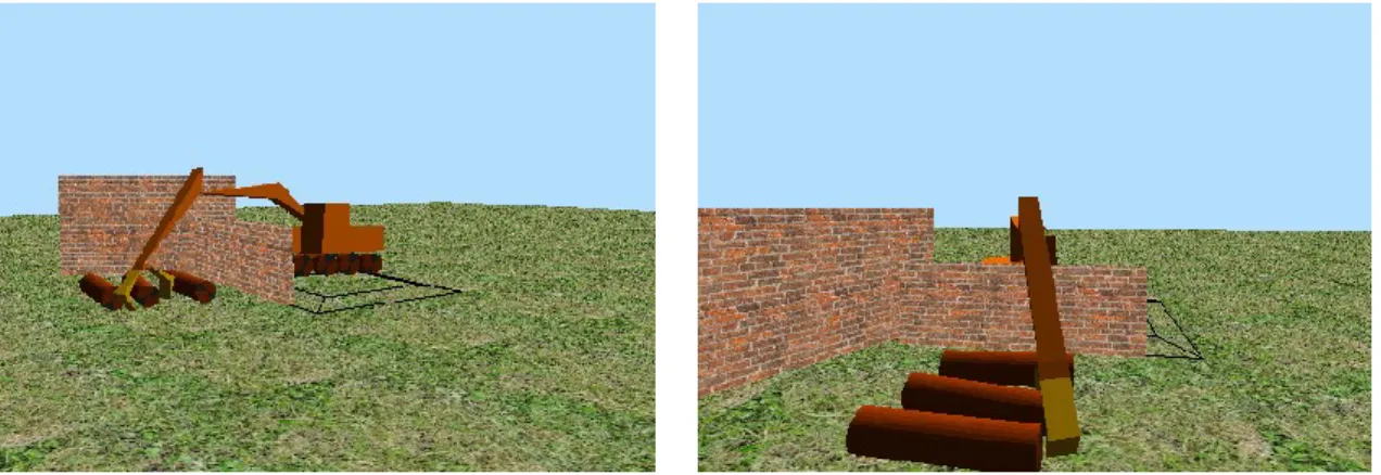
Unmanned construction machine is not only be used on plains, but also be used on complicated terrains such as in mountain area [18]. In such complicated cases, the atti- tude difference can be very big and maybe there are some steep slope like cliff. Attitude everywhere is different. Compared with such cases, there is almost no attitude differ- ence is relatively small. However, in some cases, objects are put on different height above the same attitude. Thus, it is almost impossible for us to treat required observa- tion areas like that in 2D cases [19], [20]. Meanwhile, cameras should be also put on different height above local attitude to meet different televising demand (Figure 2.1).
Until now, camera placement in complicated terrain is always conducted by experience.
Therefore, sometimes blind angle appears which makes efficiency in unmanned con- struction case much lower than that in manned construction case [14], [15]. So more observable area are required to solve the problem, and it can be better done by computer instead of human being’s experience.
Figure 2.1 Different camera televising demand
2.2 Related works
In traditional method, observation targets and line-of-sight-based sensors such as cam- eras are always treated as points putting on a planar surface, which makes sensing range treated as a planer sector [19], [20]. It can be only used in 2D environment (Figure 2.2 (a)). Compared with this, there exists another improved method, through which obser- vation targets and cameras can be put on non-planar surface [21]. Therefore, the sensing range of a camera becomes a cone instead of a sector. By using this method, it is possi- ble to conduct camera arrangement on complicated terrain if height above local attitude is fixed. It is a pseudo-3D method (Figure 2.2 (b)). However, both of them cannot meet the requirement of unmanned construction, so I decided to make a novel line-of-sight- based model to enable observation targets and cameras put on variable height on com- plicated terrain to realize 3D camera placement (Figure 2.2 (c)).
Figure 2.2 line-of-sight-based sensor model Overlook
Detail
(a) (b) (c)
2.3 Proposed model
2.3.1 Camera model
In order to simplify the camera model in 3D environment, the volume of camera is ig- nored as the models in 2D or pseudo-3D environment [19], [20], [21]. Thus we can treat our cameras in 3D model as a particle. Besides, it should own the following properties.
Basic properties of a 3D object o Position
o Orientation
Perspective
o Angle of view o Aspect ratio o Sensing distance o Up direction 2.3.1.1 Basic properties
In traditional 2D models, the position is always defined as (1).
𝑝 = (𝑥, 𝑦) (1)
In pseudo-3D models, it is described as (2), where z is defined in (3) [21].
𝑝 = (𝑥, 𝑦, 𝑧) (2)
𝑧 = 𝑔(𝑥, 𝑦) (3)
Here, z is the height above local position corresponding to x and y, which means that height of camera is not variable when x and y are fixed. In order to make it variable, height of camera above local position should be introduced. Thus I modify function g and rewrite it as (4).
𝑧 = 𝑔(𝑥, 𝑦) + ℎ (4)
h means the height of camera above the local ground, which enables it to be positioned in different height at the same position.
The orientation of camera includes the yaw angle θ around the vertical axis and pitch angle ξ around the horizontal axis. Therefore, the property of camera i can be described as (5).
𝑐𝑖 = (𝑝𝑖, 𝜃𝑖, 𝜉𝑖) (5) Thus, the basic property ci of camera i in my novel 3D model is like Figure 2.3.
Figure 2.3 Basic property 𝒄𝒊 of camera 𝒊 2.3.1.2 Perspective
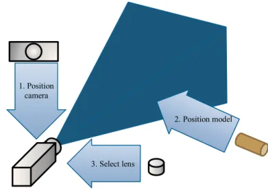
The common process for taking a photograph of a desired view with a camera is shown in Figure 2.4.
Figure 2.4 Steps in configuring and positioning the viewing frustum 𝜃𝑖 𝜉𝑖
(𝑥𝑖, 𝑦𝑖, 𝑔(𝑥𝑖, 𝑦𝑖) + ℎ)
(𝑥𝑖, 𝑦𝑖, 𝑔(𝑥𝑖, 𝑦𝑖)) y
ylocal
xlocal
o
x ci
1. Position camera
3. Select lens
2. Position model
The position and orientation of camera is not only decided according to those of object, but also decided by lens selected. As shown in Figure 2.5, when cameras with different perspective properties produce the desired view, position of cameras are different. In Figure 2.6, four factors of perspective is defined. Volume, shape of it, direction of view are decided by these four factors.
Figure 2.5 Different perspective properties in 2D view
Figure 2.6 Perspective of a camera
Commonly, sensing distance is related to the resolution, the higher the bigger. It totally depends on the development of hardware. Aspect ratio depends on the properties of hardware as well. Here, we set the distance as 30 meters and aspect ratio as traditional 4:3. Up direction is always set as the reverse direction of gravity, which meets human habits. Moreover, angle of view depends on the requirement of tasks. In unmanned con- struction case, wide-angle lenses, standard lenses and long focus lenses are commonly
Angle of view
Sensing distance
Up direction
Sensing distance Width
Height
Angle of view
Up direction
Aspect ratio = 𝑊𝑖𝑑𝑡ℎ 𝐻𝑒𝑖𝑔ℎ𝑡
used [18]. Since telephoto lens sub-type are usually used instead of long focus lenses, they are referred to parlance as “medium telephoto lenses” and “super telephoto lenses”
[24]. The previous one is widely used. Each angle of view is as follows [25].
Wide-angle lenses: 64°~114°
Standard lenses: 40°~62°
Medium telephoto lenses: 10°~30°
These angles of view are always diagonal angles. They should be transformed to verti- cal ones to be used in computer graphics. After transformation, they become as follows.
Wide-angle lenses: 41°~85°
Standard lenses: 25°~40°
Medium telephoto lenses: 6°~18°
In order to avoid the distortion of wide-angle lenses and simplify the computation, mul- tifunctional lenses are used. The vertical angle of view is defined from 10°~70°.
2.3.1.3 Coverage
After deciding the basic properties and perspective, the coverage area of camera ci can be determined. The coverage judgment of camera ci observing point q can be described as a Boolean function (6).
𝐶𝑜𝑣(𝑐𝑖, 𝑞) (6)
The Boolean value is corresponding to the distance between camera ci and point q, pan angle and tilt angle between ci and q and visibility from pi to q. They are written in (7~10)
𝑑(𝑐𝑖, 𝑞) = ‖𝑝𝑖 − 𝑞‖ (7)
𝑝(𝑐𝑖, 𝑞) = atan2((𝑦𝑞− 𝑦𝑝𝑖) (𝑥⁄ 𝑞− 𝑥𝑝𝑖)) − 𝜃𝑖 (8) 𝑡(𝑐𝑖, 𝑞) = atan((𝑧𝑞− 𝑧𝑝𝑖) ‖𝑝⁄ 𝑖− 𝑞‖) − 𝜉𝑖 (9)
𝑣(𝑐𝑖, 𝑞) ∈ {0,1} (10)
In (10), 0 stands for invisible and 1 stands for visible. Visibility judgment is shown in Figure 2.7.
Figure 2.7 Visibility of target from camera Thus, function (6) can be written as equation (11)
𝐶𝑜𝑣(𝑐𝑖, 𝑞) = 𝑓[𝜇𝑑(𝑐𝑖, 𝑞), 𝜇𝑝(𝑐𝑖, 𝑞), 𝜇𝑡(𝑐𝑖, 𝑞), 𝑣(𝑐𝑖, 𝑞)] (11) According to the sensing distance, angle of view in pan plane and that in tilt plan, μd, μp, μt are defined as Boolean function. 1 stands for meeting the demand and 0 stands for not meeting the demand. Then, (11) can be represented as the product of μd, μp, μt and v in equation (12).
𝐶𝑜𝑣(𝑐𝑖, 𝑞) = 𝜇𝑑(𝑐𝑖, 𝑞) ⋅ 𝜇𝑝(𝑐𝑖, 𝑞) ⋅ 𝜇𝑡(𝑐𝑖, 𝑞) ⋅ 𝑣(𝑐𝑖, 𝑞) (12)
2.3.2 Target model
Observation targets are always treated as points with no volume [22]-[24]. Their posi- tions are set above the local attitude, which is similar to that of cameras. We set the po- sition of target qi as (13), where z is defined in (14). Here, h depends on the height above ground.
𝑞𝑖 = (𝑥, 𝑦, 𝑧) (13)
𝑧 = 𝑔(𝑥, 𝑦) + ℎ (14)
2.3.3 Environment model
In order to make the model adapt to most cases with variant complexity, the terrain is treated as a surface and described as (15). Here, z is described (16) and means the atti- tude of local position.
𝑡 = (𝑥, 𝑦, 𝑧) (15)
Visible
Invisible
Camera
Target
𝑧 = 𝑔(𝑥, 𝑦) (16) Because the carrier of a camera is a vehicle, the area covered cannot be ignored. There- fore, I divide the terrain into (a-1)(b-1) meshes averagely, where a stands for the num- ber of rows and b stands for the number of columns. Each mesh is a little bigger than the covered area of carrier. These camera carriers are set at the center of meshes respec- tively. Each mesh can only set one carrier. In some cases, camera carriers are perhaps not stable on the local meshes, so tilt and smoothness of each mesh have to be taken in- to consideration.
Four vertexes of each mesh are rarely on the same plane only if the mesh is completely flat. In order to calculate the tilt and smoothness, all meshes are all treated as tetrahe- drons.
In my proposed model, smoothness depends on the distance ‖ℎ⃗ ‖ between two diagonals 𝑣1
⃗⃗⃗⃗ and 𝑣⃗⃗⃗⃗ , which are bolded in Figure 2.8 (a). Tilt depends on the angle 2 τ between the green plane and black plane in Figure 2.8 (b). The green plane here should parallel to the two bolded diagonals.
Figure 2.8 Smoothness and tilt of a mesh
The direction of unit normal vector 𝑛⃗⃗⃗⃗⃗⃗⃗⃗⃗⃗⃗⃗ of the black plane is the reverse direction of 𝑏𝑙𝑎𝑐𝑘 gravity, thus it can be written as (17). Thus, the tilt and smoothness of the mesh can be measured by (17~20), where 𝑛⃗⃗⃗⃗⃗⃗⃗⃗⃗⃗⃗⃗ stands for the unit normal vector of the green plane. 𝑔𝑟𝑒𝑒𝑛
𝑛𝑏𝑙𝑎𝑐𝑘
⃗⃗⃗⃗⃗⃗⃗⃗⃗⃗⃗⃗ = (0, 0, 1) (17) 𝑛⃗ 𝑔𝑟𝑒𝑒𝑛 = (𝑣 1× 𝑣 2) (‖𝑣 ⁄ 1‖ ⋅ ‖𝑣 2‖) (18) ℎ⃗
𝑣2
⃗⃗⃗⃗
𝑣1
⃗⃗⃗⃗
𝑛𝑏𝑙𝑎𝑐𝑘
⃗⃗⃗⃗⃗⃗⃗⃗⃗⃗⃗⃗ 𝜏 𝑛⃗⃗⃗⃗⃗⃗⃗⃗⃗⃗⃗⃗ 𝑔𝑟𝑒𝑒𝑛
(a) (b)
‖ℎ⃗ ‖ = |𝑛⃗ 𝑔𝑟𝑒𝑒𝑛⋅ ℎ⃗ | (19) 𝜏 = acos(𝑛⃗ 𝑔𝑟𝑒𝑒𝑛⋅ 𝑛⃗ 𝑏𝑙𝑎𝑐𝑘) (20) When four vertexes are almost on the same plane ‖ℎ⃗ ‖ can be small, which means the mesh is smooth. In this case, the tilt angle between the plane and the ground plane will be calculated. Large τ stands for large tilt angle; large 𝑑 stands for low smoothness. It is possible to position a camera carrier on the center of the mesh only if both ‖ℎ⃗ ‖ and τ are small.
2.4 Evaluation method
The coverage possibility of a single required observation target q by camera ci can be described as (12). Therefore, the coverage possibility of a single required observation target by all cameras can be written as follows:
𝐶𝑜𝑣(𝐶, 𝑞) = 1 − ∏𝑖=1,⋯,𝑛(1 − 𝐶𝑜𝑣(𝑐𝑖, 𝑞)) (21) Here, C stands for the set of all possible cameras and 𝑛 stands for the number of all candidate cameras. In traditional method, the position of cameras is not limited, so all targets can be observed if there are enough cameras. However, in the cases with limita- tion, some targets are maybe not observed by all cameras. Therefore, we propose the following equations to evaluate the coverage rate more precisely.
𝑁𝑜𝑏𝑠𝑒𝑟𝑣𝑎𝑏𝑙𝑒 = ∑𝑖=1,⋯,𝑚𝐶𝑜𝑣(𝐶, 𝑞𝑖). (22) 𝑁𝑜𝑏𝑠𝑒𝑟𝑣𝑒𝑑 = ∑𝑖=1,⋯,𝑚𝐶𝑜𝑣(𝑁, 𝑞𝑖). (23) 𝐶𝑂 = 𝑁𝑜𝑏𝑠𝑒𝑟𝑣𝑒𝑑⁄𝑁𝑜𝑏𝑠𝑒𝑟𝑣𝑎𝑏𝑙𝑒 (24)
𝐷 = 𝑁𝑜𝑏𝑠𝑒𝑟𝑣𝑎𝑏𝑙𝑒⁄𝑚 (25)
N is the set of all used cameras; m stands for the number of observation targets required;
Nobservable means the number of total observable targets; Nobserved means the number of observed targets by used cameras. The rate CO of the observed targets in observable ones is used to evaluate the coverage rate. Meanwhile, the rate D of the observable tar- gets in required ones can describe the complexity of environment observation
2.5 Optimization Strategy of Camera Placement
According to our proposed models, there are more limitation for camera placement. Al- so, camera placement computation and evaluation standard are extended to 3D space.
We cannot thus simplify the environment as a narrow flat plane or a terrain surface as before. Traditional methods like iteration depend on initial values too much, making simulation difficult to find an optimal or suboptimal solution. To solve the problem and verify the feasibility of our proposed models, we make some assumption to simplify the computation for our case.
2.5.1 Preparation
In order to reduce the amount of computation in camera placement, we calculate the possible configuration of each camera in advance. Each possible camera configuration should cover at least 1 required target point, or it is unacceptable. For each camera ci, we have the equation as follows:
𝑡𝑖 = ∑𝑗=1,⋯𝑚𝐶𝑜𝑣(𝑐𝑖, 𝑞𝑗). (26) Here, ti means the number of observable targets by camera ci. If ti is larger than 0, each q, which makes 𝐶𝑜𝑣(𝑠𝑖, 𝑞) = 1, will be stored in set Ti, which is described like:
𝑇𝑖 = {𝑞1, ⋯ 𝑞𝑡𝑖} (27) Here, q1 to qti are all observable targets from camera ci. Considering each camera should shoot required target in its center area, if all measured targets are compressed, we can treat the possible orientation of the camera as the vector from a camera to a required ob- servation target, to simplify the computation by avoiding probable unacceptable proper- ty. Therefore, the total observed targets can be described as the union T of Ti
𝑇 = ⋃𝑖∈𝑁𝑇𝑖 (28)
2.5.2 Proposed placement strategy
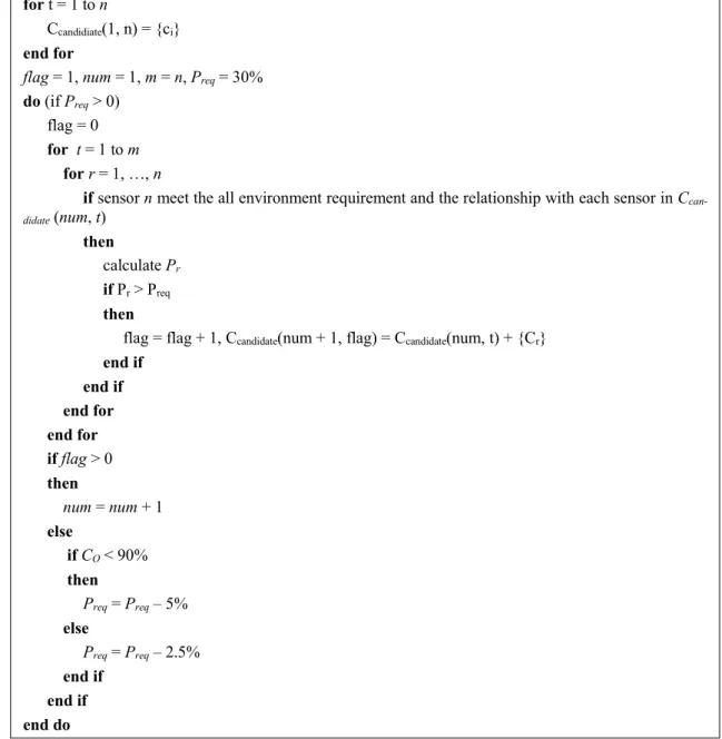
From the analysis of disadvantages of traditional strategies, we propose a practical cam- era placement strategy. The algorithm of the proposed strategy is shown in Fig. 4. In the pseudo-code of camera placement, num stands for the number of cameras used; flag stands for the number of patterns when the number of cameras is decided.
Figure 2.9 Pseudo-code of camera placement in our strategy 2.5.2.1 Traditional strategy
In traditional method, iteration is always used with no practical limitation, which makes the result undependable. There are two main disadvantages [25][30]. First, the initial property of some cameras is not dependable. In some cases, some cameras are still used even if it can hardly observe any required targets. This phenomenon always occurs in large maps with a lot of large valueless observation areas. Random initial values proba- bly set some cameras in such areas, which causes that these cameras have no chance to exchange with better options. Second, the initial number of cameras are always deter- mined by the size of maps. Such iteration methods are always used in the situation where all targets are required to be observed. Random initial cameras are thus nearly
for t = 1 to n
Ccandidiate(1, n) = {ci} end for
flag = 1, num = 1, m = n, Preq = 30%
do (if Preq > 0) flag = 0 for t = 1 to m for r = 1, …, n
if sensor n meet the all environment requirement and the relationship with each sensor in Ccan- didate (num, t)
then
calculate Pr
if Pr > Preq
then
flag = flag + 1, Ccandidate(num + 1, flag) = Ccandidate(num, t) + {Cr} end if
end if end for end for if flag > 0 then
num = num + 1 else
if CO < 90%
then
Preq = Preq – 5%
else
Preq = Preq – 2.5%
end if end if end do
homogeneously distributed in the scene. However, in many practical cases, not all of the targets should be observed and cameras cannot be placed in some areas. Therefore, the initial cameras should depend on the scene and the result should reflect the requirement.
Besides, some other practical requirements should be concerned, such as the safe dis- tance between camera and nearest target, the required distance between each two cam- eras, the landform and etc. We thus try to propose a strategy to obtain the optimal placement of cameras. And, it should adapt to most cases mentioned above.
2.5.2.2 Proposed strategy
In our proposed strategy, the objective should take two things into consideration, the coverage rate and the profit when increasing a new camera. The definition of coverage rate is already mentioned in the previous section. We here set the target coverage rate CO 90% to ensure a high observability. The profit means the rate of value of increased targets and the total value of observable targets when a new camera ci is placed in the scene. The profit Pi is given by (29)
{
𝑃𝑖 = ∑𝑗=1,⋯,𝑛1(𝑞𝑗𝑤𝑗)⁄∑𝑘=1,⋯,𝑛2(𝑞𝑘𝑤𝑘). 𝑞𝑗 ∈ 𝑇𝑖
𝑞𝑗 ∉ 𝑇
(29)
The wi means the value of required target qj, which always concerns the importance of qj. qj belongs to the Ti of increased camera ci and not belongs to the current T which is not refreshed by increasing Ti. n1 stands for the number of such targets qj; n2 stands for the number of total observable targets in the scene. In our research, we set the value of each target 1, so the profit Pi equals to the increased coverage rate. We define the ac- ceptable profit Pr as 30% initially to ensure the cameras which can observe more targets have high computational priority as well as reduce the computational cost. If Pi is larger than Pr, the increased camera i is acceptable. If such Pr does not exist and CO is less than 90%, the coverage lower limit used in our experience, required Pr will reduce 5 percentage points until it becomes 0. If CO is more than 90%, Pr will reduce 2.5 per- centage points until it becomes 0. The Ccandidate with the largest value will be outputted as the optimal result.
2.6 Experiment
2.6.1 Camera carrier and Camera
Considering the property of camera carrier, one carrier can only carry one camera. Ad- ditionally, carrier and the camera carried is on the line which is parallel to the gravity, which means the position of carrier and camera can be written in the equations (30~31).
𝑃𝑣𝑒ℎ𝑖𝑐𝑙𝑒 = (𝑥, 𝑦, 𝑔(𝑥, 𝑦)) (30)
𝑃𝑠𝑒𝑛𝑠𝑜𝑟 = (𝑥, 𝑦, 𝑔(𝑥, 𝑦) + 𝑧𝑟) (31) Because carriers here are all vehicles. Positions of these carriers should be different, which makes arbitrary two cameras are not on the same line parallel to the gravity. Be- sides, they should not be positioned at the same place as required target. Considering the size of camera can be ignored compared with environment size, all cameras are de- fined invisible this time. Assuming the meaningful distance above the ground is 0 to 6 meters and the interval of two targets on the same vertical line is 1 meter, the position of observable target qi can be written as (13~14). Here, x, y and h are non-negative integers.
In addition, 𝑧 ∈ [0,6]. In order to observe such targets and simplify the computation, the interval of two neighbor possible position of one camera on the same vertical line is 1 meter, and the range of the vertical position of each camera is 3 to 9 meters. The posi- tion equation of the camera ci should be (2, 4). And x, y, h are all non-negative integers and ℎ ∈ [3,9].
2.6.2 Environment and Required Targets
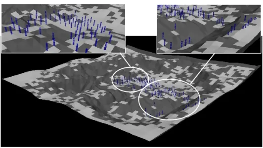
We create a terrain map to verify the feasibility of our proposed practical placement strategy (Figure 2.10).
Figure 2.10 Terrain generated.