(DLC)
Study of Wear Behavior of Nitrogenated Diamond- like Carbon (DLC) Films
through Friction Energy Analysis
2015 3
Shuji YAMAMOTO
(DLC)
Study of Wear Behavior of Nitrogenated Diamond- like Carbon (DLC) Films
through Friction Energy Analysis
2015 3
1 6
1.1 7
1.2 9
1.3 10
1 12
2 DLC 13
2.1 14
2.2 DLC 16
2.3 DLC 18
2.3.1 18
2.3.2 18
2.3.3 18
2.3.4 19
2.3.5 (PLD) 19
2.3.6 PCVD 20
2.4 DLC 21
2.4.1 21
2.4.2 21
2.4.3 21
2.4.4 22
2.4.5 22
2.4.6 22
2.5 DLC 24
2.6 DLC 26
2.6.1 DLC 26
2.6.1.1 DLC 26
2.6.1.2 DLC 28
2.6.2 29
2.6.2.1 DLC 29
2.6.2.2 DLC 30
2.6.2.3 DLC 32
2.6.2.4 DLC 35
2.6.3.1 DLC 36
2.6.3.2 DLC 36
2.6.3.3 DLC 43
2.6.3.4 DLC 45
2.7 46
2.8 51
2 52
3 56
3.1 57
3.2 58
3.2.1 61
3.2.2 63
3.2.3 66
3.3 67
3.3.1 67
3.3.2 69
3.3.3 70
3.3.4 75
3.4 78
3.4.1 78
3.4.2 DLC 80
3.4.3 80
3.4.4 DLC 82
3.5 84
3 85
4 DLC 87
4.1 88
4.2 89
a) DLC DLC 93
b) DLC DLC 95
c) DLC DLC 99
4.2.2.2 SUJ2 SUS440C 101
a) SUJ2 SUS440C 101
b) SUJ2 SUS440C 104
4.2.3 105
4.2.3.1 DLC DLC 105
4.2.3.2 105
4.2.3.3 SUJ2 SUS440C 108
4.2.4 110
4.3 111
4.3.1 111
4.3.1.1 111
4.3.1.2 116
4.3.1.3 117
4.3.1.4 120
4.3.2 121
4.3.2.1 121
4.3.2.2 121
4.3.3 123
4.4 124
4.5 126
4.6 127
4.7 128
4.7.1 Archard 128
4.7.2 130
4.7.3 132
4.7.3.1 132
4.7.3.2 133
4.7.3.3 134
4.7.4 135
4.7.4.1 135
4.7.4.2 ANSYS 136
a) 136
4.7.5 139
4.7.5.1 139
4.7.5.2 ANSYS 140
4.7.6 150
4.7.7 155
4.8 156
4 157
5 DLC 159
5.1 160
5.2 161
5.3 161
5.3.1 161
5.3.2 DLC 161
5.3.3 162
5.3.4 163
5.3.5 165
5.4 168
5.4.1 168
5.4.2 169
5.4.3 SUJ2 SUS440C 173
5.4.4 179
5.4.5 EDS 180
5.4.6 181
5.5 185
5 186
6 DLC DLC 187
6.1 188
6.2 189
6.3.1.3 192
a) 192
b) 192
6.3.1.4 195
6.3.1.5 DLC 198
6.3.2 199
6.3.2.1 199
6.3.2.2 200
6.3.3 201
6.4 DLC 202
6.4.1 202
6.4.2 202
6.4.2.1 DLC 202
6.4.2.2 203
6.4.3 203
6.4.3.1 203
6.4.3.2 203
6.4.3.3 203
6.4.4 207
6.4.4.1 207
6.4.4.2 DLC 207
6.4.4.3 208
6.4.5 210
6.5 211
6 212
7 214
218
219
223
1. 1
2
(1)
(2) FSW(3)(Friction Stair Welding)
GDP
3% (4)
NOx, SOx
95%
(5) %
(DLC) (6) CNT DLC
DLC 0.1
DLC
400 DLC
(7) DLC 400
DLC
1. 2
DLC
DLC DLC
1)
2) 3) 4) 5)
SUJ2
SUS440C DLC DLC DLC
DLC DLC
DLC
(C6H6) DLC
DLC DLC
DLC
1. 3
1 7
1
2 DLC
3
4 DLC
5 DLC
6 DLC DLC
7
1
DLC DLC
2 DLC DLC
DLC
DLC DLC
DLC DLC
EPMA XRD XPS
DLC AFM DLC
3
Holm-Archard
Holm-Archard
ANSYS
5 DLC 3
SUJ2 SUS440C
DLC 4
6 DLC DLC
DLC DLC
DLC 7
1
(1) H. Blok, The flash temperature concept, Wear, Vol.6, (1963), pp.483-455
(2)
K.B. Bonderup, D. Benning, P.K. Kristensen, V.P. Popok, K.Pedersen, Interface structure and strength of ultrasonically wedge bonded heavy aluminum wires in Si- based power modules, J. Mater. Sci.: Mater. Electron, Vol. 25, (2014), pp.2863-2871
(3)
J.M. Rice, S. Mandal, A.A. Elmustafa, Microstructural investigation of donor material experiments in friction stir welding, Int.J. Mater. Form. Vol. 7, (2014), pp.127-137
(4)
24 8 7 pp.28
(5)
D. Majcherczak, P. Dufrenoy and Y. Berthier, Tribological, thermal and mechanical coupling aspects of the dry sliding contact, Tribol. Int., Vol. 40, (2007), pp.834-843 (6) J. Robertson, Diamond-like amorphous carbon, Materials Science and Engineering
R 37, (2002), pp.129-281
(7) L. Wang, X. Nie and X. Hu, Effect of thermal annealing on tribological and corrosion
properties of DLC coatings, Journal of Materials Engineering and Performance,
Vol.22, (2013), pp.3093-3100
DLC
2. 1
DLC
(1)
DLC
DLC 2
sp3
1 DLC sp3 DLC
sp3
DLC 2
DLC
a-C:H CVD
PCVD (CH4) (C2H2)
(C6H6)(2) Erdemir (3) H/C
CVD DLC
H/C
DLC
sp3 (4)
sp3
MSIB (5) FCVA (6)
2 DLC
Ti, Si, F
(7)(8) DLC DLC -C3N4
N2/Ar (N/C) 40%
(9)
DC-RF-PECVD N/C
50% (10) -C3N4
(2) DLC sp3/sp2
DLC DLC
(20)
(21)~(23) DLC
DLC DLC
DLC DLC
3 DLC
CVD
6 DLC
DLC DLC
(C6H6) DLC DLC
3 DLC DLC
sp3 sp2
X XPS X
DLC DLC
2. 2 DLC
2.1 sp3, sp2, sp1 3
sp3
4 4 sp3
5.5 eV
sp2 4 3 3
4 1
0
C60
sp1 4 2 x 2
y z (4)
DLC sp2 sp3
DLC
(MEMs)
2.1 DLC
(1)
2.2 sp3 sp2 (24) sp3
(CH2)n (CH)n
sp3 a-C (tetrahedral) (ta-
Fig. 2.1 Bonding configurations of carbon sp3, sp2, sp1structure.
Table 2.1 Comparison of major properties for DLC film, diamond and graphite(3)
Properties DLC film Diamond Graphite
Density (g/cm3) 1.0 3.0 3.51 2.25
Resistance ( cm) 109~ 1011 1016 10-7 Thermal conductivity
(W/m K) 0.2 6 20 0.4 2.1
Lattice parameter (nm) a=0.3567 a=0.2456
c=0,6708 Young s modulus (GPa) 200 800 1150
Vickers hardness (kgf/mm2) 1000 4000 10000
Fig. 2.2 Ternary diagram of bonding in amorphous carbon-hydrogen alloys(24). a-C:H
2. 3 DLC
DLC Aisenberg Charbot(25)
100eV
sp3 CVD
sp3 DLC 100eV
2. 3. 1 (26)
Kaufman
2. 3. 2 (27)
(MSIB) 1 ~ 10 V
5 ~ 40 kV e/m
10-8torr ta-C
MSIB
0.001Å/s
2. 3. 3 (28)
DLC
a-C:H Ar
a-CNx -
Ar 2
sp3 (IBAD)
DLC
2. 3. 4 (29)
1013 cm3
1~10 m 106-108 A /cm
30 % 100 %
ta-C FCVA(filtered cathodic vacuum arc)
1 nm/s
2. 3. 5 (PLD)(30)
ArF
MSIB
MSIB FCVA ta-C
PLD
2. 3. 6 PCVD(31)
rf-PCVD rf
rf
rf
sp3
rf
DLC
50 mTorr 10 %
DLC DLC rf -PCDV
2. 4 DLC
DLC
2. 4. 1 (32)
DLC-Si DLC
DLC (Glycerol-mono-oleate)
2. 4. 2
DLC DLC
(33) SUS
DLC
(34)
DLC
2. 4. 3
2.2 DLC DLC
CD DVD
DLC (35)
(36)
2. 4. 4
DLC (37)
VTR DLC
2. 4. 5
DLC PET
(38) DLC
DLC
2. 4. 6 DLC
2.3 DLC
Table 2.2 DLC films applications for machining tools.
Machining Work materials Applications
Bending aluminum, solder plating, phosphor bronze
lead frame, terminal
Spinning aluminum aluminum can, spray can
Drawing aluminum, cupper photo conductive drum, radiator pipe
Deep drawing aluminum aluminum case
Shearing aluminum, phosphor bronze, silver-cupper-nickel alloy
stencil, parts, contact materials
Powder metallurgy alumina, ferrite, super hard alloy
ceramics throwaway chips
Molding glass, plastics aspheric lens CD DVD
Fig 2.3 DLC films application map
2. 5 DLC (39)
DLC DLC
VDI2840 (40) NEDO DLC
DLC
(1) X XRR: X-ray reflection
(2) ERDA: Elastic Recoil Detection Analysis
(3) sp3/sp2 X XPS: X-ray Photoelectron Spectroscopy
X NEXAFS: Near Edge X-ray Absorption Fine Structure
(4) EPMA: Electron Probe Micro Analyzer
X EDX: Energy Dispersive X-ray spectrometry GDOES: Glow Discharge Optical Emission Spectroscopy
Raman spectrometry (5)
(6) (7) (8) (9) (10) (11)
2.3 2012 sp3/sp2
DLC Type IV
Table 2.3 Classification of DLC films into five categories Type Name sp3/(sp2+ sp3) % Hydrogen content
(atom, %)
Remarks
I ta-C 50 =< sp3=< 90 H =< 5 A type of DLC II ta-C:H 50 =< sp3=< 100 5 < H < 50 A type of DLC III a-C
20 < sp3< 50 H =< 5 A type of DLC
IV a-C:H 5 < H < 50 A type of DLC
V 0 =< sp3=< 20 ( 0 =< H =< 5) Other film I Graphite-like
VI ( 50 =< H =< 70) Other film II
5 =< H @ sp3<20 Polymer-like
2. 6 DLC
2. 6. 1 DLC
2. 6. 1. 1 DLC
DLC (C6H6) PCVD
rf-PCVD(radio frequency plasma chemical vapor deposition) 2.4
(MAV-R2) RF
2.5 2.4 PCVD
(WC-9 wt.% Co JIS V30 ) 10
XPS 1 2
DLC 2.6
3 10-3 Pa
0.05 Pa RF 13.56 MHz RF 0.25 kW
5
C-Si HMDSO hexamethyldisiloxane C6H18OSi2
0.3 Pa RF 0.5 kW 2
(C6H6)
15 sccm (standard[25 , 1 atm] cc/minute) RF 0.5 kW
50 60
Table 2.4 Equipment configurations of rf-PCVD.
Equipment RF generator Power source Vacuum system Turbo molecular pump
Manufacture Machining Network
JEOL KASHIYAMA Osaka vacuum
Model EH-MN03A JRF-3000 KRS-1301 TG800FVWP
Fig. 2.4 Apparatus of rf-PCVD prepared for DLC films
Fig. 2.5 Schematic diagram of the rf-PCVD deposition equipment
Fig. 2.6 Inside of rf-PCVD chamber (left side) and the specimens mounted on the work holder (right side)
2. 6. 1. 2 DLC
DLC NDLC 15 sccm
(C6H6) 99.99 % 0.3 Pa RF
0.5 kW 50 60 HMDSO
DLC DLC
N2/(C6H6+ N2) 0.66( 30sccm) 0.8( 60sccm) 0.87( 100sccm)
3 DLC
2. 6. 2
2. 6. 2. 1 DLC
DLC EPMA (Electron Probe Micro Analyzer
X JXA-8100) EDS (Energy
Dispersive X-ray Spectrometry X ) EDS
X Li Si
EDS
EPMA X
EDS
2.5
Table 2.5 Measurement conditions of EPMA and EDS
Detector Model Voltage Current
EPMA JXA-8100 10 kV 50 nA
EDS JEOL EX-2300 15 kV 2.6 nA
2. 6. 2. 2 DLC
X DLC ( RITN-UltimaIII)
40 kV/40 mA 0.2
mm 2 2 10 ~ 90 0.052
400 ~ 4000 cm-1
1584 cm-1
G (defect) D
1350 cm-1 1333 cm-1
(41)
Reinshaw inVia Reflex
532 nm D G
D G D G
Lorentzian (42) D G
sp3,
sp2, 2.7 100 sccm
DLC
D band peak G band peak
C N bond peak
Raman shift/cm-1
XPS (X-ray Photoelectron Spectroscopy, EOL JPS-9010TR) X
(
) X h
EB
XPS
nm
10-8Pa
90 Cu 2P3/2
( 932.67 eV Au 4f7/2( 83.98 eV) C1s
C1s N1s 1 eV
2.8 0 1100 eV
C1s 285 eV N1s 400 eV
0.1 eV 282 ~ 289 eV 395 ~ 403 eV
Fig. 2.8 XPS wide scan data for NDLC film (nitrogen: 100 sccm)
0 2000 4000 6000 8000 10000 12000 14000
0 200 400 600 800 1000
Binding Energy, eV
C 1s
N 1s
2. 6. 2. 3 DLC
DLC DLC
(SM-09010, JEOL) FE-SEM(Field Emission Scanning Electron Microscope, JSM7001F, JEOL)
5 kV, 120 A
DLC
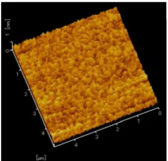
DLC DLC AFM
SII Nanocute
1200 m 8 m 40 N/m 459 kHz 5 m
2.9 100 sccm DLC
AFM
Fig. 2.9 Typical AFM image of NDLC surface prepared from C6H6and nitrogen 100 sccm
1/10
(43) m
0.1 m
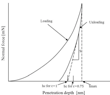
(2.1)
hs hs unload
S
N 0.75
As
f0(hc) (2.1) (2.2) (2.3)
h
Fig. 2.10 Schematic of the cross section of the indenter penetration
Fig. 2.11 Schematic of the normal force versus indenter penetration depth
S
Ef
,
5 mN DLC
(kgf)/ (mm2) (Pa)
gn 9.8 m/s2
HV h
(2.8)
2. 6. 2. 4 DLC
DLC DLC
Hiresta-UP MCP-MT450 URS
+ 6mm, - 11mm DLC
DLC 10
2. 6. 3
2. 6. 3. 1 DLC
2.6 DLC DLC EPMA
30, 60, 100 sccm DLC 5.4, 7.3 10.7 mass%
DLC 5.4, 7.3 10.7
mass% DLC
N5.4DLC, N7.3DLC, N10.7DLC
Table 2.6 Carbon and nitrogen contents in the DLC and NDLC films measured by EPMA
N2sccm N2/(C6H6+ N2) C mass% N mass%
0 0 100 ND
30 0.66 94.7 5.4
60 0.8 91.0 7.3
100 0.87 87.7 10.7
2. 6. 3. 2 DLC
X 2 (002) 26.4°
(111) 43° X DLC
DLC DLC
1350 cm-1 D 1584 cm-1 G
Lorentz 2.12 (a) d)
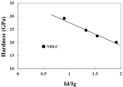
2.7 D G Id/Ig G
Id/Ig DLC
Id/Ig G
Table 2.7 Id/Ig ratios and G band peaks of DLC and NDLC films measured by Raman
Fig. 2.12 (a) Raman spectrum of DLC film on silicon substrate
0 2000 4000 6000 8000
800 1000 1200 1400 1600 1800 2000
Raman Shift cm
-1G band peak
D band peak
N
5.4DLC
Fig. 2.12 (c) Raman spectrum of N7.3DLC film on silicon substrate
1000 2000 3000 4000 5000 6000 7000
G band peak D band peak
N
10.7DLC
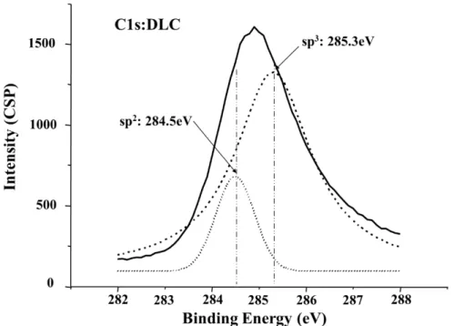
2.13 DLC C1s XPS DLC
DLC XPS (45) Gelius sp3
sp2 285.3 eV 284.5 eV (46)(47)
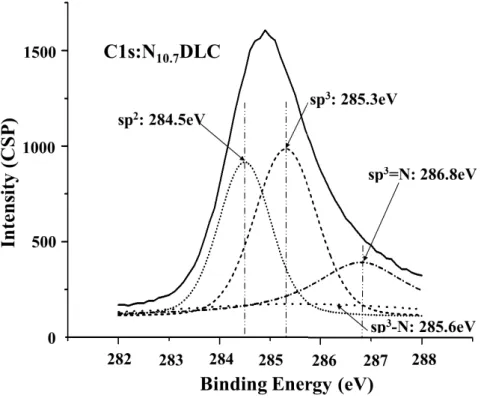
Ronning (48) sp3 1 (sp3-N)
285.6 eV, 2 (sp3=N) 286.8 eV
2.13 Gelius Voigt (49)
DLC Gelius Ronning sp3 sp2 sp3-
N sp3=N Voigt 4
2.14 (a) (b) N7.3DLC N10.7DLC
2.15 C1s DLC N7.3DLC N10.7DLC
C1s
2.8 sp3 sp2
DLC sp2 sp3 sp3-N sp3=N 4 DLC sp3 sp3 sp3-N sp3=N
sp3/sp2 4.5 2.3
Table 2.8 sp3/sp2ratios of DLC and NDLC films XPS DLC N5.4DLC N7.3DLC N10.7DLC
sp3/sp2 4.5 -* 3.1 2.3
*
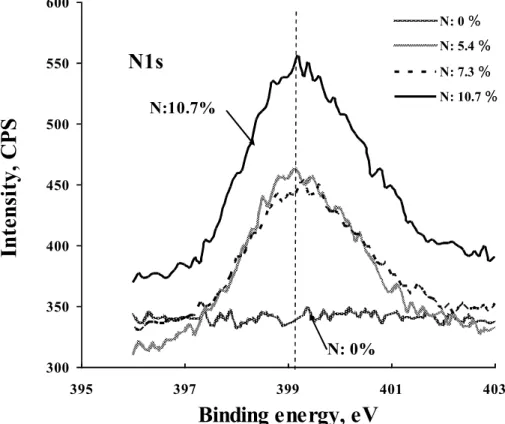
2.16 DLC DLC N1s
DLC N1s DLC
1s DLC N1s
397.3 eV 1s (50)
7.3 mass % 10.7 mass % DLC
399.3eV 399.4eV N1s
N-sp3C (399.7 eV) N-sp2C (400.5 eV)(51) Cyanides C N 398.9 eV(52) C-N
Fig. 2.13 Fitting curves of the sp2structure and sp3structure at C1s: DLC film
Fig. 2.14 (b) Fitting curves of sp3, sp2, sp3-N and sp2=N peaks N10.7DLC film
Fig. 2.16 XPS spectra of N1s of DLC and NDLC films on silicon substrates 300
350 400 450 500 550 600
395 397 399 401 403
Binding energy, eV
N: 0 N: 5.4 N: 7.3 N: 10.7
N1s
N: 0%
N:10.7%
2. 6. 3. 3 DLC
DLC
SEM DLC
2.9
DLC DLC
2.17 DLC 2.18 DLC AFM
2.10 AFM
DLC DLC (Ra)
DLC 0.13 nm DLC 0.12 nm
0.14 nm
2.11 DLC DLC
10 GPa
10% DLC DLC
Table 2.9 Film thickness of each DLC film obtained by back scattering method of FE-SEM
DLC DLC N5.4DLC N7.3DLC N10.7DLC
Thickness ( m) 0.487 0.588 0.903 1.06
Table 2.10 Average surface roughness of each DLC film obtained by AFM measurement
AFM Si
(nm)
DLC (nm)
N5.4DLC (nm)
N7.3DLC (nm)
N10.7DLC (nm) Roughness
(Ra)
0.08 0.13 0.14 0.12 0.14
Silicon substrate DLC
Fig. 2.17 AFM images of the silicon substrate and surfaces of DLC film on silicon substrate
N5.4DLC N7.3DLC N10.7DLC
Fig. 2.18 AFM images of the surfaces of NDLC films on silicon substrates
Table 2.11 Hardness and Young s modulus of DLC and NDLC films obtained by nano- indenter
DLC NH
(GPa)
Standard Deviation
(GPa)
Vickers Hardness (kgf/mm2)
Young s Modulus
(GPa)
DLC 29.2 3.30 2710 263
N5.4DLC 24.7 2.32 2290 221
N7.3DLC 22.5 1.22 2090 193
2. 6. 3. 4 DLC
(sp3) (sp2)
DLC 2.19
DLC 1010 m
7.3 mass 106 m 4
Fig. 2.19 Electrical resistivity of NDLC films as a function of nitrogen content
106 107 108 109 1010 1011
0 2 4 6 8 10 12
Nitrogen content (%)
2. 7
3 ( ) sp3
sp2 sp1
DLC X
sp1 sp3
sp2 XPS
DLC 2.6
100 sccm 0.87 10.7 mass% (3)
(C6H6) DLC
0.95 15 mass%
1584 cm-1
G (defect) D 1350 cm-1
1333 cm-1 DLC
DLC 1500cm-1 G D
DLC
G D
sp2 sp3 sp2
sp2 sp3
50 ~ 30 G (53)
G D 2.7
D G Id/Ig
G 1600 cm-1
Ferrari Robertson(54) DLC 2 nm
DLC 3 Id/Ig G
Id/Ig G
sp2
sp3
Kaufman Metin(41) RF C5H10
DLC FT-IR
sp3 sp2
Ferrari Robertson(54) (CH4 C6H6 C4H10)
a-C:H (DLC) sp3
Id/Ig G sp3
sp3 EELS
Id/Ig 2.21 DLC
Id/Ig
Id/Ig Id/Ig sp3/sp2
XPS DLC sp3- sp2
sp3 sp2
400 eV XPS
2.22 DLC DLC
:10.7 mass% DLC 2200 cm-1
2200 cm-1 C N (55)
DLC
Silva Aamratung(56) FT-IR DLC
XPS DLC
sp3 sp2
Fig. 2.20 Relationship between sp3/sp2ratio of the NDLC films and the hardness
Fig 2.21 Dependence of the Id/Ig of the NDLC films on the hardness
Fig. 2.22 Raman spectra of DLC and N10.7DLC films around 2200 cm-1
DLC DLC 1010 m
7.3 mass% 106 m 4
sp3 sp2
sp3
Amir Kalish(57) DC C6H6
a-C:H:N 10 mass%
1 mass% 5
2 1
2
sp3 sp2
DLC
XPS 2
sp3 sp2
Ferrari Robertoson (54)
a-C:H Id/Ig Id/Ig
sp3
DLC sp3
sp3-sp2-H 2.23
DLC sp3 DLC sp3/sp2
DLC sp3-sp2-H
Fig. 2.23 DLC structure transformation due to nitrogen content
2. 8
DLC DLC
DLC DLC sp3/sp2
XPS,
1) C6H6 CVD DLC
Id/Ig
G peak XPS
sp3/sp2 DLC sp3- sp2
sp3 sp2
2) DLC
DLC C=N C N sp3/sp2
3) 7.3 mass%
1010 106 4
sp3 sp2
DLC DLC
(1) DLC (2006), pp 17-39, NTS
(2) DLC
Vol.4,(2001), pp.23-26
(3) A. Erdemir, O. L. Eryilmaz, I. B. Nilufer, and G. R. Fenske, Effect of source gas chemistry on tribological performance of diamond-like carbon films, Diamond and Related Materials Vol.9, (2000), pp.632-637
(4) J. Robertson, Diamond-like amorphous carbon, Materials Science and Engineering R 37, (2002), pp.129-281
(5) Y. Lifshitz, Hydrogen-free amorphous carbon films: correlation between growth conditions and properties, Diamond and Related Materials Vol.5, (1996), pp. 388- 400
(6) A. Anders, Approaches to rid cathodic arc plasmas of macro- and nanoparticles: a review, Surface and Coatings Technology, Vol.121-123, (1999), pp. 319-330
(7) K. Oguri, T. Arai, Two different low friction mechanizms of diamond-like carbon with silicon coatings formed by plasma-assisited chemical vapor deposition, Journal of Materials Research, Vol.6, (1992), pp.1313-1316
(8) Y. Lin, E. Erdemir, E. I. Meletis, A study of the wear mechanism of diamond-like carbon films, Surface & Coatings Technology, Vol.82 (1996), pp. 48-56
(9) S. Lopez, H. M. Dunlop, M. Benmalek, G. Tourillon, M. S. Wong, W. D. Sproul;, XPS, XANES and ToF-SIMS characterization of reactively magnetron sputtered carbon nitride films, Surf. Interface Analysis, Vol.25, (1997), pp.315-323
(10) J. Hao, T. Xu, W. Liu, Preparation and characterization of hydrogenated carbon nitride films synthesized by dual DC-RF plasma system, Materals Science and Engineering A, Vol.408, (2005), pp.297-302
(11) Y. Taki, N. Yajima, O. Takai, Effects of deposition pressure on structure and hardness of amorphous carbon nitride films synthesized by shielded arc ion plating, Thin Solid Films, Vol.334, (1998), pp.165-172
(12) O. Takai, Y. Taki, T. Kitagawa, Deposition of carbon nitride thin films by arc ion plating, Thin Solid Films, Vol.317, (1998), pp.380-383
(15) K-H. Lee, Y. Inoue, H. Sugimura, O. Takai, Correlation between wear-resistance and chemical structure of CNx films synthesized by shielded arc ion plating, Surface &
Coatings Technology, Vol. 169-170, (2003), pp.336-339
(16) K-H. Lee, H. Sugimura and Y. Inoue, O. Takai, Dependence of hybridizations analyzed by XPS and visible Raman spectroscopy on nanohardness and wear resistance of amorphous carbon and carbon nitride films, Diamond and Related Materials, Vol.13, (2004), pp. 507-512
(17) K-H. Lee, O. Takai, Nanoindentation study on nanomechanical characteristics of a- CN film deposited by shielded arc ion plating, Diamond and Related Materials, Vol.
14, (2005), pp. 1444-1450
(18) K-H. Lee, O. Takai, Nanomechanical properties through nanoindentation method of amorphous carbon and carbon nitride films synthesized by shielded arc ion plating, Surface & Coatings Technology, Vo. 200, (2005), pp.2428-2432
(19) A. Y. Liu, M. L. Cohen, Structural properties and electronic structure of low- compressibility materials: -Si3N4 and hypothetical -C3N4, Physical Review B, Vol.41, (1990), pp.10727-10734
(20) , DLC , , Vol.53, (2002), pp.
715-720
(21) S.Bhattacharyya, Mechanism of high n-type conduction in nitrogen-doped nano crystalline diamond, Phsical Review B, Vol.70, (2004) pp.125412-1~10
(22) S.Bhattacharyya, S.R.P Silva, Transport properties of low-dimensional amorphous carbon films, Thin Solid Films Vol.482, (2005), pp.94-968.
(23) K.Teii, T.Ikeda, Conductive and resistive nanocrystalline diamond films studied by Raman spectroscopy, Diamond and Related Materials, Vol.16, (2007), pp.753-756 (24) W. Jacob, W. Moller, On the structure of thin hydrocarbon films, Surface and
Coatings Technology, Vol.63, (1993), pp.1771-1773
(25) S. Aisenberg, R. Chabot, Ion Beam Deposition of Thin Films of Diamond-like Carbon, Journal of Applied Physics, Vol.42, (1971), pp.2953-2957
(26) R. Locher, C. Wild, P. Koidl, Direct ion-beam deposition of amorphous hydrogenated carbon films, Surface and Coatings Technology, Vol.47, (1991), pp.426-432
(27) H. Hofsass, H. Binder, T. Klumpp, E. Recknagel, Doping and growth of diamond-like carbon films by ion beam deposition, Diamond and Related Materials, Vol.3, (1994), pp. 137-142
(28) M. Rubin, C.B. Hopper, N. H. Cho, B. Bhusahn, Optical and mechanical properties of dc sputtered carbon films, Journal of Materials Research. Vol.5, (1990), pp.2538-
(29) B. F. Coll. M. Chhowalla, Modelization of reaction kinetics of nitrogen and titanium during TiN arc deposition, Surface and Coatings Technology, Vol.68, (1994), pp.131-140
(30) A.A. Voevodin. M.S. Donley, Preparation of amorphous diamond-like carbon by pulsed laser deposition, Surface and Coatings Technology, Vol.828, (1996), pp.199- 213
(31) A. Bubenzer, B. Dischler, G. Brandt, P. Koidl, rf plasma deposited amorphous hydrogenated hard carbon thin films: Preparation, properties, and applications, Journal of Applied Physics, Vol.54, (1983), pp.4590-4595
(32) , DLC , Vol.58, 8, (2013), pp.557-
565
(33) , DLC ,
Vol.42 6, 1997 pp.436-441
(34) DLC 2003
(35) , DLC , Vol.54 1 2009
pp.28-33
(36) , DLC , NACHI-BUSINESS news Vol.1 2003
pp.1-6
(37) , , NEW
DIAMOND 20 Vol.22 2006 pp. 30
(38) ,
DLC , Vol42 1 2005-1 pp.42-43
(39) , DLC , Vol.58,
8 (2013), pp.538-544
(40) VDI 2840 Carbon Films Basic Knowledge, Film Types and Properties, (2005), Verein Deuttscher Ingennieure, Dusseldorf
(41) J. H. Kaufman, S. Metin, Symmetry breaking in nitrogen-doped amorphous carbon:
Infrared observation of the Raman-active G and D bands, Physical Review B, Vol.39, (1989), pp. 13053-13060
(42) D.Roy, M.Chhowalla, N.Hellgren, T.W.Clyne, G.A.J.Amaratunga, Probing carbon
Journal of Materials Research Vol.7, (1992), pp. 1564-1583
(45) A. Crunteanu, M. Charbonnier, M. Romand, F. Vasiliu, D. Pantelica, F. Negoita, R.
Alexandrescu, Synthesis and characterization of carbon nitride thin films obtained by laser induced chemical vapour deposition, Vol.125, (2000), pp.301-307
(46) U.Gelius, P.F.Heden, J.Hedman, B.J.Lindberg, R.Manne, R.Nordberg, C.Nordling, K.Siegbahn, Molecular spectroscopy by means of ESCA III, Carbon compounds, Physica Scripta, Vol.2, (1970), pp.70-80
(47) U.Gelius, C.J.Allan, G.Johansson, H.Siegbahn, D.A.Allison, K.Siegbahn, The ESCA spectra of benzene and iso-electronic series, thiophene, pyrrole and furan, Physica Scripta, 3 (1971) 237-242
(48) C.Ronning, H.Feldermann, R.Merk, H.Hofsass, P.Reinke, J.U.Thiele, Carbon nitride deposited using energetic species: A review on XPS studies, Physical Review B, Vol.58, (1998), pp.2207-2215
(49) ,
, , Vol.60, No1, (2009), pp.48-55 (50) XPS Database ; http://techdb.podzone.net/
(51) T. W. Scharf, R. D. Ott, D. Yang, J. A. Barnard, Structural and tribological characterization of protective amorphous diamond-like carbon and amorphous CNx overcoats for next generation hard disks, Journal of Applied Physics, Vol.85, (1999), pp. 3142-3154
(52) W. Gissler, P. Hammer, J. Haupt, Hardness and elasticity of diamond-like carbon films prepared by ion-beam assisted sputter deposition, Diamond and Related Materials, Vol.3, (1994), pp. 770-774
(53) S.R.Salis, D.J.Gardiner, M.Bowden, J.Savage, D.Rodway, Monitoring the quality of diamond films using Raman spectra excited at 514.5 nm and 633 nm,
Diamond and Related Materials,, Vol.5, (1996), pp.589-591
(54) A. C. Ferrari and J. Robertson, Interpretation of Raman spectra of disordered and amorphous carbon, Physical Review B, Vol.61, (2000), pp.14095-14107
(55) S. E. Rodil, A. C. Ferrari, J. Robertoson, W. I. Milne, Raman and infrared modes of hydrogenated amorphous carbon nitride, Journal of Applied Physics, Vol.89, (2001), pp.5425-5430
(56) S. R. P. Silva, G. A. J. Aamratunga; Doping of rf plasma deposited diamond-like carbon films, Thin Solid Films, Vol.270, (1995), pp.194-199
(57) O. Amir, R. Kalish, Properties of nitrogen doped amorphous hydrogenated carbon films Journal of Applied Physics, Vol.70, (1991), pp.4958-4962
3. 1
=tan Holm-Archard
Holm-Archard MKS
3. 2
15
200 100
4 (1)
1) 2) 3) 4)
Holm(2), Archard(3)
(4)
[ ] /[ ]
(3.1)
7 (5) 1) (adhesive wear)
2) (abrasive wear)
3) (corrosive wear) 4) (fatigue wear)
5) (fretting wear)
6) (impact wear)
7) (welding wear) 1922 Holm(2)
Holm
Bowden and Tabor(6)
Archard, Hirst, Lancaster mild wear, severe wear
18
Archard(3) Holm
Holm Archard Holm-
Archard
Xrushchov(7)~(10) 1965 MIT Rabinowicz(11)
Holm-
Archard mild wear, severe wear,
k
1899 Kirkaldy
1965 Kraghelsky
1977 MIT Suh
(12) Holm, Archard
3. 2. 1 (13)
2 2
3.1
Fig. 3.1 Contact model of asperity pair
D 3
h
60,000 (14)
galling
3.2
Fig. 3.2 Contact state of wear surface for two bodies
FN A
D n A A
n
k*
k*/3 kadh FN x
Holm-Archard
3~4
3. 2. 2 (13)
3.3
Fig. 3.3 Gouging of a material by a rigid cone
FN
h h
rh dx
dV
tan Archard
kadr
3.4
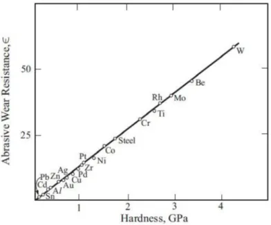
(3.18) 3.5
Fig. 3.4 Change in the wear coefficient with time(15)
Fig. 3.5 Abrasive wear resistance of metallic materials is proportional to the hardness(7)
3. 2. 3
3.4
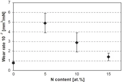
3.6 k
mm3/mN m: N:
Holm-Archard h 1
1 h
Fig. 3.6 Typical wear loss chart: Unit of wear rate as mm3/mN is used(16)
kgf/mm2
Holm-Archard k
3.6 mN m[ ] N[ ]
joule
3. 3
3. 3. 1
(17) (4)
Jahanmir
(18) Kallas
(19)
1930
calorie (20)
95% (21)
700
Mohrbaacher (22)~(24) CVD DLC
DLC Fouvry(25)~(29) Liskiewicz (30)(31)
"dissipated energy"
3.7
(30)
dissipated energy
Fig 3.7 Fretting cycle loop(30)
Ed dissipated energy g
2
"dissipated energy"
dissipated energy
3. 3. 2
Holm-Archard
DLC
Holm-Archard(2)(3) Holm-Archard
(3.20)
3.20 )
k (3.20)
(Input energy)
Aghdam Khonsari(32 Leonald (33) Holm-Archard
S (3.20) S
Holm-Archard P
3. 3. 3
Holm-Archard
(3.22) (3.23)
3.8 FRP-2100
Fig. 3.8 Ball-on-disk apparatus
3.9
N
F =F/N
3.10
Wear Track
N
Load Arm
Fig. 3.10 Friction coefficient sliding distance chart by the ball-on-disk method
l F
l
3.24 3.10
F
3.11
Fig. 3.11 Extended friction coefficient sliding distance chart
3.11
F F N
=F/N
3.11 3.11
3.25 3.10
I 3.25
(3.25) 3.12
3.25
Fig. 3.12 Raw data outputted from tribo-meter
3.10 L
N
=tan
1) :Eh 2) :Ew 3)
:Ee 4) :Ep 5) :Ec
(3.27) (3.28)
1) h 2) w 3) e 4)
° 5) ½
1940 ~ 50 energy
Tim e ( sec) Frictio n force (N) Interval (m ) Fo rce x Interval
0 0 0.01 0
0.1 2.38 0.01 0..0238
0,2 1.54 0.01 0.0154
0.3 2.03 0.01 0.0203
0.4 1.65 0.01 0.0165
499.7 1.24 0.01 0.0124
499.8 1.36 0.01 0.0136
499.9 1.05 0.01 0.0105
500 1.52 0.01 0.0152
Su m 500m En ergy input
Input energy friction energy
Input energy (friction energy) energy
( Input energy, joule) ( Watt,
joule/sec) ( dissipated energy)
3. 3. 4
Ein=
(3.31)
(3.29)
(W)
, Power (W)
V (3.29) h
N
(3.37)
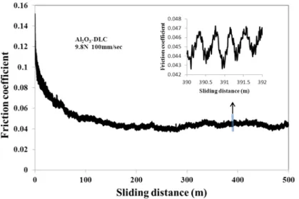
3.13 DLC
100 m =0 (3.38)
3.13
(3.38) / l
dV/dt
Fig. 3.13 Friction coefficient behavior of alumina ball against DLC film
V (3.29) T E
h
(3.30)
(3.40) (3.41)
< 0 > 0
3. 4
DLC 2
DLC DLC 4.8 mm
SUJ2 SUJ2 , SUS440C
SUS440C
SUJ2 DLC SUJ2 DLC SUS440C DLC SUS440C DLC
DLC DLC
3 3 50
30
20 ~ 25 10 ~ 20 %
1 ~ 20 N 25, 50, 75, 100 mm/sec 1000 m
3.3.3
3. 4. 1
3.1 (SUJ2, SUS440C)(10),(11)
SUJ2
SUS440C 200
3.2
100 g 10 SUJ2
SUS440C MIL
GPa
Table 3.1 Elemental composites of SUJ2, SUS440C and alumina balls Ball Material Crystal
Structure
Fe (%)
C (%)
Cr (%)
Ni (%)
Si (%)
Al (%)
O (%)
SUJ2 Carbon
steel
BCC 98 1 1 - 0.25
SUS440C Stainless steel
BCC 82 1 17 - 0.25
Al2O3 Almina Trigonal crystal - - - 54 48
Table 3.2 Vickers hardnesses of SUJ2, SUS440C and alumina balls Ball Vickers Hardness
(kgf/mm2)
Hardness (GPa)
SUJ2 846 8.3
SUS440C 867 8.5
alumina 1450 14.2
3. 4. 2 DLC
DLC (KEYENCE 9500)
4 3.14 DLC
10 nm
DLC 4
Fig. 3.14 Wear track profile of DLC film measured by the laser microscope after ball-on- disk test: load 19.6 N, Sliding length 200 m
3. 4. 3
3.15
3.16
r = s =
Fig. 3.16 Geometric relationship between the ball shape and the scar diameter
3. 4. 4 DLC
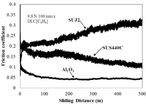
3.17 SUJ2 SUS440C DLC 9.8 N
100 mm/sec
SUJ2
0.4 0.2
0.3 ~ 0.4
SUS440C 0.2
0.05 3.18
SUJ2 SUS440C
2 1
DLC
Fig. 3.17 Friction coefficient-sliding distance data of SUJ2 (carbon steel), SUS440C (stainless steel) and alumina balls against DLC films
Fig. 3.18 Optical images of the wear scars of SUJ2 (carbon steel), SUS440C (stainless steel) and alumina balls against DLC films
3. 5
1) Holm Archard (
Ein h: )
2)
3) (Ein N: L
)
1) :Eh 2) :Ew 3)
:Ee 4) :Ep 5) :Ec
3 (1)
(2) R. Holm; Electric Contact (1946), pp.214
(3) J.F. Archard, The temperature of rubbing surfaces, Wear, Vol.2, (1959), pp.438-455 (4) K.Hokkirigawa, K.Kato, An experimental and theoretical investigation of ploughing,
cutting and wedge formation during abrasive wear, Tribology International, Vol. 21, (1988), pp.51-57
(5) S.Miyake, Tribological properties of hard carbon films: extremely low friction mechanism of amorphous hydrogenated carbon films and amorphous hydrogenated SiC films in vacuum,, Surface Coating and Technology, Vol.54-55, (1992), pp.563-569 (6) F.P. Bowden and D. Tabor, The Friction and Lubrication of Solids, (1954), Oxford (7) M. M. Khruschov, A new method for the determination of wear of machine parts, Wear,
Vol.3, (1960), pp.60-71
(8) M. M. Khruschov, Wear measurement with the aid of scintillation suppression,,Wear Vol.23, (1973), pp.225-229
(9) M. M. Khruschov, A method of testing the wearing ability of finished steel surfaces, Wear Vol.26, (1973), pp.45-51
(10) M. M. Khruschov, Principles of abrasive wear, Wear, Vol.28, (1974), pp.69-88
(11) E.Robinowicz, The Determination of the Compatibility of Metals through Static Friction Tests, ASLE Transactions, Vol.14, (1971), pp.198-205
(12)
(13) V. L. Popov; Contact Mechanics and Friction, (2010), pp. 271-284, Springer (14) E.Robinowicz; Friction and wear of materials, John Wiley &Sons, inc., (1995) (15) T. O. Mulhearn, L. E. Samuels, The abrasion of metals: A model of the process, Wear,
Vol.5, (1962), pp.478-498
(16) Dorner-Reisel, L.Kubler, G.Irmer, G.Reisel, V.Klemm, E. Muller, Characterisation of nitrogen modified diamond-like carbon films deposited by radio-frequency plasma enhanced chemical vapour deposition, Diamond & Related Materials, Vol.14, (2005), pp.1073-1077
(17) A. Beheshti, M. M. Khonsari, A Thermodynamic Approach for Prediction of Wear Coefficient Under Unlubricated Sliding Condition, Tribology Letters, Vol.38, (2010), pp.347-354
(18) S. Jahanmir: International Conference on Fundamentals of Tribology Cambridge, Mass., (1980), pp.455
(19) P.Kallas, Indentation energy and abrasive wear of metals, Wear, Vol.198, (1996),
(20) J.F. Archard, The temperature of rubbing surface, Wear, Vol.2, (1959), pp.438-455 (21) D. Majcherczak, P. Dufrenoy and Y. Berthier Tribological, thermal and mechanical
coupling aspects of the dry sliding contact, Tribology International, Vol.40, (2007), pp.834-843
(22) H. Mohrbacher, B. Blanpin, J. P. Celis and J. R.Roos (1995), Frictional Behaviour of Diamond-like carbon and diamond coatings in oscillating sliding, Surface and Coatings Technology, Vol.62, (1993), pp.583-588
(23) H. Mohrbacher, J.P. Celis, and J. R. Roos, Laboratory testing of displacement and load induced fretting, Tribology International, Vol.28, (1995), pp.269-278
(24) H. Mohrbacher, and J. P. Celis, Friction mechanisms in hydrogenated amorphous carbon coatings, Diamond and Related Materials, Vol.4, (1995), pp.1267-1270 (25) S. Fouvry, P. Kapsa, L. Vincent, Fretting behaviour of hard coatings under high
normal load, Surface and Coatings Technology, Vol.68-69, (1994), pp.494-499
(26) S. Fouvry, P. Kapsa, L. Vincent, Analysis of sliding behaviour for fretting loadings:
determination of transition criteria, Wear, Vol.185, (1995), pp.35-46.
(27) S. Fouvry, P. Kapsa, L. Vincent, Wear analysis in fretting of hard coatings through a dissipated energy concept, Wear, Vol.200, (1996), pp.186-205
(28) S. Fouvry, P. Kapsa, H. Zahouani, L. Vincent, Wear analysis in fretting of hard coatings through a dissipated energy concept, Wear, Vol.203-204, (1997), pp.393-403.
(29) S. Fouvry, T. Liskiewicz, P. Kapsa, S. Hannel, E. Sauger, An energy description of wear mechanisms and its applications to oscillating sliding contacts, Wear, Vol. 255, (2003), pp.287-298
(30) T. Liskiewicz, S. Fouvry, B. Wendler, Impact of variable loading conditions on fretting wear, Surface and Coatings technology, Vol.163-164, (2003), pp.465-471.
(31) T. Liskiewicz, T., and S. Fouvry, Development of a friction energy capacity approach to predict the surface coating endurance under complex oscillating sliding conditions, Tribology International, Vol.38, (2005), pp.69-79i
(32) Aghdam, A. B. and Khonsari, M. M., Prediction of wear in reciprocating dry sliding via dissipated energy and temperature rise, Tribology Letters, Vol.50, (2013), pp 365- 378.
DLC
4.
3
) )
) 4) 5)
5
Quinn(1)
700 Wang (2) 52100
200
1930 Blok(3)(4), Jaeger(5)
Archard (6)
2
(7)
%
DLC 400
4. 2
Holm-Archard
(8) DLC DLC
N5.4DLC N7.3DLC N10.7DLC
DLC
4. 2. 1 4. 2. 1. 1
3 4 DLC DLC
SUJ2 SUS440C DLC
9.8 N 100 mm/sec 1000 m
4. 2. 1. 2 DLC DLC
(100)
DLC DLC (011)
(0 1) MVK-G2500AT
100, 200, 300, 500 gf 3 4
3 × 4 12
DLC
(9)
DLC
I Irwin
(total work of fracture)
2
GT=2 GT= 2 + Wp
Wp
Fig. 4.1 Schematic side view of a radical in crack of a coating film and substrate configuration.
4.1
2C 4.1
1/2 C
A
/ /
(4.2)
4.1 C A
/
/ /
d=0 1/2 C = C0
[(C0/C)3-1] 1/C a =2d/ (Gf/Gs+
Ef/Es) SEM
4. 2. 1. 3
DLC (FE-
SEM)1 10 (Winroof) 1
4. 2. 2
4. 2. 2. 1 DLC DLC
a) DLC DLC
4.2 (a)~(d) Si Si DLC N5.4DLC N7.3DLC N10.7DLC SEM SEM
(4.8) [(C0/C)3-1] 1/C
4.3 C0 Si (4.8)
a
4.3 Gs= 2
= 3.04 J/m2 Es=180 GPa Ef DLC
Gf Gf = 2 4.1
N7.3DLC SEM
N7.3DLC
Table 4.1 Surface energy of DLC and nitrogenated DLC films
Film Young s modulus
(GPa)
gradient
(J/m2) Si (substrate) 180
DLC 263 5.66 x 10⁻⁵ 548
N5.4DLC 221 1.02 x 10⁻⁵ 821
N7.3DLC 193 4.69 x 10⁻⁵ 2470
N10.7DLC 173 5.66 x 10⁻⁵ 749
Si DLC N5.3DLC N7.4DLC N10.7DLC Fig. 4.2 (a) SEM images of cracks generated from edges of indentation mark on Si and
DLCs films: Load 500g
Si DLC N5.3DLC N7.4DLC N10.7DLC
Fig. 4.2 (b) SEM images of cracks generated from edges of indentation mark on Si and DLCs films: Load 300g
Si DLC N5.3DLC N7.4DLC N10.7DLC
Fig. 4.2 (c) SEM images of cracks generated from edges of indentation mark on Si and DLCs films: Load 200g
Fig. 4.3 Gradient obtained by crack length data from DLC films on Si
b) DLC DLC
4.4 (a) N5.4DLC 4.4 (b)
SEM
10 10
(a) SEM image of wear particles on N5.4DLC film
(b) Image analysis of initial wear particles
Fig. 4.4 Image analyses of wear particles on N5.4DLC film generated by tribo-test
4.5 (a)~(d) DLC, N5.4DLC N7.3DLC N10.7DLC
1
10 nm 10 nm 1 m 10 nm
DLC 10 nm
10 nm 1
/
4.2 DLC DLC
Fig. 4.5 (a) Wear particle size distribution of DLC film against alumina ball.
Fig. 4.5 (b) Wear particle size distribution of N5.4DLC film against alumina ball.
Fig. 4.5 (c) Wear particle size distribution of N7.3DLC film against alumina ball.
Fig. 4.5 (d) Wear particle size distribution of N10.7DLC film against alumina ball.
Table 4.2 Volume/surface area ratio of wear particles obtained from wear particle size
c) DLC DLC
/
(Wear particle creation energy: WPCE) 4.3 ~ 4.6 DLC, N5.4DLC, N7.3DLC, N10.7DLC
DLC
µm m
DLC DLC
ppm DLC
Table 4.3 Wear energy of DLC film obtained by a product of the estimated wear particle surface area and measured surface energy in terms of input energy generated in each tribo-test
Input energy
(J)
Wear volume Surface area Wear
Particle creation energy (J)
Wear/Input ratio
3) (m3) 2) (m2)
84 2.45I104 2.45I10-14 3.80I105 3.80I10-7 1.04I10-4 1.24×10⁻⁶ 126 7.52I104 7.52I10-14 1.17I106 1.17I10-6 3.21I10-4 2.54×10⁻⁶ 177 1.16I105 1.16I10-13 1.80I106 1.80I10-6 4.96I10-4 2.80×10⁻⁶ 235 2.24I105 2.24I10-12 3.47I106 3.47I10-5 9.56I10-4 4.07×10⁻⁶
Table 4.4 Wear energy of N5.4DLC film obtained by a product of the estimated wear particle surface area and measured surface energy in terms of input energy generated in each tribo-test
Input energy
(J)
Wear volume Surface area Wear
particle creation energy (J)
Wear/Input ratio
3) (m3) 2) (m2)
292 2.74I105 2.74I10-13 7.04I106 7.04I10-6 2.89I10-3 9.90×10⁻⁶ 530 4.00I105 4.00I10-13 1.03I107 1.03I0-5 4.22I10-3 7.96×10⁻⁶ 865 6.97I105 6.97I10-13 1.79I107 1.79I10-5 7.35I10-3 8.50×10⁻⁶ 1463 9.67I105 9.67I10-13 2.49I107 2.49I10-5 1.02I10-2 6.97×10⁻⁶
Table 4.5 Wear energy of N7.3DLC film obtained by a product of the estimated wear particle surface area and measured surface energy in terms of input energy generated in each tribo-test
Input energy
(J)
Wear volume Surface area Wear
particle creation energy (J)
Wear/Input ratio
3) (m3) 2) (m2)
137 1.76I105 1.80I10-13 3.04I106 3.04I10-6 3.76I10-3 3.74×10⁻⁵ 559 5.07I105 5.10I10-13 8.77I106 8.77I10-6 1.08I10-2 1.94×10⁻⁵ 1141 8.84I105 8.80I10-13 1.53I107 1.53I10-5 1.89I10-2 1.66×10⁻⁵ 1440 9.97I105 9.80I10-13 1.72I107 1.72I10-5 2.13I10-2 1.48×10⁻⁵
Table 4.6 Wear energy of N10.7DLC film obtained by a product of the estimated wear particle surface area and measured surface energy in terms of input energy generated in each tribo-test
Input energy
Wear volume Surface area Wear
particle
Wear/Input ratio
3) (m3) 2) (m2)
4. 2. 2. 2 SUJ2 SUS440C
SUJ2 SUS440C DLC
DLC DLC
/
20 J/m2 (10)
a) SUJ2 SUS440C
FE-SEM 1 10 Winroof
4.6 (a) FE-SEM
DLC SUJ2 4.6 (b)
4.7 (a) (b) SUS440C FE-SEM DLC
SUJ2 SUS440C
4.8 (a) (b) DLC
4.7
(a) SEM image of wear particles of SUJ2
(b) Image analysis of wear particles of SUJ2
Fig. 4.6 Image analysis of wear particles of SUJ2 generated by tribo-test
(a) SEM image of wear particles of SUS440C
(b) Image analysis of wear particles of SUS440C
Fig. 4.7 Image analysis of wear particles of SUS440C generated by tribo-test
Fig. 4.8 (a) Wear particle size distribution of SUJ2 against alumina ball.
Fig. 4.8 (b) Wear particle size distribution of SUS440C against alumina ball.
Table 4.7 Volume/surface area ratio of wear particles obtained from wear particle size distributions for SUJ2 and SUS440C
Ball material Particles volume ( m3)
Particles surface area ( m2)
Surface/volume ratio
SUJ2 0.231 13.6 59.0
b SUJ2 SUS440C
4.8 SUJ2 4.9 SUS440C
DLC DLC
µm m
SUJ2 SUS440C ppm
Table 4.8 Wear energy of SUJ2 obtained by a product of the estimated wear particle surface area and the surface energy in terms of energy input generated in each tribo-test
Input energy
(J)
Wear volume Surface area Wear
particle creation Energy (J)
Wear/Input ratio ( m3) (m3) ( m2) (m2)
8 1.81I104 1.81I10-14 1.07I106 1.07I10-6 2.14I10-5 2.67 ×10⁻⁶ 50 3.82I104 3.82I10-14 2.25I106 2.25I10-6 4.51I10-5 9.02 ×10⁻⁷ 395 5.40I104 5.40I10-14 3.19I106 3.19I10-6 6.37I10-5 1.61×10⁻⁷ 972 7.96I104 7.96I10-14 4.70I106 4.70I10-6 9.39I10-5 9.66×10⁻⁸ 1749 1.05I105 1.05I10-13 6.20I106 6.20I10-6 1.24I10-4 7.08×10⁻⁸ 2961 1.22I105 1.22I10-13 7.20I106 7.20I10-6 1.44I10-4 4.86 ×10⁻⁸
Table 4.9 Wear energy of SUS440C obtained by a product of the estimated wear particle surface area and the surface energy in terms of input energy generated in each tribo-test
Input energy
(J)
Wear volume Surface area Wear
particle creation energy (J)
Wear/Input ratio ( m3) (m3) ( m2) (m2)
4. 2. 3
4. 2. 3. 1 DLC DLC
Jahanmir(11)
Rosenfield(12)
1 mm3 100
22 mm3 10000 104 mm3 5
DLC 10 mJ
10 nm 10 nm
600 1
joule
4. 2. 3. 2
DLC N5.4DLC N10.7DLC N7.3DLC
N7.3DLC DLC
N7.3DLC
G = 2 + Wp Wp
DLC DLC
/ 4.9
(13) 4.10 DLC
DLC 10
/ ( )
/ N7.3DLC
7.3 mass% DLC
Wp G
DLC C-N Takai (14)
Shield Arc Ion Plating (SAIP) 0V 500V CNx
[N]/[C] CNx
300V (15) Lee
Takai(16) SAIP CNx CNx
CNx
/ Martron (17) IBD (Ion
Beam Deposition), DC magnetron sputtering, ECR (Electron Cyclotron Resonance) 3 DLC C-N XPS, RBS (Rutherford
Backscattering Spectrometry), AES (Auger Electron Spectroscopy)
[N]/[C] C-N C C5 C4N2 CN
C-N / 7.3 mass % DLC
Fig 4.9 Plastic and elastic regions of penetration work of nano-indentation
Fig 4.10 Plastic energy / total work energy ratio of DLC and nitrogenated DLC films
4. 2. 3. 3 SUJ2 SUS440C
4.11 SUJ2 SUS440C
SUJ2
SUS440C SUS440C SUJ2 1
4.12 SUJ2 SUS440C DLC
/ SUJ2 SUS440C
/
DLC /
Fig 4.11 Relationship between input energy and wear particle creation energy of SUJ2 and SUS440C
Fig 4.12 Wear particle creation energy/input energy ratios of DLC film,
4. 2. 4
1) DLC
DLC DLC N5.3DLC N7.4DLC
N10.7DLC 548, 821, 2466, 749 J/m2
N7.4DLC
2) Winroof DLC DLC
ppm
3) DLC SUJ2 , SUS440C
ppm /
DLC
SUJ2 SUS440C
4. 3
1881 Hertz
(18) 1971 Johnson, Kendall, Roberts
Hertz (JKR ) (19) JKR
Hertz
( ) (20)
JKR Hertz
4. 3. 1
1881 H.R. Hertz(18)
4. 3. 1. 1
4.13 O
a
a O r p
k
4.13 a 2 a3/3
(2/3) a3k P
Fig. 4.14 Displacement of semi-infinite plate
J.V.Boussinesq(20) P
4.14 C P s
z
z
s D
C
P=ps ds d
4.15 D P = pds sd
(4.13) C r O a
p C
Fig. 4.15 Displacement of contact surface
4.15 mn
O mn h h
mn 2 oh rsin mh
mh h s O r
r (4.10) p(r )
a
r s
ds
n m
o r' h
D
C
0
Fig. 4.16 Deformation in the adjacent of the contact point
4.16 O E1, E2,
1, 2
1 2 = 1+ 2 O r
S1, S2 S1 1= z1+ 1 , S2 2= z2+
2
(4.19)
z1
r R2
O(x4) 0 (4.23) (4.22)
(4.20), (4.21), (4.24), (4.25) (4.26)
r r2 0
a (4.29)
(4.28), (4.30)
p0 (4.10)
4. 3. 1. 2
R1= R0 R2
øìòíí÷
p0
4. 3. 1. 3
4.17
Fig. 4.17 Stress evaluation region in the adjacent contact point
O
O P z Hertz
J.V.Boussinesq(20) 4.18
O
r O' O
øìòíì÷
øìòíë÷
O a p (4.34)
(4.35) (4.34) z
O (4.34) r (4.36)
a
z z x)r = 0, y)r = 0 z)r = 0
z z 45
p
1 1
øìòíé÷
= 0.3 z=0.637a 1)max= 0.33p
1)z= 0 = (1-2 )p/4 0.1p
p (4.10) (4.38)
= 0.3 z = 0.47a 1)max= 0.31p
0.31p 0.47a
4. 3. 1. 4
E1 210 GPa DLC E2 263 GPa 1= 2
= 0.3 9.8 N 4.19 (4.33)
9.8 N 50 m
4. 3. 2 4. 3. 2. 1
(4.33)
9.8 N, 19.6 N, 29.4 N = /2r
(4.43) 4.10
Table 4.10 Elastic energy dependent on load in the steel ball Load
(N)
Displacement ( m) Strain Elastic energy (mJ)
9.8 0.9 1.9I10-4 0.2
19.6 0.14 3I10-4 0.5
29.4 0.18 4I10-4 0.9
1 mJ
4. 3. 2. 2 4.20
4.21 t t F
S =F/S
= / t
=G
U 1/2 F
U
S S= (r2-(r-t)2)= (2rt-t2)