Studies on System Design for Indoor Infrared Wireless Communication
屋內赤外線通信用システム設計に関する研究
March 2014
Graduate School of Global Information and Telecommunication Studies Waseda University
Optical Wireless Technologies Research Ⅱ
Dimitar Radkov KOLEV
ACKNOWLEDGEMENTS
I am highly indebted to many individuals who have helped me to accomplish this work.
First, I would like to extend my sincere thanks to Prof. Mitsuji Matsumoto, for the constant support and kind advice throughout my study at GITS, Waseda University. His guidance have been invaluable and made the whole research and daily life in Japan enjoyable.
I would also like to express my gratitude to my doctoral thesis review panel which included Prof. Takuro Sato, Prof. Shigeru Shimamoto and Prof. Toshitaka Tsuda from GITS, Waseda University. I am grateful for their kind acceptance to be reviewers and judges of my doctoral thesis as well as their valuable comments on my thesis.
I am deeply indebted to all the FSO group members especially Dr. Kazuhiko Wakamori and Takahiro Kubo for always being ready to share their extensive knowledge and provide expert opinion.
I am very grateful to my past and present colleagues in Matsumoto Lab. I appreciate the kind inputs and suggestions I received from Mr. Kamugisha Kazaura, Mr.
Mohammad Shah Alam, Mr. Bekkali Abdelmoula, Mr. Chen Jiehui, Mr. Pham Tien Dat, Mr. Liu Peng and Ms. Ben Naila. Your guidance and support are highly appreciated.
Many thanks to all the GITS faculty members and staff who helped me to conduct my research and assisted me not only in campus life but also in everyday matters.
I would also like to thank the Ministry of Education, Culture, Sports, Science and Technology of Japan for the scholarship which enabled me to come and pursue graduate studies in Japan.
And finally, my deepest thanks to my wife Mary and my family for their constant support that gave me the strength to pursue my studies to the end so far from home.
TABLE OF CONTENTS
ACKNOWLEDGEMENTS i
LIST OF TABLES iv
LIST OF FIGURES v
LIST OF ACRONYMS vii
LYST OF SYMBOLS AND NOTATION x
SUMMARY xiv
1. INTRODUCTION 1
1.1 Indoor optical wireless communications (OWC) 3
1.2 Main research contribution 6
1.3 Organization of the thesis 8
2. INDOOR OPTICAL WIRELESS COMMUNICATION SYSTEMS 11
2.1 Introduction 11
2.2 IR OWC systems 13
2.3 Ambient light noise 14
2.4 Optical receiver 18
2.5 Eye Safety 21
2.6 Beam propagation model for indoor space 26
2.7 Indoor OWC configurations 31
2.8 Conclusion 32
3. NON-DIRECTED LOS INDOOR OWC FOR GIGABIT EPON ACCESS AND
ISDB-T TELEVISION BROADCASTING 33
3.1 Introduction 33
3.2 Synchronization 37
3.3 Internet access – downlink 43
3.4 OFDM-based services – downlink 46
3.5 Internet access – uplink 50
3.6 Results and discussion 52
3.7 Conclusion 58
4. CUSTOM LOS DIRECTED AND HYBRID INDOOR OWC LINKS FOR MOBILE
USERS 60 4.1 Custom LOS directed indoor OWC network for mobile users 60
4.1.1 Introduction 60
4.1.2 System design 62
4.1.3 Results and discussion 65
4.1.4 Conclusion 67
4.2 Custom LOS hybrid indoor OWC network for mobile users 67
4.2.1 Introduction 67
4.2.2 Positioning system 69
4.2.3 Downlink with tracked narrow beam 70
4.2.4 Non-directed – uplink 72
4.2.5 Results and discussion 73
4.2.6 Conclusion 75
5. Critical analysis of the results and performance enhancement 77
5.1 Critical analysis 77
5.2 Performance enhancement – multipoint-to-multipoint network 80
5.2.1 Localization system 80
5.2.2 Tracking system and multiple devices 84
5.3 Conclusion 85
6. CONCLUSION 86
6.1 Summary of the studies 86
6.2 Future work 88
REFERENCE 89
APPENDIX List of academic achievements 98
LIST OF TABLES
2.1 Comparison of RF and IR properties for indoor wireless communication 12 2.2 Medical conditions caused by lasers at different wavelengths 22 2.3 Accessible emission limits for continuous-wave lasers 26
3.1 Mathematical analysis parameters 52
3.2 ISDB-T standard parameters 54
4.1 Mathematical analysis parameters 74
5.1 Device position information table 80
LIST OF FIGURES
2-1 Indoor wireless network examples for RF and optical links 11
2-2 Indoor OWC technologies – VLC and IRC 13
2-3 Indoor IR OWC downlink: a) conventional system; b) proposed system 14 2-4 Angular distribution of the emitter radiant intensity for Lambertian source 14 2-5 Spectral power densities of three ambient light sources 15
2-6 Long pass filter transmission 16
2-7 Electrical modulation spectrum of tungsten filament lights 17 2-8 Electrical modulation spectrum of: (a) low frequency fluorescent lights; (b) high-
frequency fluorescent lights 18
2-9 Nonimaging optical concentrators: (a) hemisphere with planar optical filter, (b) hemisphere with hemispherical optical filter, (c) CPC with planar optical filter 19
2-10 Responsitivity of different photodiodes 21
2-11 Maximum received power into the eye 24
2-12 AEL dependence on NHZ for different beam waists ω0 and angles of divergence θ in the transmitter aperture: (a) For fixed ω0=20mm and different tanθ; (b) For fixed
tanθ=0.25 and different ω0 25
2-13 Gaussian beam: a) distribution; b) spot and received power approximation 27
2-14 Gaussian beam propagation in indoor space 29
2-15 Configurations of infrared links 31
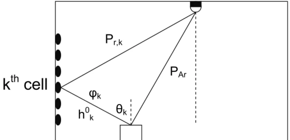
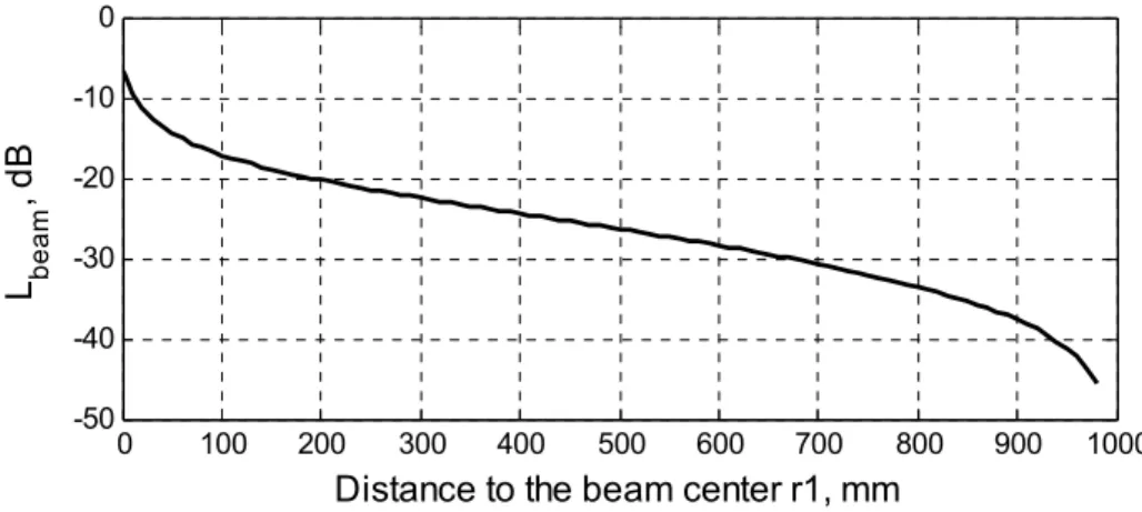
3-1 Lbeam distribution in the beam spot 35
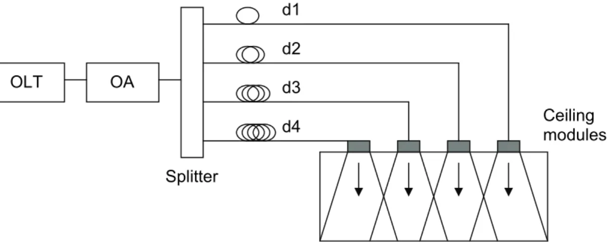
3-2 Multiple ceiling transmitters for full room coverage 35 3-3 Non-directed uplink with a grid of ceiling receivers 36 3-4 Comparison between: a) EPON structure; and b) proposed structure 38
3-5 Delay equalization in the fiber part 38
3-6 Cell arrangement: a) ceiling; b) communication plane; c) maximum distance in the ceiling grid; d) maximum distance in the communication plane 39
3-7 Different paths for different transmitters 40
3-8 Optical signals delay distribution in the overlapped area 41
3-9 Discovery process 42
3-10 Proposed scheme – Downlink 44
3-11 OFDM communication structure 46
3-12 OFDM signal spectrum 47
3-13 Proposed scheme – Uplink 51
3-14 BER vs GOA for 1Gbps downlink for different receiver apertures and beam spot
diameters 53
3-15 ISDB-T television standard 54
3-16 CNDR vs GOA and OMI/subcarrier for D=2m and dr=20mm 55 3-17 CNDR vs GOA and OMI/subcarrier for D=3m and dr=20mm 56 3-18 CNDR vs GOA and OMI/subcarrier for D=2m and dr=15mm 56 3-19 BEP for QPSK, 16-QAM and 64-QAM related to GOA 57
3-20 BER vs transmitted optical power for 1Gbps Uplink 58 4-1 Ceiling module with wide beam configuration: a. single transmitter; b. array of
transmitters 60
4-2 Directed LOS indoor optical wireless link 61
4-3 a) 2D MEMS mirror; b) CCD image sensor 62
4-4 System design: a. Ceiling module; b. Mobile device module 64 4-5 Relation between BER and Transmitted optical power for 1Gbit/s indoor laser
link 66
4-6 Proposed system for hybrid indoor LOS network 69
4-7 Positioning system 69
4-8 Downlink scheme 71
4-9 Uplink scheme 73
4-10 BER vs Transmitted optical power for a 1Gbps Uplink 74
4-11 BER vs Optical gain in a 10Gbps downlink 75
5-1 a) data transfer windows in a cycle; b) position of mobile devices; 81 5-2 Positioning system with a single imaging sensor 82 5-3 LOS issues for design with single transmitter and grid of sensor modules 83 5-4 Communication and switching time windows for system with single and double
transmitters 84
5-5 Better coverage with multiple LOS transmitters 85
LIST OF ACRONYMS
AEL Acceptable Emission Level
AOA Angle of Arrival
APD Avalanche Photo Diode
ASE Amplified Spontaneous Emission
AWGN Additive White Gaussian Noise BEP Bit Error Probability
BER Bit-Error Rate
CATV Cable TV
CCD Charge Coupled Device
CM Ceiling Module
CMOS Complementary metal–oxide–semiconductor CNDR Carrier to Noise plus Distortion Ratio
CPC Compound Parabolic Concentrator CTM Ceiling Transmit Module
DTM Discovery Time Window
EDFA Erbium-Doped Fiber Amplifier EMS Electrical Modulation Spectrum
E/O Electro-Optical
EPON Ethernet over Passive Optical Network
FOV Field of View
FSO Free-Space Optics
FTTH Fiber to the Home
GPON Gigabit-capable Passive Optical Network HDTV High Density Television
IFFT Inverse Fast Fourier Transformation
IMD Intermodulation Distortion
IMD3 Third Order Intermodulation Distortion IM/DD Intensity Modulated Direct Detection IR Infrared
IrDA Infrared Data Association
ISDB-T Integrated Services Digital Broadcasting International
LAN Local Area Network
LD Laser Diode
LED Light Emitting Diode
LLID Logical Link ID
LLN Law of Large Numbers LOS Line-of-Sight
LTE Long-term Evolution
MAC Media Access Control
MD Mobile Device
MEMS Micro Electro Mechanical Systems MPE Maximum Permissible Exposure
NHZ Nominal Hazard Zone
OA Optical Amplifier
OFDM Orthogonal Frequency-Division Multiplexing OLT Optical Line Terminal
OMI Optical Modulation Index
ONU Optical Network Unit
OOK On-Off Keying
OWC Optical Wireless Communications
PAN Personal Area Network
PD Photo Diode
P2MP Point-to-Multi-Point PIN-PD p-i-n Photo Diode PLC Power Line Communication PON Passive Optical Network PSD Power Spectral Density
OLED Organic Light Emitting Diodes QPSK Quadrature Phase-Shift Keying QAM Quadrature Amplitude Modulation
RF Radio Frequency
RIN Relative Intensity Noise
RoF Radio over Fiber
RoFSO Radio over Free Space Optics
RxM Receiver Module
SEP Symbol Error Probability
SNR Signal-to-Noise Ratio
TDFA Thulium Doped Fiber Amplifier
TDM Time Division Multiplexing
TIA Transimpedance Amplifier
TV Television
VLC Visible Light Communications
WDM Wavelength-Division Multiplexing
WiMAX Worldwide Interoperability for Microwave Access
LIST OF SYMBOLS AND NOTATION
a Distance between two neighbor ceiling modules a3 Third order nonlinearity coefficient
an In-phase modulation symbol Ar Receiver aperture surface
B Bit rate
bn Quadrature modulation symbol BN Receiver bandwidth
c Speed of light in vacuum C Expected desired signal power
Cj Junction capacitance
cL Light speed
CNDRn Received carrier to noise plus distortion ratio per subcarrier d Delay between signals from neighbor receivers/transmitters D2(N, n) Number of intermodulation distortion products
D3(N, n) Number of intermodulation distortion products dr Receiver aperture diameter
Dw Working distance Eb Bit energy
E(θ) Emitter radiant intensity fBW Photo diode bandwidth
fc Carrier frequency
fL Focal length
FOV Field of view of the detector
G0 Optical gain
GOA Optical amplifier gain
h Height between the communication plane and the ceiling hl0 The impulse response of the direct light
hkm (t) mth impulse response of the kth source hν Photon energy
I(r) Irradiance distribution of Gaussian beam i(t) Received photocurrent
<i2ase> Mean square beat noise current
IASE ASE current
IBN Current in the PD due to the background light Id Average dark current
<i2N> The mean square optical noise current IPD Current in the pin PD
Iph DC value of the received photocurrent Is Current in the PD
<i2shot> Total shot noise
<i2th> Thermal noise mean square value
k Optical wave number
K Number of micro surface from Lambertian reflector KB Boltzmann’s constant
L1 Distance between the transmitter 1 and the receiver L2 Distance between the transmitter 2 and the receiver
Lbeam Loss due to partially received beam in the receiver aperture Lcoupling Coupling loss
Lm Loss margin Lp Path loss
Lsplit Splitter insertion loss
Ltot Total loss
Δl Optical path difference MAPD APD internal gain
mn Optical modulation index for each subcarrier mt Amplifier factor
mTotal Total OMI
N Number of subcarriers
n→ Normal vector to the surface N0 Noise energy
N1 Populations of lower laser level N2 Populations of and upper laser level na Angular spread of the beam
nk Angular spread of the k-th element
nopt(t) Noise containing the AWGN with a double-sided power spectral density nOW Additive white Gaussian noise
NR Number of reflecting elements
nsp Completeness of the population inversion for the amplifier PAr Received power in the aperture
PASE ASE noise optical power Pb Bit error probability
Pb,n Bit error probability per subcarrier PD Total transmitted power in the plane Peye Maximum optical power to enter the eye PN Noise power
P(r) Power, contained within a radius r in Gaussian beam Pout Total emitted power
PR,G,indirect Average received power from reflected light PR,G,Tot Total received power from the laser source
Pr,OW(t) total optical power, directly received from the transmitter aperture Pr,k Received power in the kth small area
Ps Symbol error probability Ps,n SEP per subcarrier PT Transmit power
q electron charge
r Distance from the z-axis
R Distance from the light emitter to the detector
r1 Distance from center of the beam to the receiving aperture Rin Feedback resistance
RLOAD Load resistance Rr Radius of the eye aperture
rz Spot waist SF Smallest feature
SNRd Signal to noise ration in the downlink SOFDM(t) OFDM signal
SR Sensor resolution Ss Sensor size
ΔS Ring surface of the beam spot T Absolute temperature
tr Rise time response Ts OFDM signal duration
Xn Complex data symbol in the nth subcarrier
z Distance on the z-axis between the transmitter and the current plane η quantum efficiency
θ Angle of divergence
θLambertian Angle from the normal to the emitting surface
λ Optical wavelength
Δνf Bandwidth of the optical band pass filter ρi Reflectivity of the surface
ρk Reflectivity of the surface of the kth source ρAPD APD responsitivity
ρRX PIN-PD responsitivity
σ2IMD Third order intermodulation distortion power φ Angle of irradiance
ω Distance out from the center axis z of the beam where the irradiance drops to 1/e2 of its value on axis
ω0 Beam radius at the waist
ωn Set of N orthogonal frequencies
Summary
In the fast-changing and dynamic world today information and telecommunication technologies play a key role in our daily lives that increases every day. Broadband access services have wider coverage and higher quality. Companies often introduce new mobile devices such as notebooks, tablets and smart phones and different applications for them.
While all this advanced technology eases us in daily life it challenges the transmission networks and their capacity to transmit big data. Fiber networks have been widely spread in the backbone networks because of their high capacity and low attenuation. Networks have been constantly evolving from fiber to the node (FTTN), providing broadband access to a neighborhood, to fiber to the home (FTTH) and even fiber to the desktop (FTTD) providing optical connection to the home or office and even to a workstation.
Fiber data rates are constantly increasing by using dense wavelength division multiplexing (DWDM), multi-core fibers and other technologies. However, the wireless network faces a big struggle for bandwidth. The new devices and applications for them allow watching high-definition (HD) video, video-conversations, multiplayer games, etc.
and require very high data rates. The insufficient bandwidth is especially noticeable in indoor spaces with high user density. The current radio-frequency (RF) technologies, such as WiMAX, LTE, Wi-Fi, etc., are very useful and comfortable at home or small office. However, in bigger offices, libraries, trains, and conference halls and so on, these systems cannot meet the user bandwidth requirements and form a bottleneck between the high speed fiber optic backbone network and the end user devices.
Optical wireless communications (OWC) are considered a very attractive alternative to the RF wireless technologies. They offer very wide bandwidth. Their coverage is limited to the areas where line of sight (LOS) or reflections can reach, which offers much better security. Most of the RF systems suffer electromagnetic interference and, for example, there are often conflicts between neighbor Wi-Fi networks. OWC electromagnetic interference immunity allows its usage together with RF systems and in RF restricted areas, such as planes, hospitals, etc. Recently, the device power consumption has also become a very important issue to consider. Telecommunication companies are one of the major energy consumers. OWC require less energy compared to the RF systems.
The main focus of this thesis is the indoor infrared (IR) OWC. There are no significant atmospheric effects on the link. Often, the indoor communication is point-to-multipoint compared to FSO links where the links are point-to-point. A conventional indoor IR OWC link assumes the usage of light emitting diode or a laser diode with wavelength around 800nm to 1000 nm as a light source. There are several significant problems that prevent these systems from becoming the dominant indoor network access technology.
First, in a system that converts the optical signal from the fiber to electrical one and then modulates the light source this electro – optical conversion is a bottleneck for the overall system performance. Second, for these wavelengths the ambient noise is quite strong and the responsitivity of the photodiode is relatively small (<0.6A/W for Si photodiode).
Finally, for the laser sources the laser safety regulations limit the transmitted optical power level. In this thesis a novel system that uses the fiber end as a light source is proposed. Such system removes the electro-optical conversion and allows direct usage of fiber bit rates in the wireless link. Furthermore, the ambient noise is much smaller and the photodiode responsitivity is much higher (0.9A/W for InGaAs photodiode) which strongly improves the performance. Last but not least, the permitted transmit power due to eye safety for the fiber wavelengths is much higher than the one for the wavelengths of conventional system. So far, when indoor optical wireless network is discussed, only Lambertian optical source has been considered. In the proposed system though the source is Gaussian beam and a new propagation model is presented. In the theoretical analysis are considered the main noise components – ASE noise from the optical amplifiers, shot noise, including the ambient noise in it, and thermal noise, which has the strongest effect in the system. For better evaluation of the OFDM signal transmission RIN noise is also considered.
The indoor OWC have are divided in two main types – LOS and diffusive. The diffusive links rely on reflections from different surfaces and provide excellent coverage.
However, because of the reflections high transmitted power is required and the multipath distortion limits the bit rate. Therefore, the main accent of this thesis is on the LOS type of link – non-directed, directed and hybrid. Up to now, directed and hybrid networks are considered to work only in point-to-point networks due to the alignment complexity. In this work very fast tracking systems with high-resolution positioning systems are
presented that allow point-to-multipoint communication for these configurations. For simplicity in the link design and transmission analysis only a network with single user has been considered.
The first work presented in this thesis is a non-directed LOS optical wireless link based on EPON. The first issue such system will have is the high attenuation in the wireless part due to the fact that only a small portion of the transmitted optical power will reach the receiver aperture and the Gaussian beam distribution. To guarantee flawless link performance in any spot of the covered area a careful investigation of the received power in each spot of the Gaussian beam is conducted and overlapping is considered. Due to overlapping arises the second main issue in the system – interference. In this work the interference in terms of time delay distribution and signal strength have been considered and possible data rates for particular configurations have been discussed. The link budget and eye safety considerations are also taken into account. In the downlink analysis two different signals were considered because of the capabilities of EPON to transmit signals on different wavelengths. Apart from the on-off-keying (OOK) modulation that is typical for internet access and other network communications, a transmission analysis for ISDB- T television broadcasting, which is based on orthogonal frequency-division multiplexing (OFDM), has been presented and its performance for some practically possible link configurations has been discussed. As a conclusion non-directed system, based on the proposed direct fiber coupling technology is not suitable for indoor communication systems because of its difficult deployment (multiple transceivers), limited speed (up to 1Gbps) and big receiver aperture that cannot be integrated in most of the portable devices.
Furthermore, the proposed system cannot transport 64-QAM signal with the required BEP.
In the second work in this thesis is a study on directed and hybrid indoor LOS links. In this type of links it is important to have a positioning (localization) and tracking system to establish and maintain the link for mobile devices. The tracking system based on MEMS mirrors and imaging sensor that is typically used in FSO communications to mitigate angle of arrival effect has been adopted. In the proposed directed system the imaging sensors are used to detect the directed transmitter on the other side of the wireless link and the MEMS mirrors are used for transmission axis alignment. The
presented link is considered to be a part of EPON network and the link alignment relies on the optical signal, sent for the protocol messages during the new device discovery time window. Maintaining of the link is relatively simple since corrections are done simultaneously with every beam change in the communication signal that is detected in the imaging sensor. The mathematical results show that the system is capable to provide gigabit speeds at very low power consumption. The receiver apertures can be in the order of a millimeter, which allows their integration in all portable devices. The main drawback remains the complexity due to the localization and tracking systems, especially in the mobile side.
The main accent in the presented hybrid configuration is to shift all the complexity to the ceiling module allowing it to operate at high data rates (10Gbps) and lower power consumption because of the directed downlink. A novel localization system based on imaging sensor and corner reflector with passive mobile device side has been presented and its capabilities- discussed. One of the main conclusions in this work is the possibility to combine the localization system together with the uplink receiver in a single module and deploy these modules on the ceiling forming grid. The simple non-directed uplink provides 1Gbps link with relatively low power consumption, especially when compared to RF solutions. Furthermore, the uplink design requires no optical amplifier and allows flexible choice of the wavelengths in the wireless part.
At the end of the thesis a critical analysis of the work and proposals for system enhancement for multiple users and multiple transmitters have been presented.
CHAPTER 1
INTRODUCTION
In the last decades the telecommunication technology has become a big and important part of our daily life. New portable devices with higher and higher technical specifications, such as smart phones and tablets, providing ease of use and full functionality at any place and any time have been constantly introduced to the market.
The rapidly increasing number of users and the growing market of applications lead to an
“explosion” of contents and create a constant demand for wider bandwidth. The deployment of fiber networks for different purposes from inter-continental connections to custom local networks and technologies like fiber to the home has significantly eased the bandwidth problems for the carriers and internet providers. Optical communications have many advantages compared to the electrical ones, namely small attenuation, high security and wide bandwidth. However, there are some areas, in which fiber networks are not applicable due to high price or convenience and radio frequency (RF) wireless technologies are implemented so far (e.g. big river crossing, building to building communication, last mile problem, etc.). Unfortunately, such RF technology cannot provide enough bandwidth, compared to the fiber one, and its usage forms a bottle neck in the network. Therefore, in the last decades many researches have been concentrating their studies on optical wireless communications (OWC) for both outdoor and indoor applications to remove the RF bandwidth limitations and allow big data transmission [1].
Of special interest are the new generation systems, based on direct fiber coupling that allow the deployment of all-optical networks with no electro-optical or optic-electrical conversion, which also normally forms a bottle neck for the network [2].
There are big challenges for the outdoor OWC due to the specifics of the transmission media. First, the attenuation in the atmospheric path can change in very wide intervals according to the weather. In sunny weather with high visibility the attenuation is extremely low but when rain, snow or fog are present the attenuation increases drastically and can lead to link disconnect. Also, when the transmitted optical beam propagates
through the atmosphere, it is affected by the refractive-index random variations, caused by inhomogeneities in the air [3].This could lead to signal fluctuations that can result in a burst error or even temporal unavailability of the free-space optical (FSO) link, which defines the low bit-error rate (BER) in on-off keying (OOK) modulation based systems as another big challenge. The most popular methods for atmospheric effects mitigation are signal modulation or combination of modulation and improved transmission and reception technologies [4-6]. To increase the received power and to soften some of the atmospheric effects, tracking systems are also widely used [7]. Outdoor FSO links are mainly used for point-to-point communication which limits their use to carrier’s networks and they cannot be used for user access networking. There are some commercially available FSO systems, but they cannot guarantee the reliability required to become a part of the backbone links and completely substitute the fiber when necessary.
From practical point of view, it is important to consider the end user behavior regarding the time and place he or she needs broadband access. From the telecommunication provider networks we can observe that there are a limited number of users in the rural areas and basically with a single base station a several kilometer area can be covered. Respectively, the bandwidth requirements of such small number of users can be covered with current RF technologies. However, in the city areas especially in the busy areas the base stations are separated from each other on hundred meters and still cannot provide enough bandwidth. Furthermore, it is unlikely for the user to use a broadband access outdoors when moving. The places with high probability for users to require fast internet connection remain indoor spaces. Nowadays, RF technologies are still able to provide network access for personal area networks (PAN), but for public places, such as offices, libraries, conference halls, trains, etc. the insufficient bandwidth has already become a serious issue. Indoor OWC are considered a very good potential alternative to RF technologies to provide broadband wireless connection in indoor spaces.
The main purpose of this research is to explore the OWC systems current issues and provide a solution that can push the OWC from potential to actual alternative that can provide sufficient broadband network access to multiple users in indoor spaces.
1.1 Indoor optical wireless communications (OWC)
Constantly new mobile technologies as Worldwide Interoperability for Microwave Access (WiMAX) [8] and Long Term Evolution (LTE) - Advanced (formally submitted as a candidate 4G system to ITU-T and finalized by 3GPP in March 2011) [9] are developed but their speed is unable to support a large number of users, concentrated in one place. New modulation and encoding schemes are developed for RF to meet the user demands but the limited bandwidth will sooner or later lead to exhaustion in new RF technologies. Furthermore, in the license-free spectrum more often RF conflicts occur (widely used Wi-Fi networks [10]). Considering the above issues indoor optical OWC have become a very attractive alternative. They operate in the gigahertz spectrum and offer significantly wide bandwidths at frequencies that are not subject to license. Optical waves cannot propagate through walls which can be considered as drawback opposed to RF waves. However, that also increases the network security since the network cannot be used outside the closed indoor space and if a third party attempts to intercept the signal that will basically lead to link disconnect. Another important feature of the OWC is their low power consumption. Telecommunication equipment is one of the biggest power consumers in worldwide scale. Furthermore, with the vast popularity of mobile devices in the last decade and introduction of new portable devices such as Smartphone and tablet with very high computing capability and wider and wider coverage of telecommunication service companies the mobile users that require broadband connection drastically increases. Networks alone are big power consumers but in close future the millions or even billions of new smart devices will increase the power needs further. The new telecommunication technologies should not only provide high speeds, sufficient for the consumer needs but also must provide very high energy efficiency. Last but not least, OWC networks operate in a different part of the RF spectrum that makes them immune to electromagnetic interference. Important difference between OWC and RF is the spatial diversity that allows several different optical links to operate on the same place without actually interfering with each other.
There are two distinguishable brands of optical communications – visible light communications (VLC), [11], and infrared (IR) laser communications [12]. VLC, also referred to as Li-Fi, relies on exchanging current light sources with light emitting diodes
(LED) and modulates their intensity in order to build a communication line. The main advantage of VLC is the double function of the current lighting system that will be used not solely for lighting but also for network access, broadcasting, localization, etc.
However, there are several serious issues that limit such systems performance. First, this type of network relies on power line communication to connect the light with actual backbone network. Power line communication can become a bottle neck between the fast backbone network and possible future gigabit VLC links. Another important issue is the light source itself – LED. The LED used for lighting is white. There are two main technologies to produce white light- by mixing the light from three different small LED – red, green and blue and blue LED with phosphor cover [13]. If such diodes are to be used for communication the synchronization of these three components will be the biggest issue since smaller changes will result in different light and that would have effect on people. The other technology is a blue LED with phosphor cover, which also results in white light. However, the phosphor leads to very long rising times which severely limit the bandwidth that can be used. Lately, organic light emitting diodes (OLED) have become a hot topic among the VLC researchers [14-16]. Currently, their practical efficiency is much lower than the LED and the theoretically anticipated one and they are not applicable for lighting systems. Furthermore, OLED can have very big size and form that means their junction capacitance is very high, which also limits the bandwidth of the system. Another important issue with the VLC technology is that it provides connectivity only when the light is on, which means such network is not applicable in all possible cases. Also, users do not like to have a strong light in their eyes when they look at the portable device, which assumes to use a different technology for the uplink and use VLC only for downlink. Important issue in these networks is that they operate in the visible light spectrum, which means that most of the ambient noise in this spectrum is hard to be filtered. Also, the transmitted power limits are much lower compared to the IR communications because of the effects that excessive power levels on this wavelengths can have on human eye.
Communications, based on infrared laser diodes are more expensive and complex since they do not use the current lighting system. However, they can offer much higher data rates and full time system operation regardless of the room lighting. It is possible to
connect the fiber directly to the wireless link that removes the electro-optical and optic- electrical conversion which is considered a bottleneck in the network. Furthermore, the ambient noise, which is critical for this type of communications, is much weaker in the infrared spectrum compared with the visible one and the communication signal can be easily separated from the noise by using optical filters. Also, the power limitations due to eye safety are much higher for wavelengths in the range of 1550nm. Higher power allows higher data-rate transmission and bigger coverage compared to the VLC links.
Of particular importance for IR OWC to become a widely used technology in commercial applications [17-21] is to allow wireless connection to a backbone cabled local area network (LAN) using the IEEE 802.11 standards without the need of changing the LAN protocols. Some commercial products that operate on Ethernet and Token ring networks were available two decades ago [22]. There has been also a research on using IR signal to transfer signals with IEEE 488 and RS-232/RS-423/RS-422 format [23-24].
IR is widely used for low cost consumer appliances such as remote controls, transmission of high quality audio signals to small portable devices [25-26] or theater stereo speakers [27-28].
One of the most successful implementations of IR technology for data communication is the Infrared Data Association (IrDA). This technology that provides interoperable, low cost, low-power, half-duplex, serial data connection has been used for two decades and even today it is available in most of the mobile devices. Its data rates increase with the network development and nowadays gigabit communication is possible. The main drawback of this technology remains to be the short operating distance and the need of directing of the devices that prevents it to be preferred in front of Wi-Fi networks.
Recently, many researches work towards an IR network that can become a part of the Ethernet network and provide the high data rates, available in the fiber networks with the mobility that RF links allow.
The research in this thesis goes one step further by considering seamless connection between the fiber network and the indoor open space and direct implementation in Ethernet over passive optical network (EPON) networks. Such solution, as shown later, could eliminate most of the problems in the conventional OWC systems because of the usage of laser diode at fiber-communication wavelengths. However, the optical source in
this case is not a diode with typical Lambertian distribution but the fiber end that has Gaussian distribution. That requires a new indoor propagation model and transmission analysis for all configurations so that precise performance evaluation can be achieved.
Since the main accent is on the transmission analysis and link performance, for simplicity a single user network is considered. In future research, based on the collected data, the configuration with best performance can be chosen and multi-user network considered.
1.2 Main research contribution
The main goal of this research is to build analytical model for indoor propagation of an IR Gaussian beam. By using the presented model here several custom designs with line- of-sight (LOS) configurations have been proposed and their performance evaluated.
So far, in indoor OWC links only Lambertian distribution has been considered [29-30], since no direct fiber coupling technology is used. For first time in the indoor OWC the Gaussian beam propagation was considered. The first primary research contribution presented in this thesis is a complete transmission analysis for a Gaussian beam for both LOS and non-LOS configurations and an approximation for the relationship between the whole optical power in a wide beam spot in the communication plane and the received power in a very small receiver aperture in it has been presented. This analysis has been used as base in the calculations for OWC system capabilities. There are many papers, showing experimental results of similar systems with seamless connection between the fiber and the air [31]. However, these works are based only on experimental setup and they lack mathematical model. Comparison between the presented analytical model and such experimental setups shows their design flaws, for example huge receiver aperture, and defines such setups as not practical solutions for future indoor OWC (the receiver aperture is not mentioned, but the analysis showed that its size in the considered experiment is huge, which was confirmed later in discussion with the paper authors). In other experimental setups the results cannot be considered correct because ambient noise power was considered in a horizontal direction, because of the link setup. However, in horizontal direction the ambient noise values are much lower because the main shot noise is from reflections, compared to a practical solution when the receiver aperture is pointed vertically and the light from sunlight or lighting system is direct.
The second important contribution is the indoor Gaussian beam propagation model for an RF signal, which is sent directly in the indoor open space from radio-over-fiber (RoF) based fiber, similar to radio-over-FSO (RoFSO) networks. However, in the RoFSO networks the communication is often point-to-point and main issue are the atmospheric effects. In the indoor network the communication is often point-to-multipoint and main problems are the ambient light noise and the multipath distortion due to reflections from different surfaces. Mathematical model for the indoor transmission of orthogonal frequency division multiplexing (OFDM) based services has been described and example with integrated services digital broadcasting international (ISDB-T) television (TV) transmission considered [32].
Based on the theoretical model, discussed above, the performance of several custom LOS configurations has been evaluated. The first work, combining OOK signal and OFDM signal in a non-directed indoor OWC is presented because of its simplicity, compared to the directed ones. The system is based on EPON standard where simple wavelength division multiplexing (WDM) can be used, combining both gigabit internet access and ISDB-T TV broadcasting. The design presented in this thesis is the latest improvement with implemented transimpedance amplifier (TIA) and more thorough noise analysis including amplified spontaneous emission (ASE) noise and relative intensity noise (RIN) that has serious effect on the OFDM signal. Other important issues, such as multiple ceiling receivers for the uplink and synchronization of the neighbor transceivers due to overlapping have been examined.
So far, for point-to-multipoint indoor access network only non-directed configuration has been considered due to its wide field of view (FOV) and broadcasting principle. The next contribution is consideration of directed and hybrid configurations for multiuser network access. An indoor OWC system with directed configuration for mobile devices high speed access, based on direct fiber coupling technology, has been presented. In directed configuration the establishing and maintaining of the link is considered to be a very sophisticated matter because of the need of tracking system. In this work novel complete scheme of scanning and tracking systems have been presented. The tracking system is based on micro electro mechanical systems (MEMS) mirror that can be used not only to track a mobile device, but also to switch between multiple users is time-
division multiplexing (TDM) is implemented. The link is compatible with EPON standard which simplifies its integration in the currently available networks without the need of new standards and protocols. The scanning system uses the EPON discovery time window and its sequence to establish the link. Tracking system has very high response because it uses the communication signal (1Gbps) to correct any position changes. Using the propagation model above mathematical analysis of the BER shows the low power consumption in the system. The complex tracking system in the mobile device side has provoked further interest for better uplink solution. That leads to the third design, presented in this thesis of a hybrid network with high speed directed downlink (10Gbps) and an uplink with diverged beam and a grid of multiple ceiling transceivers has been proposed. Furthermore, a novel localization technique that does not require transmit power from the mobile side was introduced and its performance has been evaluated.
Again, full mathematical analysis of the system performance has been conducted.
1.3 Organization of the thesis
This thesis has been organized in 5 chapters detailing the theory of indoor OWC with analytical models and several link designs with their full transmission analysis.
In Chapter 2 a conventional indoor OWC system and the new generation system with direct fiber coupling technology are explained and compared. The main focus is on the ambient noise sources, which optical and electrical modulation spectrum are shown and the main methods for their mitigation are discussed. Since the proposed links use laser diode (LD) as an optical source of particular importance are the transmit power limitations due to the eye safety regulations. The maximum permitted emission (MPE), accessible emission limit (AEL) and nominal hazard zone (NHZ) have been discussed for a diverged beam and figures with example configurations are shown. A novel mathematical model for indoor Gaussian beam propagation is introduced for both diffusion and LOS systems. For diffusion systems the model is quite similar to the one for Lambertian distribution but the Gaussian source strongly affects the end signal.
Regarding the LOS systems, the most important issue is to define the received power in a small receiving aperture in the communication plane, where the diverged Gaussian beam forms a wide beam spot. Simple approximation method is introduced and is used in all
the models, when the ratio between total optical beam power and received power is considered. Both diffusive and LOS systems advantages and disadvantages are discussed and the decision to evaluate only LOS performance is explained. Furthermore, the three LOS configurations – directed, non-directed and hybrid are introduced with simple comparison of their performance to settle preliminary performance expectations for the analysis results.
In Chapter 3 thorough transmission analysis for non-directed LOS configuration is presented considering the link budget and the main noise components, such as ASE noise, ambient light noise and thermal noise in the receiver. For the case of indoor optical transmission of RF signals, particularly OFDM-based services, such as ISDB-T TV transmission, where even small signal fluctuations can strongly affect the system performance, the RIN noise of the transmitter is also considered.
In Chapter 4 a directed LOS network, based on EPON standard with localization and tracking of the mobile device (tablet, notebook, etc.) is discussed. The tracking and localization is based on MEMS mirror and imaging sensors in both ceiling module and mobile device. Simple system performance is also presented. Furthermore, in Chapter 4 a hybrid network with 10Gbps directed downlink and 1Gbps uplink is presented. Novel localization system with very simple and passive mobile side is proposed and discussed in detail. Furthermore, the performance of a novel non-directed uplink with a grid of multiple ceiling receivers is described. The non-directed system requires higher transmit power than the directed one. In the simulation analysis is shown that event these higher power levels normally do not exceed the eye safety allowed AEL and is much lower than RF networks with similar capabilities. It is important to note that so far directed and hybrid configurations have been considered for point-to-point communication only excluding the possibility for multiple user connection. In this research I present tracking systems that not only support mobile users but also by implementing TDM they allow point-to-multipoint and multipoint-to-multipoint communications.
In Chapter 5 I provide a critical analysis of the work, presented in this thesis. The main issues of the presented configurations are discussed and possible solutions for improved system performance have been presented. Also, so far the main work was concentrated on the link transmission analysis and actual network with multiple users has not been
considered. In this chapter the cases with multiple users and transmitters for directed and hybrid configurations have been discussed.
Finally, Chapter 6 provides the concluding remarks of this thesis work. All the results are discussed and future research work is outlined.
CHAPTER 2
INDOOR OPTICAL WIRELESS COMMUNICATION SYSTEMS
2.1 Introduction
With the wide spreading of the fiber-to-the-home (FTTH) technology practically the high-speed network access is available to every indoor space. Due to the high cost and time consumption of reconfiguring and maintaining of wired systems for clustered computers in offices, education institutions, libraries and so on, wireless technologies are often preferred. Furthermore, with the growing market of portable devices such as smart phones and tablets and different applications for them the need of high speed network access increases rapidly. The widely used RF technologies today cannot provide the necessary speed between the end user and the high speed fiber network and turn into bottle neck especially in places with high user density (Fig. 2-1). Because of the license restrictions in the RF spectrum, all the networks use the license-free spectrums around 2.4GHz and 5.7GHz. This is the reason for often conflicts between neighboring networks due to their big coverage out of the indoor boundaries and raises security issues. Last but not least, telecommunication equipment is one of the main power consumers in worlds scale and power efficient networks are top priority for future development.
Figure 2-1: Indoor wireless network examples for RF and optical links [33]
Router
FTTH
Considering the above issues, indoor optical wireless systems are good alternative that can provide high speed and high security with much lower power consumption. The comparison between RF and IR communication technologies is shown in Table 2.1.
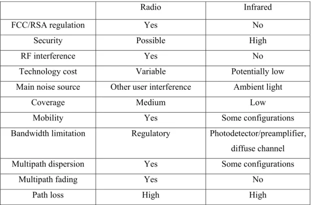
Table 2.1: Comparison of RF and IR properties for indoor wireless communication
Radio Infrared
FCC/RSA regulation Yes No
Security Possible High
RF interference Yes No
Technology cost Variable Potentially low
Main noise source Other user interference Ambient light
Coverage Medium Low
Mobility Yes Some configurations
Bandwidth limitation Regulatory Photodetector/preamplifier, diffuse channel
Multipath dispersion Yes Some configurations
Multipath fading Yes No
Path loss High High
There are two different technologies – VLC and IR laser communication (Fig. 2-2).
The VLC technology relies on future change of the incandescent and fluorescent lights with much more power efficient LED. Its main idea is to provide a dual function of the lighting system by providing connectivity. By intensity modulation of the LED communication can be established. There are several issues regarding this technology.
First, to be able to send communication signal to each LED array either power line communication (PLC) [34-35] or VLC communication between light sources is necessary.
Both will limit the maximum bit rate in the network. Another issue is the LED intensity modulation limit. Furthermore, VLC communication is affected much stronger by the ambient light noise compared to IR one, as explained later in this chapter, but the transmit power for visible light is much smaller than the permitted for IR due to eye safety limitations [36-37]. IR communications provide high speed and with feasible
connection between fiber and open space fiber network speeds can be reached in the wireless network.
Figure 2-2: Indoor OWC technologies – VLC and IRC 2.2 IR OWC systems
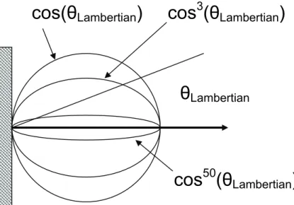
The conventional IR OWC downlink is shown on Fig. 2-3a. The optical signal from the backbone is converted to an electrical one in the local network. Such OWC uses intensity modulated direct detection (IM/DD). The optical source is an IR diode or LD with wavelength typically in the range of 800-1000nm. Such optical sources are described with the Lambertian law, according to which the angular distribution of the emitter radiant intensity E(θ) is [38, 39], Fig. 2-4:
( ) (
Lambertian)
a n
out a
P n
E θ
θ = 2π+1cos (2.1)
Where Pout represents the total emitted power and θLambertian is the angle from the normal to the emitting surface. The angular spread of the beam is defined by na.
The main problems in such system are the limited speed due to the E/O conversion and the strong ambient noise. Another issue for the laser-based systems is the eye safety limitations for the transmitted optical power. I address these problems by proposing a new generation indoor OWC link, based on seamless connection between the fiber and indoor open space (Fig. 2-3b). Such system should be able to provide the same bit rate as the fiber communications and will be independent on the signal modulation allowing wireless transmission of radio signals, coming from RoF technology. Important feature of the new signal is that the laser source is actually the fiber end and the beam is not Lambertian but rather Gaussian. In this Chapter first, a performance comparison between the proposed system and the conventional one is presented and then a complete indoor propagation model for Gaussian beam is derived.
Fiber IRC
PLC
VLC
Figure 2-3: Indoor IR OWC downlink: a) conventional system; b) proposed system;
Figure 2-4: Angular distribution of the emitter radiant intensity for Lambertian source
2.3 Ambient light noise
In both systems the signal is transmitted in to the open space and is received in the receiver aperture together with the ambient noise. Most common ambient noise sources in an indoor environment are tungsten lights, fluorescent lights, IR devices and daylight
cos(θ
Lambertian) cos
3(θ
Lambertian)
cos
50(θ
Lambertian) θ
LambertianO/E Optical
fiber
Electrical signal
Device Optical
source
Optical receiver module
Ceiling
Optical fiber
Device Optical receiver module
Ceiling
(a)
(b)
[40-42]. Fig. 2-5 shows the optical spectral power densities of these light sources.
Fluorescent light has just a small amount of IR radiation, but daylight and incandescent light present a higher amount. Tungsten is the worst source. Fluorescent light has a low power density at the wavelengths used by PD. Daylight may be a problem when terminals operate near windows. It can be suppressed by using a narrowband optical filter before the photodetector that allows just the IR frequencies used by the transmitter to hit the detector [43-44]. These kinds of filters, however, have a narrow FOV that limits their usage possibilities. The effect of the three sources of light can be considerably reduced by restricting the FOV of the receiver and by using optical filters before detection of the photodiode. As can be observed in Fig. 2-5, the ambient noise levels for the wavelengths, used by the conventional system are much higher than the ones for fiber communications wavelengths, used in the proposed new generation system.
Figure 2-5: Spectral power densities of three ambient light sources [42]
The IR receivers typically have either long pass or band pass optical filters to attenuate ambient light. Long pass filters can be thought of as essentially passing light at all wavelengths beyond the cutoff wavelength. Usually, they are constructed of colored glass or plastic, so that their transmission characteristics are actually independent of the angle of incidence. A common long pass filter and its transmission are shown on Fig. 2-6, [45].
Long pass filters are used in almost all present commercial IR systems.
Figure 2-6: Long pass filter transmission [45]
Band pass filters are constructed of multiple thin dielectric layers, and rely upon the phenomenon of optical interference. These filters can achieve narrow bandwidths, leading to superior ambient light rejection (filters with bandwidths under 1 nm are available on the market). In order to maximize the signal-to-noise ratio (SNR), however, the transmitter optical spectrum must lie within the filter bandwidth, implying that when the filter bandwidth is made small, LD transmitters need to be used. Such a filter must be implemented carefully if the receiver is intended to achieve a wide FOV. Furthermore, the band pass filters are more expensive than long pass filters and are good for WDM applications but currently not preferred for OWC links.
Long pass filters are the most commonly used in commercial infrared systems, as their transmission characteristics are greatly independent of the angle of incidence. Basically, these kinds of filters restrict the passage of light before the cutoff frequency, and, when combined with silicon photodiode, perform jointly as a band pass filter. As this type of
(a)
(b)
filter greatly depends on the receiver incident angle, it must be used with an adequate concentrator to be suitable for diffuse systems. Band pass filters are constructed of superposed dielectric slabs, and can achieve narrow optical bandwidths.
Apart from the optical spectrum of the noise sources it is important to consider the electrical modulation spectrum (EMS). In [40] the EMS for most common lighting sources has been experimentally derived.
Tungsten filament lights are the most common lighting sources nowadays. Being banned from Europe and fast replaced by the cheap, power saving, long-lasting LED bulbs in future they will no longer be an issue for the OWC. However, they are still widely spread and their effect on OWC systems must be considered. Their optical spectrum is shown on Fig. 2-5. It can be noticed that they will strongly affect optical wireless communications especially in the IR spectrum. Optical filters cannot provide effective protection against them. On Fig. 2-7 is shown their EMS. It can be noticed that the spectrum consists of very low frequencies, compared to the ones used for optical communication. Thus it is easy to filter this noise by using an electrical filter.
Figure 2-7: Electrical modulation spectrum of tungsten filament lights [40]
Figure 2-8: Electrical modulation spectrum of: (a) low frequency fluorescent lights; (b) high-frequency fluorescent lights [40]
The optical noise from fluorescent lights can be significantly reduced by using optical filter. On Fig. 2-8 is shown the EMS of both low-frequency and high-frequency fluorescent lights. These frequencies are much higher but can still be filtered on electronic level.
Strongest ambient noise will come from interference with other IR appliances, since their signal cannot be filtered with optical filter and their EMS will consist of very high frequencies.
2.4 Optical receiver
A part of the transmitted optical power will reach the receiver aperture. In an optical wireless receiver, the dominant source of shot noise in the detector arises from the ambient light levels in the environment, and the use of optical filters in many applications is required.
To be able to catch as much of the signal as possible photodiodes with large areas are required. However, such photodiodes will have high capacitance that will limit the bandwidth of the receiver. One of the widely used methods to collect maximum optical power and bring it to a small size photodiode is to use optical concentrators.
Concentrators may be of the imaging or nonimaging. The telescopes used in long-range, free-space optical links represent examples of imaging concentrators. Most short-range infrared links use nonimaging concentrators.
(a) (b)
The hemispherical lens is an important nonimaging concentrator [46-48], and is widely used in commercial infrared systems nowadays (see Fig. 2-9(a) and (b)). It achieves a wide FOV and omnidirectional gain, making it suitable for use in non-directed links.
When long pass filtering is employed, a planar long pass filter can be placed between the hemisphere and the detector, as shown in Fig. 2-9(a). When band pass filtering is utilized, it is not desirable to employ a planar filter in the configuration shown in Fig. 2-9(a). As the angle from which rays are received, shifts, so does the angle at which light strikes the filter. This shifts the filter pass band. Instead, as shown in Fig. 2-9(b), the band pass filter should be deposited or bonded onto the outer surface of the hemispherical concentrator [47-48]. Regardless of the angle from which the signal is received, rays that reach the detector are incident upon the filter at small values of the angle, minimizing the shift of the filter pass band, and maximizing its transmission. Thus with a hemispherical filter, it is possible to simultaneously obtain a narrow bandwidth and wide FOV.
Figure 2-9: Nonimaging optical concentrators: (a) hemisphere with planar optical filter, (b) hemisphere with hemispherical optical filter, (c) CPC with planar optical filter
The compound parabolic concentrator (CPC) [49] is another nonimaging concentrator that is widely used in infrared links [50]. It can achieve much higher gain than the hemisphere, but at the expense of a narrower FOV, making it very good choice for
Hemisphere
Filter Photodetector
Hemisphere
Filter
Photodetector
CPC
Filter
Photodetector
(a)
(b) (c)
directed links. As shown in Fig. 2-9(c), a long pass or band pass filter can be placed on the front surface of the CPC.
There are several important characteristics of the photodiode (PD) that strongly affect the OWC performance. The quantum efficiency η is the number of the electron–hole carrier pairs generated per incident–absorbed photon of energy hν and is given by:
η ν
h P
q I
Ar
= s (2.2)
Is is the photocurrent generated by a steady-state optical power PAr incident on the photodetector, q is the electron charge and hν is the Plank constant.
In a PD, responsivity measures the electrical output per optical input and is given by [51]:
ν ρ η
h q
RX = (2.3)
The equation (2.3) is valid for p-i-n photo diode (PIN-PD). Avalanche photodiodes (APD) have an internal gain MAPD.
APD RX
APD ρ M
ρ = (2.4)
The responsitivity of the PD is different for different wavelengths and depends from the semiconductor, used to create the PD as shown on Fig. 2-10. It is important to choose a PD that can detect the transmitted optical signal from the laser diode and combine with optical filters accordingly. A closer look in Fig. 2-10 shows that the typical PD for conventional systems with wavelengths 800nm to 1000nm is the silicon one which has responsitivity under 0.6A/W. In comparison, the fiber communication wavelengths 1310nm and 1550nm require InGaAs PD which is more expensive, but has responsitivity around 0.9A/W. Therefore, the proposed system will have much higher efficiency than the conventional ones.
Figure 2-10: Responsitivity of different photodiodes [52]
Junction capacitance (Cj) is another important characteristic of the photodiode as this can have a significant effect on the photodiode's bandwidth and response. It should be noted that larger diode areas encompass a greater junction volume with increased charge capacity. In a reverse bias application, the depletion width of the junction is increased, thus effectively reducing the junction capacitance and increasing the response speed. A load resistor will react with the photodetector junction capacitance to limit the bandwidth.
For best frequency response, a 50 Ω terminator should be used in conjunction with a 50 Ω coaxial cable. The bandwidth (fBW) and the rise time response (tr) can be approximated using the junction capacitance (Cj) and the load resistance (RLOAD) [51].
BW r
j load BW
t f
C f R
35 . 0
2 1
=
= π
(2.5)
2.5 Eye Safety
The high level of ambient noise and big angle of divergence of the beam increase the demands of higher transmit optical power in order to achieve sufficient SNR. Since some of the conventional systems and the proposed one use LD and will be used in close contact with people for long time (several hours) it is important to consider the effect on
the human body and guarantee that it is not dangerous. Of special concern in such IR networks is the fact that lasers are used for communication. The skin is much less sensitive than the eye and therefore if a system is eye safe it is safe for the human body generally. Laser effect on human eyes changes with the laser wavelength. The eye focuses visible and near-infrared light onto the retina. A laser beam can be focused to intensity on the retina which may be up to 200,000 times higher than at the point where the laser beam enters the eye. Most of the light is absorbed by melanin pigments in the pigment epithelium just behind the photoreceptors, and causes burns in the retina.
Ultraviolet light with wavelengths shorter than 400 nm tends to be absorbed by lens and 300 nm in the cornea, where it can produce injuries at relatively low powers due to photochemical damage. Infrared light mainly causes thermal damage to the retina at near- infrared wavelengths and to more frontal parts of the eye at longer wavelengths. The table below summarizes the various medical conditions caused by lasers at different wavelengths, not including injuries due to pulsed lasers.
Table 2.2: Medical conditions caused by lasers at different wavelengths
Wavelength Pathological effect
180 - 315nm photokeratitis (inflammation of the cornea, equivalent to sunburn) 315 - 400nm photochemical cataract (clouding of the eye lens) 400 - 780nm photochemical damage to the retina, retinal burn
780 - 1400nm cataract, retinal burn
1.4 - 3μm aqueous flare (protein in the aqueous humour), cataract, corneal burn
3μm - 1mm corneal burn
When a high intensity laser light from the visible spectrum enters the eye, the normal protection is blinking which will decrease the laser effect and will warn the human to avoid direct looking in the laser beam. IR lasers are very dangerous because a human cannot see them and there is no blinking. Therefore, it is necessary to obey the eye safety laser restrictions as defined by standard ANSI Z 136.1 and IEC 60825-12 [36-37].
Lasers have been classified by wavelength and maximum output power into four classes and a few subclasses. A Class 1 laser is safe under all conditions of normal use.
This means the MPE cannot be exceeded when viewing a laser with the naked eye or
![Figure 2-1: Indoor wireless network examples for RF and optical links [33]](https://thumb-ap.123doks.com/thumbv2/123deta/9851718.1898011/29.892.184.717.803.1033/figure-indoor-wireless-network-examples-rf-optical-links.webp)
![Figure 2-5: Spectral power densities of three ambient light sources [42]](https://thumb-ap.123doks.com/thumbv2/123deta/9851718.1898011/33.892.249.642.523.813/figure-spectral-power-densities-ambient-light-sources.webp)
![Figure 2-10: Responsitivity of different photodiodes [52]](https://thumb-ap.123doks.com/thumbv2/123deta/9851718.1898011/39.892.264.619.162.428/figure-responsitivity-of-different-photodiodes.webp)