IEICE TRANS. FUNDAMENTALS, VOL.E102–A, NO.5 MAY 2019
729
LETTER
VHDL Design of a SpaceFibre Routing Switch
Alessandro LEONI†a), Pietro NANNIPIERI†b),Nonmembers,andLuca FANUCCI†c),Member
SUMMARY The technology advancement of satellite instruments re- quires increasingly fast interconnection technologies, for which no stan- dardised solution exists. SpaceFibre is the forthcoming protocol promising to overcome the limitation of its predecessor SpaceWire, offering data-rate higher than 1 Gbps. However, while several implementations of the Space- Fibre IP already exist, its Network Layer is still at experimental level. This article describes the architecture of an implemented SpaceFibre Routing Switch and provides synthesis results for common FPGAs.
key words: SpaceFibre, SpaceWire, RoutingSwitch, satellite networks, FPGA
1. Introduction
Increasingly accurate payload instruments, such as modern Synthetic Aperture Radars (SAR) and optical detectors, are requiring data-rates above the Gbps, for which the widely adopted SpaceWire[1]technology cannot be used anymore.
The typical solution is to use non-standard protocols based on Texas Instruments TLK2711, which must be developed ad-hoc and do not provide advanced features such as Quality of Service (QoS) and Fault Detection Isolation and Recov- ery (FDIR). SpaceFibre[2] will solve this problem, while adding at the same time advanced features like: i) automatic error recovery logic, providing a reliable link; ii) token- based flow control to prevent buffer overflows; and iii) highly configurable QoS mechanisms by means of hardware sepa- rated Virtual Channels (VCs)[3]. Moreover it will maintain compatibility at packet level with SpaceWire. Each Virtual Channel can be configured independently according to pri- ority levels, expected bandwidths and allocated time-slots, giving total flexibility to the system engineers and allowing to use the same interconnection technology for both payload data (requiring high bandwidth and low reliability) and plat- form data (requiring high reliability and strict timing but low data-rates). SpaceFibre, as well as SpaceWire, may be used to connect several instruments to the on-board mass memory through Routing Switches. However, due to the high com- plexity of SpaceFibre, only one Routing Switch has been developed so far by StarDundee Ltd[4], which does not cur- rently include the Multicast mechanism. In this paper, the architecture of a SpaceFibre Routing Switch with Multicast
Manuscript received October 9, 2018.
Manuscript revised January 4, 2019.
†The authors are with Department of Information Engineering, University of Pisa, Italy.
a) E-mail: [email protected] b) E-mail: [email protected] c) E-mail: [email protected]
DOI: 10.1587/transfun.E102.A.729
feature is described.
2. Architecture Overview
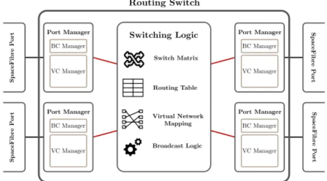
In this chapter, the architecture of the developed SpaceFibre Routing Switch is described. It relies, for the implementa- tion of the SpaceFibre ports, on the SpaceFibre Codec IP developed by IngeniArs s.r.l., which has been deeply tested and validated on-field during years. A key feature of the presented Routing Switch is that it can be instantiated with a generic number of ports, each one with a generic num- ber of VCs. This is very important considering that, most likely, instruments will need only few VCs (one or two), while the connection towards the on-board mass-memory will need more of them to support different Quality of Ser- vices. A global overview of the design is represented in Fig. 1. As can be seen, each SpaceFibre port is connected to a Port Manager before arriving to the Switching Logic. The Port Manager has the role to simplify the management of the requests generated by (and addressed to) its correspon- dent port, by handling the so-called wormhole connections.
SpaceFibre uses the wormhole mechanism as its forwarding scheme, meaning that once a VC of an output port begins to accept data from a VC of an input port, it cannot be reas- signed to any other port until the packet is finished. The Port Manager keeps track of the status of the port, both in case of transmission from the port to the Switching Logic (input port) and from the Switching Logic to the port (output port).
The Switching Logic is the core of the Routing Switch: its role is to manage the connections and forward the packets.
To do so, it comprises several elements:
• A Switching Matrix, which establishes the physical con-
Fig. 1 Overview of the Routing Switch architecture showing its main internal blocks.
Copyright © 2019 The Institute of Electronics, Information and Communication Engineers
730 IEICE TRANS. FUNDAMENTALS, VOL.E102–A, NO.5 MAY 2019
nections between input and output ports;
• A Routing Table, which is accessed to derive the output port of a packet depending on its header. The Routing Table is bypassed in case the packet uses the Path Ad- dressing scheme instead of the Logical Addressing, i.e., when the output port is directly specified into the packet itself instead of specifying a globally known identifier of the destination;
• A Virtual Network Table, used to map each tuple
<Port,VC> to a certain Virtual Network number. Ac- cording to the standard, only VCs belonging to the same Virtual Network can be connected together;
• An Inverse Virtual Network Table, mapping the tuples
<Port,VirtualNetwork> to the corresponding VC. This table is not strictly necessary, but it greatly speeds up the setup of connections, as explained later;
• A Broadcast Logic block, handling the forwarding of broadcast messages according to the standard specifi- cations.
The Switching Matrix is implemented with a non-blocking switching logic, which allows to reach full bandwidth trans- mission without any dependency on the number of simulta- neous connections (there are no contended buffers between input and output ports), at the cost of additional logic. The Virtual Network Table must be configurable by the user and is not hard-wired, thus the Switching Matrix must allow to connect every VC to every other possible VC, even if most of these connections are not used depending on the Virtual Net- works configuration. This greatly increases the complexity of the design depending on the number of ports instantiated and the number of their VCs.
3. Main Features
SpaceFibre is a flexible protocol and it supports several network-level features, such as:
• Multicast: a packet can be forwarded to multiple output ports at the same time according to its header;
• Group Adaptive Routing: the output port of a packet can be chosen from a set of possible output ports, choosing the first available one;
• VC Timeout: whenever the transfer of data from an in- put port to the connected output port requires more time than expected (higher than this timeout), the wormhole is closed, and the remaining part of the packet is dis- carded.
The Routing Switch presented here supports all these mech- anisms. Both the Multicast and the Group Adaptive Routing have been implemented through dedicated additional logic in the Switching Matrix and in the Routing Table, which provides a set of ports for each Logical Address. These two mechanisms are mutually exclusive. The multicast imple- mentation obviously increases the complexity of the system, leading to a higher utilisation and lower maximum achiev- able frequency. However, as shown in Table 1 of the next
Fig. 2 Routing Table containing information on the output ports, Multi- cast, Group Adaptive Routing and header deletion for the allowed Logical Addresses (32 to 255).
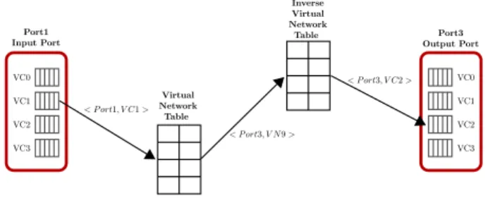
Fig. 3 Logic steps to derive the VC in the output port belonging to the requested Virtual Network.
section, the impact is acceptable. The Routing Table con- tains information on whether the header deletion must be applied for each output port in the output set or not, i.e., whether the first byte of the packet, containing the address, must be removed or not. A representation of the Routing Table is shown in Fig. 2. In addition to the Routing Ta- ble, a configurable Virtual Network Table is implemented to associate each <Port,VC> with its correspondent Virtual Network. When a new packet arrives, the requested out- put port is initially found accessing the Routing Table. The next step is to find the VC in the output port belonging to the same Virtual Network of the input VC. Figure 3 shows the steps of this decoding process involving the access to both the Virtual Network Table and to the Inverse Virtual Network Table. In this example case, the packet arrives on
<Port 1, VC 1>, which belongs to Virtual Network 9, and requests the output Port 3. It is clear that having an Inverse Virtual Network Table allows to find the associated output VC through one single memory access, at the cost of little additional RAM and logic used. Without it, it would have been necessary to access the Virtual Network Table multiple times until the associated output Virtual Channel has been found for each output port, leading to a worst case scenario of NxM accesses, being N the number of ports and M the number of Virtual Channels per port.
The VC Timeout is completely supported, with the ad- ditional feature (not described in the standard) that, in case it is used together with Multicast transmission, only the worm- hole towards the output port causing the delay is closed so that the transmission can resume for the other ports. This is particularly important when using Multicast to increase the hot redundancy of the overall system: in case one of the hot redundant links fails, only its port is removed. Another important aspect in a SpaceFibre Routing Switch is how to
LETTER
731
arbitrate multiple input ports when they request the same output port. The standard does not specify any algorithm, leaving the choice to the designer. A Round Robin (RR) scheduling is implemented in the proposed Routing Switch.
The RR approach grants the fairness among the ports and prevents deadlock situations, in which an input port always gets the right to transmit to the requested output port, pre- venting the others to transmit. A RR Arbiter circuitry, based on the design described in[5], is instantiated for each tuple
<Port, VC>, keeping track of the pending requests.
4. Synthesis Results
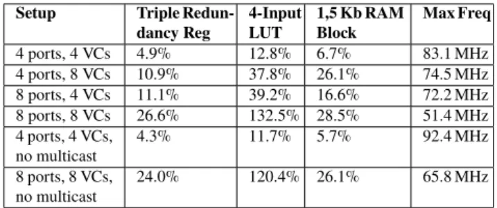
The Routing Switch has been synthesized for different tech- nologies, considering both common FPGAs used for lab- oratory equipment (e.g. Electronic Ground Support Equip- ment and link analysers) and radiation hardened FPGAs that are suitable in the near future to host a SpaceFibre Rout- ing Switch. Please note that the presented results include all the logic embedded in the Switching Block as shown in Fig. 1, while the SpaceFibre ports are not included as they are not part of this work. Common implementations of a SpaceFibre port require low hardware resources on common space and commercial FPGAs[6],[7]. The Xilinx Virtex- 6 XC6VLX240T and the Xilinx Zynq XC7Z045 have been chosen as commercial products and the Microsemi RTG4 as space-grade FPGA. Being the number of ports and the num- ber of VCs the factors that affect the most the complexity of the design, several synthesis runs have been made to study the impact of these parameters. The tools used to synthesize are Xilinx ISE 14.6 and Xilinx Vivado 2016.4, respectively for the Virtex-6 and the Zynq, and Synplify Pro 14 for the RTG4. An idea of the complexity of the Multicast mech- anism can be obtained from the two extra synthesis results shown in Table 1, where the resource utilization without Multicast is presented for two configurations.
Table 1, Table 2 and Table 3 report the synthesis results for the three FPGAs together with the maximum estimated clock frequency. As expected, increasing the number of ports and/or their VCs we obtain a more complex design: i.e. using 8 ports with 8 VCs each leads to the impossibility to fit the design in the RTG4. This is not to be considered a problem, as for the interconnection backbones ASIC solutions are usually preferred in flight hardware. The Routing Switch fits instead in the commercial solutions even with a larger number of ports and VCs, where an FPGA solution is usually adopted. Considering the internal datapath 36 bits wide, the frequency goal to reach a link rate of 2.5 Gbps is 62.5 MHz, which is achieved in most of the cases.
5. Conclusion
This paper describes the architecture of a SpaceFibre Rout- ing Switch implementing all the mandatory and optional features foreseen by the SpaceFibre standard and provides some synthesis results for different technologies and under
Table 1 Synthesis results for Microsemi RTG4.
Setup Triple Redun- dancy Reg
4-Input LUT
1,5 Kb RAM Block
Max Freq
4 ports, 4 VCs 4.9% 12.8% 6.7% 83.1 MHz
4 ports, 8 VCs 10.9% 37.8% 26.1% 74.5 MHz
8 ports, 4 VCs 11.1% 39.2% 16.6% 72.2 MHz
8 ports, 8 VCs 26.6% 132.5% 28.5% 51.4 MHz
4 ports, 4 VCs,
no multicast 4.3% 11.7% 5.7% 92.4 MHz
8 ports, 8 VCs,
no multicast 24.0% 120.4% 26.1% 65.8 MHz
Table 2 Synthesis results for Xilinx Virtex-6.
Setup Single bit Reg
6-Input LUT
18 Kb RAM Blocks
Max Freq
4 ports, 4 VCs 2.1% 9.8% 0.5% 187.1 MHz
4 ports, 8 VCs 5.3% 24.3% 0.5% 163.5 MHz
8 ports, 4 VCs 6.2% 26.1% 1.0% 164.2 MHz
8 ports, 8 VCs 14.9% 78.8% 1.0% 140.4 MHz
Table 3 Synthesis results for Xilinx Zynq.
Setup Single bit Reg
6-Input LUT
18 Kb RAM Blocks
Max Freq
4 ports, 4 VCs 1.7% 5.9% 0.18% 205.3 MHz
4 ports, 8 VCs 3.8% 16.4% 0.18% 188.8 MHz
8 ports, 4 VCs 3.9% 15.9% 0.36% 192.1 MHz
8 ports, 8 VCs 9.4% 50.3% 0.36% 161.4 MHz
different configurations. The results demonstrate that the presented Routing Switch can be implemented on commer- cial FPGAs with a large number of ports and VCs, but also on space-grade FPGAs, limiting the number of ports and VCs.
References
[1] European Cooperation for Space Standardization ECSS, “ECSS-E- ST-50-12C, SpaceWire — Links, nodes, routers and networks,” http://
ecss.nl/standard/ecss-e-st-50-12c-spacewire-links-nodes-routers-and- networks, accessed Oct. 8. 2018.
[2] European Cooperation for Space Standardization ECSS, “ECSS- E-ST-50-11C-DIR1, Space engineering — SpaceFibre — Very high- speed serial link,” http://ecss.nl/standard/ecss-e-st-50-11c-dir1, ac- cessed Oct. 8. 2018.
[3] S. Parkes, C. McClements, D. McLaren,a, A.F. Florit, and A.G. Vil- lafranca, “SpaceFibre: A multi-Gigabit/s interconnect for spacecraft onboard data handling,” IEEE Aerospace Conference Proceedings, March 2015.
[4] S. Parkes, C. McClements, D. McLaren, A. Ferrer Florit, and A. Gon- zalez Villafrance, “SUNRISE: A SpaceFibre Router,” DASIA Confer- ence, Tallinn, Estonia, May 2016.
[5] P. Gupta and N. McKeown, “Designing and implementing a fast cross- bar scheduler,” IEEE Micro, vol.19, no.1, pp.20–29, Feb. 1999.
[6] M. Rowlings and M. Suess, “An experimental evaluation of SpaceFibre resource requirements,” International SpaceWire Conference, Sept.
2014.
[7] P. Nannipieri, G. Dinelli, D. Davalle, and L. Fanucci, “A SpaceFibre multi lane codec system on a chip: Enabling technology for low cost satellite EGSE,” PRIME 2018 - 14th Conference on Ph.D. Research in Microelectronics and Electronics 8430317, pp.173–176, July 2018.