博士後期学位論文
Corrosion resistance and tribological properties
on surface of DLC films-coated metal substrate
prepared by IBED
IBED 法を用いた DLC/金属の成膜表面における
耐食耐摩耗特性に関する研究
韓 貝貝
i
ABSTRACT
Diamond-like carbon (DLC) films exhibit high hardness, low friction, excellent wear resistance, high anticorrosion resistance, good biocompatibility, high surface tension with water, and optical transparency in various fields such as the automotive, aerospace, communication and biomedical industries. In this study, diamond-like carbon (DLC) films were deposited successfully on magnesium alloy AZ31 substrate as hard protective film by ion-beam-enhanced deposition with various CH4/H2 ratio, gas flow rates and
accelerating voltages. The composition and mechanical properties of the DLC coatings were characterized using scanning electron microscopy (SEM), Raman spectroscopy, Rockwell test, and micro-indentation. The tribological properties of the coating were also investigated using a frictional surface microscope with an in situ observation system and friction force measurements. The DLC films were characterized by a lower intensity ratio of the D-peak to G-peak (ID/IG), higher hardness, and improved tribological properties when deposited at a lower accelerating voltage (6 kV). At the CH4/H2 ratio of 1:99 and 6
sccm/6 kV, minimum ID/IG values of 0.62, relatively low friction force value of 0.12 N, and a maximum hardness of 4056 HV were attained respectively. In addition, the DLC film exhibited improved wear resistance and a shallower wear track at this condition.
The characterizations and corrosion behaviors of the DLC-coated stainless steel and titanium which used in bipolar plates deposited with different gas ratios CH4/H2 and
ii
SEM and AFM. The element compositions of cross-section were determined by Electron probe microanalysis (EPMA). The DLC-coated stainless steel and titanium were corroded by potentiostatic polarizations in a 0.5mol/L sulfuric acid solution at 90 ℃ for 168 h and the corrosion behaviors were investigated in the solution using electrochemical techniques. In addition, the metal ions in sulfuric acid corrosion solution were detected by inductively coupled plasma (ICP) atomic emission spectroscopy. The results indicate that a higher CH4/H2 ratio for titanium and a lower CH4/H2 ratio for stainless steel can
result in a decreasing ID/IG ratio, low root mean square (RMS) of the surface morphology and low concentration of metal ions in corrosion solution. The ID/IG ratio of corroded DLC coating on titanium with a minimum of 0.827 is lower than that of corroded DLC coating on stainless steel with a minimum of 1.03. The significant improvement in the corrosion resistance of DLC film was mainly attributed to the increased sp3 bond element and formation of passive film. The minimum resistivity of 12.9 mΩ·cm2 for DLC
film-coated SUS316L is obtained, which is higher than that of 7 mΩ·cm2 for DLC film-coated titanium. The metal ions concentration of a DLC coating on titanium with a minimum of 0.34 ppm is obviously lower than that of a DLC coating on stainless steel with a minimum of 16.60 ppm. The corrosion mechanism of stainless steel is proposed. As a result, , the localized corrosion of a point or small area has been significantly improved after depositing the DLC films, the DLC films-coated titanium substrate is more promising in the applications with the superior anti-corrosion properties.
I
Contents
Chapter 1 Introduction ... 1
1.1 Research background and significance ... 1
1.2 Performance characteristics and mechanical application of magnesium alloy substrate ... 3
1.2.1 Mechanical application of magnesium alloy ... 3
1.2.2 Tribological properties of magnesium alloy ... 5
1.3 Application of titanium and stainless steel materials for fuel cells and surface modification methods ... 9
1.3.1 Application of titanium and stainless steel for fuel cells ... 9
1.3.2 Surface modification methods for titanium and stainless steel ... 11
1.4 Performance characteristics of Diamond-Like Carbon films ... 14
1.4.1 DLC films ... 14
1.4.2 Problems of DLC films-coated metal substrate ... 18
1.5 Thesis objective and structure ... 19
References ... 22
Chapter 2 Experimental methods and principle ... 29
2.1 Preparation of DLC films ... 29
2.1.1 Experimental materials and substrate processing ... 29
2.1.2 Deposition of DLC films on different substrates ... 30
2.2 Experimental analysis methods ... 33
2.2.1 Raman analysis ... 33
2.2.2 Micromorphology analysis ... 34
2.2.3 XPS analysis ... 37
2.2.4 TEM analysis... 40
2.3 Analysis of hardness and tribological behavior ... 41
2.4 Corrosion performance analysis ... 43
2.4.1 Corrosion test ... 43
2.4.2 Corrosion behavior DLC films ... 45
References ... 48
Chapter 3 Surface characteristics and tribological properties of DLC films on magnesium alloy ... 51
3.1 Chemical bonding structure of DLC films ... 51
II
3.3 Cross-section morphology and thickness analysis of DLC films ... 56
3.4 Tribological properties of DLC films ... 59
3.5 Summary ... 65
References ... 67
Chapter 4 Microstructure analysis and corrosion resistance of DLC films-coated titanium ... 69
4.1 Surface and cross-section morphology of DLC films deposited on titanium... 69
4.1.1 Surface morphology and roughness ... 69
4.1.2 Cross-sectional morphology and thickness ... 72
4.2 Chemical composition and microstructure analysis of DLC films deposited on titanium ... 76
4.2.1 Raman spectroscopy of DLC films on titanium ... 76
4.2.2 TEM analysis of DLC films on titanium ... 78
4.2.3 XPS analysis of DLC films on titanium ... 80
4.3 Interfacial Contact Resistance of DLC films deposited on titanium ... 82
4.4 Corrosion resistance of DLC films-coated titanium ... 83
4.4.1 Surface characteristics of DLC films-coated titanium after corrosion ... 83
4.4.2 Effect of DLC films on metal ions dissolution ... 85
4.4.3 Electrochemical behaviors of DLC films deposited on titanium ... 86
4.5 Summary ... 88
References ... 91
Chapter 5 Chemical composition and corrosion behavior of DLC films-coated stainless steel ... 95
5.1 Surface and cross-section morphology of DLC films deposited on SUS316L .... 95
5.1.1 Surface morphology and roughness ... 95
5.1.2 Cross-sectional morphology and thickness ... 99
5.2 Chemical composition and microstructure analysis of DLC films deposited on SUS316L ... 103
5.2.1 Raman spectroscopy of DLC films on SUS316L... 103
5.2.2 TEM analysis of DLC films on SUS316L ... 106
5.2.3 XPS analysis of DLC films on SUS316L ... 107
5.3 Interfacial Contact Resistance of DLC films deposited on SUS316L ... 109
5.4 Corrosion behavior of DLC films-coated SUS316L ... 110
5.4.1 Surface characteristics of DLC films-coated SUS316L after corrosion... 110
5.4.2 Effect of DLC films on metal ions dissolution ... 114
III
5.5 Summary ... 117
References ... 119
Chapter 6 Conclusion ... 123
6.1 Discussion and summary ... 123
6.2 Future work ... 125
Related Publications ... 127
1
Chapter 1 Introduction
1.1 Research background and significance
The movement of mechanical parts is always accompanied by friction and wear [1, 2]. A large number of industrial parts fail because the surface properties are inability to meet the severe friction and wear service conditions such as heavy load and high speed conditions [3]. Magnesium alloys have recently been widely applied as structural materials because of their light weight, high dimensional stability, excellent electromagnetic shielding and damping performance, excellent machinability, and easy of recycling [4, 5]. They are practically used in various fields such as the automotive, aerospace, communication and biomedical industries. However, the poor hardness, abrasion resistance, and corrosion resistance of magnesium alloys limit their application [6]. Modification of the material surface is an effective means to improve these properties to enable the use of magnesium for more machine parts [7].
2
such as distributing the air to a gas diffusion layer-electrodes assembly uniformly, removing heat and water flow from the active areas, providing the electrical contact and carrying current from adjacent cells [12]. So it is necessary to reduce the cost and the large mass of these components for the commercial application of PEFC fuel cells [13]. For the development of PEMFCs, bipolar plates should have the characteristics such as high anticorrosion resistance, high electrical conductivity, lightweight, high mechanical manufacturability, high surface tension with water and low cost [14].
3
plate is necessary by various surface modification techniques. Therefore, in this paper DLC films were deposited on the surface of magnesium alloy substrate by IBED to improve the tribological properties, and on the surface of titanium and stainless steel substrate to protect the bare metallic bipolar plate from the highly acidic environment. The hardness and wear resistance on surface of DLC films-coated AZ31 magnesium alloy were analyzed. The optimal conditions were found to improve wear resistance and a shallower wear track. The characterizations and corrosion behaviors of the DLC films-coated titanium and stainless steel were investigated and evaluated. The chemical bonding structure and composition of the DLC coatings were analyzed to obtain the mechanism of anti-corrosion.
1.2 Performance characteristics and mechanical application of
magnesium alloy substrate
1.2.1 Mechanical application of magnesium alloy
4
The advantages of magnesium and magnesium alloys are listed as follows,
lowest density of all metallic constructional materials;
high specific strength; good castability, suitable for high pressure die-casting;
can be turned/milled at high speed;
good weldability under controlled atmosphere;
much improved corrosion resistance using high purity magnesium;
readily available;
compared with polymeric materials: better mechanical properties; resistant to ageing;
better electrical and thermal conductivity; recyclable.
One of the reasons for the limited use of magnesium has been some poor properties exacerbated by a lack of development work. The disadvantages of magnesium are presented based on the following:
low elastic modulus;
limited cold workability and toughness;
limited high strength and creep resistance at elevated temperatures;
high degree of shrinkage on solidification;
high chemical reactivity;
in some applications limited corrosion resistance.
5
instrument panels, seats, gear boxes, air intake systems, stretcher, gearbox housings, tank covers etc. Magnesium based alloys have been used for numerous applications in hobby equipment e.g. bicycle frames. In communication engineering, light weight is required as well as screening against electro–magnetic radiation which plastic materials cannot offer. Magnesium alloy, the lightest metallic construction material with high strength/weight ratio, high thermal conductivity, good machinability and recyclability, is considered as the most promising green engineering material in the 21st century [19, 20]. Therefore, magnesium and its alloys are attracting great interest as they have enormous promising potential applications in the automotive, aircraft, aerospace, electronic industries, biological materials and so on [21]. For some lightweight soft matrix materials such as aluminum alloys, although they have the characteristics of light weight and high specific strength, their surface wear resistance is poor, which seriously affects the safety and reliability of these parts.
1.2.2 Tribological properties of magnesium alloy
6
worn parts must be replaced and this entails both a problem of an economic nature, due to the cost of replacement, and a functional problem, since if these components are not replaced in time, more serious damage could occur to the machine in its complex. This phenomenon, however, has not only negative sides, indeed, it is often used to reduce the roughness of some materials, eliminating the asperities. Erroneously we tend to imagine wear in a direct correlation with friction, in reality these two phenomena cannot be easily connected. There may be conditions such that low friction can result in significant wear and vice versa. In order for this phenomenon to occur, certain implementation times "are required, which may change depending on some variables, such as load, speed, lubrication and environmental conditions, and there are different wear mechanisms, which may occur simultaneously or even combined with each other:
1. Adhesive Wear; 2. Abrasive Wear; 3. Fatigue Wear; 4. Corrosive Wear;
5. Rubbing Wear or Fretting; 6. Erosion Wear;
7. Other minor wear phenomena (Wear by Impact, Cavitation, Fusion, Wear-Spreading).
7
time it is possible to reduce adhesion by increasing surface roughness and hardness of the surfaces involved, or by inserting layers of contaminants such as oxygen, oxides, water or oils. In conclusion, the behavior of the adhesive wear volume can be described by means of three main laws.
The abrasive wear consists of the cutting effort of hard surfaces that act on softer surfaces and can be caused either by the roughness that as tips cut off the material against which they rub (two-body abrasive wear), or from particles of hard material that interpose between two surfaces in relative motion (three-body abrasive wear) [25, 26]. At application levels, the two-body wear is easily eliminated by means of an adequate surface finish, while the three-body wear can bring serious problems and must therefore be removed as much as possible by means of suitable filters, even before of a weighted machine design.
8
The rubbing wear occurs in systems subject to more or less intense vibrations, which cause relative movements between the surfaces in contact with the order of the nanometer [28]. These microscopic relative movements cause both adhesive wear, caused by the displacement itself, and abrasive wear, caused by the particles produced in the adhesive phase, which remain trapped between the surfaces. This type of wear can be accelerated by the presence of corrosive substances and the increase in temperature [29].
The erosion wear occurs when free particles, which can be either solid or liquid, hit a surface, causing abrasion [30]. The mechanisms involved are of various kinds and depend on certain parameters, such as the impact angle, the particle size, the impact velocity and the material of which the particles are made up.
Among the factors we find hardness, mutual solubility and crystalline structure affecting wear [31]. It has been verified that the harder a material is, the more it decreases. In the same way, the less two materials are mutually soluble, the more the wear tends to decrease. Finally, as regards the crystalline structure, it is possible to state that some structures are more suitable to resist the wear of others, such as a hexagonal structure with a compact distribution, which can only deform by slipping along the base planes.
9
1.3 Application of titanium and stainless steel materials for fuel
cells and surface modification methods
1.3.1 Application of titanium and stainless steel for fuel cells
With the civilization of mankind, present world energy scenario reveals that within the next few decades conventional fuel resources will face severe shortage and taking into concern environmental pollution by using fossil fuel, fuel cell will be one of the most promising power sources [32] for future. Fuel cell generates electricity and heat by converting the chemical energy stored in a fuel. Depending upon the fuel used and operating conditions, fuel cells are subdivided into various types. Among all the fuel cells, proton exchange membrane (PEM) fuel cell is the most promising power sources for residential and mobile applications [33]. A recent technical cost analysis indicates that the cost of the platinum electrode accounts for about 50% of the PEM fuel cell cost, whereas the bipolar plates rank second in cost depending upon the material used and process development and leads up to 80% of the total weight [34].
The biggest challenge for the development of PEM fuel cell for automotive application is the reduction of cost and weight of the bipolar plate. Thus, widespread applications of PEM fuel cell rely heavily on both cost and weight reduction of bipolar plate. The main purposes [35] of the bipolar plates in PEM fuel cells are:
1) distribution of reactant gases uniformly over the active areas 2) collection of electrons,
3) connection of two adjacent cells, 4) heat removal from adjacent cells,
10
To achieve this goal the bipolar plate should have the following properties: 1) should have less porosity with high mechanical strength,
2) high electronic conductivity and low contact resistance, 3) high thermal conductivity,
4) integrated uniform cooling channel, 5) high corrosion resistance.
11
a higher mechanical strength than the stainless steel but the higher cost. The corrosion behavior of the metallic bipolar plate can degrade the fuel cell performance because the proton conductivity of the polymeric electrolyte membrane is decreased due to the poison of Fe, Cr and Ni ions.
1.3.2 Surface modification methods for titanium and stainless steel
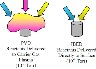
Tribological coatings such as titanium nitride are usually deposited by glow- discharge, physical vapor deposition (PVD) processes such as activated reactive evaporation, cathodic arc sputtering, or magnetron sputtering [38]. In these processes coating reactants are transported to, and combined together in a glow-discharge carrier gas plasma. The reactions that occur when the reactants are combined in the glow-discharge carrier gas are driven primarily by the energetics of the glow-discharge. Therefore the metallurgical, morphological, and mechanical properties of the coatings deposited are determined by the thermodynamic environment in the discharge. Once submerged in the glow-discharge the reactants cannot be controlled individually, and optimizing one coating feature such as grain size may have to be done at the expense of another feature such as density or adhesion.
12
major differences between the IBED and PVD processes are summarized in Table 1. Compared with the other coating techniques, the Ion beam enhanced deposition (IBED) method has many advantages such as lower compressive stress due to the production of a graded interfacial, higher film-substrate adhesion, better surface properties of high-precision parts and be selective surface modification, which enables a series of beneficial surface property modifications without detrimentally affecting the bulk properties.
Fig. 1- 1 Reactant delivery differences: PVD versus IBED.
13
automotive, truck, aircraft, aerospace, medical, and general machinery.
Table 1- 1 IBED and PVD process comparison
PVD IBED
Reactant delivery
Into plasma atmosphere surrounding parts Simultaneous, directly to surface of parts
Reaction chemistry
Thermally driven by plasma temperature Kinetically driven by kinetic energy of ions
Reaction atmosphere (pressure) 10-3 Torr with high partial pressures of (H2, H2O, O2, CO2)
10-6 Torr with low partial pressures of (H2, H2O, O2, CO2)
Reaction vessel temperature
> 400 °C < 93 °C
Coating morphology
Crystalline, grains 1-50 micron dimensions Semi-amorphous, grains sub-micron dimensions Coating adhesion
Thermal diffusion driven, interlayer needed Ballistic-alloyed, no interlayer needed
14
double glow discharge plasma technique by Jiang Xu et al. [40]. The film has the better electrochemical behavior, electrical conductivity, corrosion resistance and surface wettability than the uncoated titanium alloy. In addition, the preparation method of C film was introduced in the patent by Jiang Xu et al in order to achieve the thicker film and the lower electrical conductivity. Compared with the CVD techniques [41] the Ion beam enhanced deposition (IBED) method provided coatings with lower compressive stress. Depositing DLC films is one of the methods to control corrosion. To overcome these drawbacks, depositing a protective coating on the metallic bipolar plate is necessary by various surface modification techniques.
1.4 Performance characteristics of Diamond-Like Carbon films
1.4.1 DLC films
15
16
layers of the film material to mix into the surface. Then, an alloyed bond layer is formed to pro-mote adhesion of the film. Film–substrate adhesion is achieved without the external application of heat, and processing temperatures can be held below 93°C (200°F); therefore, no physical dimensions are produced [38]. Accordingly, the primary advantage of IBED is selective surface modification, which enables a series of beneficial surface property modifications without detrimentally affecting the bulk properties [53].
17
In the last 10 years DLC film have gained special attention due to their properties such as low friction coefficient, high chemical stability, high hardness, optical transparency, high electrical resistivity and low electron affinity [54, 55]. Thereby they can be used in optoelectronic devices, protective films for tribological or chemical applications, automotive parts and tools, coatings for dies or molds and biological parts. In this paper, the friction property and corrosion property were analyzed.
An important factor affecting the hardness of the film is the content of the hybrid bond sp3 [56]. In general, the higher the content of the hybrid bond sp3, the closer the hardness of the film is to diamond [57]. Since the structure and composition of the film obtained by different preparation methods are different, the hardness of the film can be adjusted within a wide range, and the highest hardness can reach 90 GPa. However, the problem of internal stress is also considered. The high hardness of the film is always accompanied by a high internal stress, and the excessive internal stress causes the wear resistance of the film to be seriously reduced, thereby seriously affecting the mechanical properties of the film. At present, researchers use doping N, Si, Cr and other elements in the film to perform low-temperature short-time heat treatment or to prepare a gradient film to reduce the internal stress of the film.
18
consumable parts such as bearings and gears [61, 62]. The film has good chemical stability, prevents acid and alkali and organic solution erosion, and is suitable for chemical mechanical parts and coatings of various decorative parts without changing the size of mechanical parts.
Harbin Institute of Technology used plasma immersion ion implantation and deposition technology to deposit the film on the aerospace space flywheel bearings [63-65]. The results show that the film's stable friction coefficient is only 1/3 of the substrate, and the surface friction and wear performance is greatly improved, which is beneficial to extend the life expectancy of the space flywheel bearing. In order to solve the problem of high wear of cutting tools in the wet environment of wood processing, the oxygen-free and anaerobic films were deposited on low-alloy working steel using the PVD method by Wolfgand et al [66]. It was found that the oxygen-free film in the humid environment showed excellent wear resistance. The IBM Company has developed a micro-drilled film-coated micro-drill for drilling fine holes in the circuit board [67, 68]. It has been found that the drilling speed of the micro-drill increases the service life by a factor of two, and the processing cost of the drill is reduced. Some scholars have succeeded in depositing films on wearable mechanical components such as automobile engine parts, plates, nails, etc. [69, 70], and the friction coefficient is 0.14.
1.4.2 Problems of DLC films-coated metal substrate
19
For the development of PEMFCs [74-77], bipolar plates should have the characteristics such as high anticorrosion resistance, high electrical conductivity, lightweight, high mechanical manufacturability, high surface tension with water and low cost [78]. The traditional bipolar plate material is non-porous graphite [79]. However, it is fragile to impact. Meanwhile the manufacture costs of gas flow channels are increased and the overall volume of the PEMFCs becomes bigger. The graphite is not an ideal candidate for commercialization application directly. Hence the metallic bipolar plates such as stainless steel and titanium is commercially available. Compared with graphite, the stainless steels have the advantages of high volumetric electrical conductivity, high mechanical strength, low gas permeability, and economic to manufacture particularly suitable for portable PEMFCs [14, 74]. However the stainless steel is highly vulnerable to corrosive attack in the strong acidic fuel cell environment of the electrolyte membrane with the pH value of about 2-3 [80]. The interfacial contact resistance of stainless steel material should also be considered. The other metals such as titanium and aluminum alloys show the better performances in the corrosion resistance and have a higher mechanical strength than the stainless steel but the higher cost. The corrosion behavior of the metallic bipolar plate can degrade the fuel cell performance because the proton conductivity of the polymeric electrolyte membrane is decreased due to the poison of Fe, Cr and Ni ions [81-83].
1.5 Thesis objective and structure
20
magnesium alloy AZ31 by enhancing the hardness and wear-resistance capacity of the DLC coating.
Fig. 1- 3 Overview of the thesis
316L stainless steel and titanium substrates were coated with amorphous hydrogenated carbon (a-C:H) films [84] by Ion beam enhanced deposition (IBED) technique. The characterizations and corrosion behaviors of the DLC coated stainless steel deposited with different gas ratios CH4/H2 and deposition times were investigated and evaluated. The chemical bonding structure and composition of the DLC coatings were analyzed. The purpose of this study is to evaluate the anti-corrosion properties of the stainless steel and titanium substrates.
The first step is to understand the application of metal substrates, the background and significance of Diamond-Like Carbon films.
21
Chapter 3 focuses on surface characteristics and tribological properties of DLC films on magnesium alloy.
Chapter 4 consists of microstructure analysis and corrosion resistance of DLC films-coated titanium.
Chapter 5 explains chemical composition and corrosion behavior of DLC films-coated stainless steel.
22
References
[1] I. Hutchings and P. Shipway, Tribology: friction and wear of engineering
materials. Butterworth-Heinemann, 2017.
[2] R. G. Bayer, "Mechanical wear prediction and prevention," Marcel! Dekker, Inc,
P. O. Box 5005, Monticello, NY 12701-5185, USA, 1994. 657, 1994.
[3] M. Godet, "The third-body approach: a mechanical view of wear," Wear, vol. 100, no. 1-3, pp. 437-452, 1984.
[4] Y. Song, Y. Liu, S. Yu, X. Zhu, and Q. Wang, "Plasma electrolytic oxidation coating on AZ91 magnesium alloy modified by neodymium and its corrosion resistance," Applied Surface Science, vol. 254, no. 10, pp. 3014-3020, 2008. [5] A. Ghasemi, V. Raja, C. Blawert, W. Dietzel, and K. Kainer, "Study of the
structure and corrosion behavior of PEO coatings on AM50 magnesium alloy by electrochemical impedance spectroscopy," Surface and Coatings Technology, vol. 202, no. 15, pp. 3513-3518, 2008.
[6] J. D. Majumdar, R. Galun, B. Mordike, and I. Manna, "Effect of laser surface melting on corrosion and wear resistance of a commercial magnesium alloy,"
Materials Science and Engineering: A, vol. 361, no. 1-2, pp. 119-129, 2003.
[7] H. Hintermann, "Adhesion, friction and wear of thin hard coatings," Wear, vol. 100, no. 1-3, pp. 381-397, 1984.
[8] B. Kakati and V. Mohan, "Development of Low‐Cost Advanced Composite Bipolar Plate for Proton Exchange Membrane Fuel Cell," Fuel Cells, vol. 8, no. 1, pp. 45-51, 2008.
[9] J. Hwang, W. Chang, F. Weng, A. Su, and C. o.-K. Chen, "Development of a small vehicular PEM fuel cell system," International Journal of Hydrogen Energy, vol. 33, no. 14, pp. 3801-3807, 2008.
[10] O. Savadago and B. Xing, "Hydrogen/oxygen polymer electrolyte membrane fuel cell (PEMFC) based on acid doped poly benzimidazole (PBI)," J New Mater
Electrochem Syst, vol. 3, p. 345, 2000.
[11] Y. Wang, K. S. Chen, J. Mishler, S. C. Cho, and X. C. Adroher, "A review of polymer electrolyte membrane fuel cells: technology, applications, and needs on fundamental research," Applied energy, vol. 88, no. 4, pp. 981-1007, 2011. [12] X.-Z. Yuan, C. Song, H. Wang, and J. Zhang, "PEM fuel cells and their related
electrochemical fundamentals," Electrochemical Impedance Spectroscopy in
PEM Fuel Cells: Fundamentals and Applications, pp. 1-37, 2010.
23 vol. 10, no. 4, pp. 510-519, 2010.
[14] H. Wang, M. A. Sweikart, and J. A. Turner, "Stainless steel as bipolar plate material for polymer electrolyte membrane fuel cells," Journal of Power Sources, vol. 115, no. 2, pp. 243-251, 2003.
[15] R. A. Antunes, M. C. L. Oliveira, G. Ett, and V. Ett, "Corrosion of metal bipolar plates for PEM fuel cells: a review," International journal of hydrogen energy, vol. 35, no. 8, pp. 3632-3647, 2010.
[16] E. Cho, U.-S. Jeon, S.-A. Hong, I.-H. Oh, and S.-G. Kang, "Performance of a 1 kW-class PEMFC stack using TiN-coated 316 stainless steel bipolar plates,"
Journal of Power Sources, vol. 142, no. 1-2, pp. 177-183, 2005.
[17] J. R. Mawdsley et al., "Composite-coated aluminum bipolar plates for PEM fuel cells," Journal of Power Sources, vol. 231, pp. 106-112, 2013.
[18] M. M. Avedesian and H. Baker, "ASM speciality handbook: magnesium and magnesium alloys," ASM international, vol. 59, p. 60, 1999.
[19] B. Mordike and T. Ebert, "Magnesium: Properties—applications—potential,"
Materials Science and Engineering: A, vol. 302, no. 1, pp. 37-45, 2001.
[20] Z. Zhang et al., "Studies on influence of zinc immersion and fluoride on nickel electroplating on magnesium alloy AZ91D," Applied Surface Science, vol. 255, no. 17, pp. 7773-7779, 2009.
[21] S. Agnew, M. Yoo, and C. Tome, "Application of texture simulation to understanding mechanical behavior of Mg and solid solution alloys containing Li or Y," Acta Materialia, vol. 49, no. 20, pp. 4277-4289, 2001.
[22] F. Stapleton et al., "Risk factors for moderate and severe microbial keratitis in daily wear contact lens users," Ophthalmology, vol. 119, no. 8, pp. 1516-1521, 2012.
[23] N. Welsh, "The dry wear of steels I. The general pattern of behaviour,"
Philosophical Transactions for the Royal Society of London. Series A, Mathematical and Physical Sciences, pp. 31-50, 1965.
[24] A. W. Batchelor and G. W. Stachowiak, "Tribology in materials processing,"
Journal of materials processing technology, vol. 48, no. 1-4, pp. 503-515, 1995.
[25] M. Khruschov, "Principles of abrasive wear," wear, vol. 28, no. 1, pp. 69-88, 1974. [26] A. Kumar, J. Bijwe, and S. Sharma, "Hard metal nitrides: Role in enhancing the
abrasive wear resistance of UHMWPE," Wear, vol. 378, pp. 35-42, 2017.
24
[28] Y. Berthier, L. Vincent, and M. Godet, "Fretting fatigue and fretting wear,"
Tribology international, vol. 22, no. 4, pp. 235-242, 1989.
[29] C. T. d. Santos, C. Barbosa, M. d. J. Monteiro, I. d. C. Abud, I. M. V. Caminha, and C. R. d. M. Roesler, "Fretting corrosion tests on orthopedic plates and screws made of ASTM F138 stainless steel," Research on Biomedical Engineering, vol. 31, no. 2, pp. 169-175, 2015.
[30] M. Gee, A. Gant, and B. Roebuck, "Wear mechanisms in abrasion and erosion of WC/Co and related hardmetals," Wear, vol. 263, no. 1-6, pp. 137-148, 2007. [31] E. Trent, "Some factors affecting wear on cemented carbide tools," Proceedings
of The Institution of Mechanical Engineers, vol. 166, no. 1, pp. 64-74, 1952.
[32] J. Fuller, R. T. Carlin, and R. A. Osteryoung, "The room temperature ionic liquid 1‐ethyl‐3‐methylimidazolium tetrafluoroborate: electrochemical couples and physical properties," Journal of the Electrochemical Society, vol. 144, no. 11, pp. 3881-3886, 1997.
[33] Z. Jie, Z. Yan-wen, and H. Jun, "Influence of graphite particle size and its shape on performance of carbon composite bipolar plate," Journal of Zhejiang
University-SCIENCE A, vol. 6, no. 10, pp. 1080-1083, 2005.
[34] I. Bar-On, R. Kirchain, and R. Roth, "Technical cost analysis for PEM fuel cells,"
Journal of Power Sources, vol. 109, no. 1, pp. 71-75, 2002.
[35] V. Mehta and J. S. Cooper, "Review and analysis of PEM fuel cell design and manufacturing," Journal of Power Sources, vol. 114, no. 1, pp. 32-53, 2003. [36] E. Middelman, W. Kout, B. Vogelaar, J. Lenssen, and E. De Waal, "Bipolar plates
for PEM fuel cells," Journal of Power Sources, vol. 118, no. 1-2, pp. 44-46, 2003. [37] K. Feng, X. Cai, H. Sun, Z. Li, and P. K. Chu, "Carbon coated stainless steel bipolar plates in polymer electrolyte membrane fuel cells," Diamond and Related
Materials, vol. 19, no. 11, pp. 1354-1361, 2010.
[38] A. H. Deutchman and R. J. Partyka, "Industrial Scale Ion Beam Enhanced Deposition (IBED) Processing System," in Proceedings: ASM International Su
Proceedings: ASM International Surface Engineering Congress, 2002, pp. 1-9.
[39] K. Feng, D. T. Kwok, D. Liu, Z. Li, X. Cai, and P. K. Chu, "Nitrogen plasma-implanted titanium as bipolar plates in polymer electrolyte membrane fuel cells,"
Journal of Power Sources, vol. 195, no. 19, pp. 6798-6804, 2010.
[40] Y. Fu, G. Lin, M. Hou, B. Wu, Z. Shao, and B. Yi, "Carbon-based films coated 316L stainless steel as bipolar plate for proton exchange membrane fuel cells,"
International Journal of hydrogen energy, vol. 34, no. 1, pp. 405-409, 2009.
25
technology. John Wiley & Sons, 1994.
[42] G. Ma, S. Gong, G. Lin, L. Zhang, and G. Sun, "A study of structure and properties of Ti-doped DLC film by reactive magnetron sputtering with ion implantation,"
Applied Surface Science, vol. 258, no. 7, pp. 3045-3050, 2012.
[43] Y. Liu, A. Erdemir, and E. Meletis, "A study of the wear mechanism of diamond-like carbon films," Surface and Coatings Technology, vol. 82, no. 1-2, pp. 48-56, 1996.
[44] K. C. Mutyala, H. Singh, R. Evans, and G. Doll, "Deposition, characterization, and performance of tribological coatings on spherical rolling elements," Surface
and Coatings Technology, vol. 284, pp. 302-309, 2015.
[45] W. Dai, G. Wu, and A. Wang, "Preparation, characterization and properties of Cr-incorporated DLC films on magnesium alloy," Diamond and Related Materials, vol. 19, no. 10, pp. 1307-1315, 2010.
[46] G. Wu, W. Dai, H. Zheng, and A. Wang, "Improving wear resistance and corrosion resistance of AZ31 magnesium alloy by DLC/AlN/Al coating," Surface and
Coatings Technology, vol. 205, no. 7, pp. 2067-2073, 2010.
[47] J. Choi, J. Kim, S. Nakao, M. Ikeyama, and T. Kato, "Friction properties of protective DLC films on magnesium alloy in aqueous NaCl solution," Nuclear
Instruments and Methods in Physics Research Section B: Beam Interactions with Materials and Atoms, vol. 257, no. 1-2, pp. 718-721, 2007.
[48] Y. Harada and S. Kumai, "Effect of ceramics coating using sol–gel processing on corrosion resistance and age hardening of AZ80 magnesium alloy substrate,"
Surface and Coatings Technology, vol. 228, pp. 59-67, 2013.
[49] Z. Szaraz, Z. Trojanova, M. Cabbibo, and E. Evangelista, "Strengthening in a WE54 magnesium alloy containing SiC particles," Materials Science and
Engineering: A, vol. 462, no. 1-2, pp. 225-229, 2007.
[50] J. Liang, P. Wang, L. Hu, and J. Hao, "Tribological properties of duplex MAO/DLC coatings on magnesium alloy using combined microarc oxidation and filtered cathodic arc deposition," Materials Science and Engineering: A, vol. 454, pp. 164-169, 2007.
[51] H. Sun, Y.-N. Shi, and M.-X. Zhang, "Wear behaviour of AZ91D magnesium alloy with a nanocrystalline surface layer," Surface and Coatings Technology, vol. 202, no. 13, pp. 2859-2864, 2008.
[52] A. H. Deutchman and R. J. Partyka, "Ion Beam Enhanced Deposited (IBED) Tribological Coatings for Non-Ferrous Alloys," in Proceedings from the 1st
26 2002, pp. 7-10.
[53] P. Sioshansi and E. J. Tobin, "Surface treatment of biomaterials by ion beam processes," Surface and coatings Technology, vol. 83, no. 1-3, pp. 175-182, 1996. [54] H.-J. Scheibe and B. Schultrich, "DLC film deposition by laser-arc and study of
properties," Thin Solid Films, vol. 246, no. 1-2, pp. 92-102, 1994.
[55] M. Morshed, B. McNamara, D. Cameron, and M. Hashmi, "Effect of surface treatment on the adhesion of DLC film on 316L stainless steel," Surface and
Coatings Technology, vol. 163, pp. 541-545, 2003.
[56] S. Prawer et al., "Systematic variation of the Raman spectra of DLC films as a function of sp2: sp3 composition," Diamond and related materials, vol. 5, no. 3-5, pp. 433-438, 1996.
[57] T. FC and T. SL, "Correlation between ID⁄ IG ratio from visible Raman spectra and sp2/sp3 ratio from XPS spectra of annealed hydrogenated DLC film,"
Materials transactions, vol. 47, no. 7, pp. 1847-1852, 2006.
[58] R. Chattopadhyay, Surface wear: analysis, treatment, and prevention. ASM international, 2001.
[59] S. B. Johnson, The secret of Apollo: systems management in American and
European space programs. JHU Press, 2002.
[60] Y. D. W. L. O. Jinlin, "Recent Progress of the Space Mechanism Lubrication [J]," 摩擦学学报, vol. 1, 1996.
[61] A. Bloyce, "Surface engineering of titanium alloys for wear protection,"
Proceedings of the Institution of Mechanical Engineers, Part J: Journal of Engineering Tribology, vol. 212, no. 6, pp. 467-476, 1998.
[62] C. Y. Qiao and T. Trudeau, "Corrosion and wear resistant alloy," ed: Google Patents, 2004.
[63] J. Z. Z. H. S. Ruipeng and H. Lixia, "Study on Surface Modification Technology with Ion Implantation for the Materials Used for Space Gear Transmission Pairs,"
Lubrication Engineering, vol. 12, p. 011, 2011.
[64] L. Zhaoguang, Z. Renji, Y. Yu, and W. Langping, "Surface Modification of Aerospace Flywheel-Bearings by Nitrogen Plasma Immersion Ion Implantation,"
Chinese Journal of Vacuum Science and Technology, vol. 3, p. 016, 2011.
[65] Z. LI, R. ZHANG, L. WANG, J. PENG, and G. ZHOU, "Research on Improvement of Surface Treatment Process of Aerospace Flywheel Bearing by Diamond-like Carbon," New Technology & New Process, vol. 8, p. 036, 2010. [66] M. Peters, C. Leyens, U. Schulz, and W. A. Kaysser, "EB‐PVD thermal barrier
27 3, no. 4, pp. 193-204, 2001.
[67] M. Hasan, J. Zhao, and Z. Jiang, "A review of modern advancements in micro drilling techniques," Journal of Manufacturing Processes, vol. 29, pp. 343-375, 2017.
[68] L. Zheng, C. Wang, X. Zhang, Y. Song, L. Zhang, and K. Wang, "The entry drilling process of flexible printed circuit board and its influence on hole quality,"
Circuit World, vol. 41, no. 4, pp. 147-153, 2015.
[69] J. Pretlove, C. Skourup, P. Öberg, T. Pettersen, and C. Apneseth, "Method to generate a human machine interface," ed: Google Patents, 2010.
[70] J. L. Kaschmitter and I. W. Kaye, "Disposable component on a fuel cartridge and for use with a portable fuel cell system," ed: Google Patents, 2010.
[71] N. Yamauchi, K. Demizu, N. Ueda, N. Cuong, T. Sone, and Y. Hirose, "Friction and wear of DLC films on magnesium alloy," Surface and Coatings Technology, vol. 193, no. 1-3, pp. 277-282, 2005.
[72] I. Shigematsu, M. Nakamura, N. Saitou, and K. Shimojima, "Surface treatment of AZ91D magnesium alloy by aluminum diffusion coating," Journal of Materials
Science Letters, vol. 19, no. 6, pp. 473-475, 2000.
[73] B. Hu, K. Tong, X. P. Niu, and I. Pinwill, "Design and optimisation of runner and gating systems for the die casting of thin-walled magnesium telecommunication parts through numerical simulation," Journal of Materials Processing Technology, vol. 105, no. 1-2, pp. 128-133, 2000.
[74] H. Tawfik, Y. Hung, and D. Mahajan, "Metal bipolar plates for PEM fuel cell—a review," Journal of power sources, vol. 163, no. 2, pp. 755-767, 2007.
[75] S. Joseph, J. McClure, R. Chianelli, P. Pich, and P. Sebastian, "Conducting polymer-coated stainless steel bipolar plates for proton exchange membrane fuel cells (PEMFC)," International Journal of Hydrogen Energy, vol. 30, no. 12, pp. 1339-1344, 2005.
[76] X. Li and I. Sabir, "Review of bipolar plates in PEM fuel cells: Flow-field designs," International Journal of Hydrogen Energy, vol. 30, no. 4, pp. 359-371, 2005.
[77] J. S. Cooper, "Design analysis of PEMFC bipolar plates considering stack manufacturing and environment impact," Journal of Power Sources, vol. 129, no. 2, pp. 152-169, 2004.
[78] E. Cho, U.-S. Jeon, H. Ha, S.-A. Hong, and I.-H. Oh, "Characteristics of composite bipolar plates for polymer electrolyte membrane fuel cells," Journal of
28
[79] J. Scholta, B. Rohland, V. Trapp, and U. Focken, "Investigations on novel low-cost graphite composite bipolar plates," Journal of Power Sources, vol. 84, no. 2, pp. 231-234, 1999.
[80] M. Kumagai, S.-T. Myung, S. Kuwata, R. Asaishi, and H. Yashiro, "Corrosion behavior of austenitic stainless steels as a function of pH for use as bipolar plates in polymer electrolyte membrane fuel cells," Electrochimica Acta, vol. 53, no. 12, pp. 4205-4212, 2008.
[81] M. P. Brady et al., "Preferential thermal nitridation to form pin-hole free Cr-nitrides to protect proton exchange membrane fuel cell metallic bipolar plates,"
Scripta Materialia, vol. 50, no. 7, pp. 1017-1022, 2004.
[82] M. P. Brady et al., "Growth of Cr-Nitrides on commercial Ni–Cr and Fe–Cr base alloys to protect PEMFC bipolar plates," International Journal of Hydrogen
Energy, vol. 32, no. 16, pp. 3778-3788, 2007.
[83] Y. Wang and D. O. Northwood, "Effects of O2 and H2 on the corrosion of SS316L metallic bipolar plate materials in simulated anode and cathode environments of PEM fuel cells," Electrochimica Acta, vol. 52, no. 24, pp. 6793-6798, 2007. [84] J. Schwan, W. Dworschak, K. Jung, and H. Ehrhardt, "Microstructures and
mechanical properties of amorphous hydrogenated carbon-nitrogen films,"
29
Chapter 2 Experimental methods and principle
2.1 Preparation of DLC films
2.1.1 Experimental materials and substrate processing
30
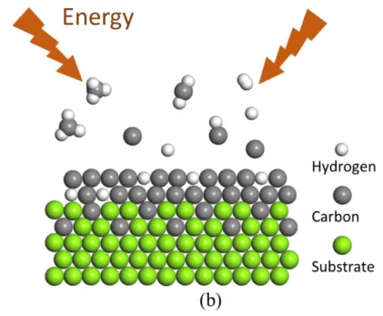
Fig. 2-1 Schematic diagram of ion implantation system (a) and IBED process (b)
2.1.2 Deposition of DLC films on different substrates
31
mix into the surface. Then, an alloyed bond layer is formed to promote adhesion of the film. Film–substrate adhesion is achieved without the external application of heat, and processing temperatures can be held below 93°C (200°F); therefore, no physical dimensions are produced [2]. Accordingly, the primary advantage of IBED is selective surface modification, which enables a series of beneficial surface property modifications without detrimentally affecting the bulk properties [3].
32
and a ballistically bonded zone, ie a permeation layer. In the IBED process, high-energy ions mix the initial atom layers of the film material into the surface being coated. It forms an alloyed bond layer which improves coating adhesion and allows coatings to be applied to virtually any substrate without an intermediate layer. The coating grows from alloyed layer and the high-energy ion flux controls the coating’s grain structure, density and residual stresses [1, 2].
The deposition of the DLC films was performed using IBED with CH4 and H2 sources.
Before the deposition, the chamber was evacuated to a base pressure of 4×10⁻⁴ Pa to produce plasma discharge. Then, the CH4 and H2 mixture was injected into the chamber.
The ratio of CH4/H2 was 99:1,1:99 and 1:1. The chamber pressure changed as the gas
was injected; therefore, the chamber pressure was fixed at 0.8×10⁻³ Pa using the pressure valve. During the deposition process, the ion beam interacted with the substrate via the accelerator, which was generated from the CH4 and H2 mixture. For all the magnesium
alloy samples, the current and deposition time were fixed at 40 mA and 4 h, respectively. Accelerating voltages of 6 and 9 kV and total gas flows of 3, 6, and 9 sccm were applied. For the stainless steel and titanium samples, the anode, accelerating voltage, current and gas flow was fixed at 40 mA, 10 kV, 2.5 mA and 0.4~0.5 sccm, respectively. Deposition time of 6 and 12 hrs were applied. Finally, the DLC coating with high adhesion was deposited. All the samples were cooled down inside the chamber after processing. The detailed experimental conditions are listed in Table 2-1.
Table 2- 1 Parameters for different processing conditions
(a) Mg
33 Gas flow (sccm) 3 9 6 Accelerating Voltage (kV) 6 6 6 9 9 9 6 6 6 (b) SUS316L Ti Gas ratio (CH4/H2) 1:1 1:1 1:0 1:0 1:1 1:1 1:0 1:0 Time (hrs) 6 12 6 12 6 12 6 12
2.2 Experimental analysis methods
2.2.1 Raman analysis
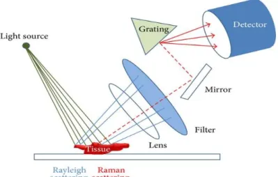
Schematic presentation of Raman spectroscopy instrument is shown in figure 2-2. When excitation light irradiates (green line), Rayleigh scattering (blue line) and Raman scattering (red dotted line) are released. Rayleigh scattering is filtered, and pure Raman scattering is detected [5].
34
Raman spectroscopy is mainly used to identify molecular structures and materials. Because of its high resolution to various carbon isomers, Raman spectroscopy is widely used to identify the structure of diamond, graphite, diamond-like and carbon nanotubes [6, 7]. It is a traditional, non-destructive means of analyzing carbon structures. The principle of Raman spectroscopy is that photons collide with the extranuclear electrons of matter, and use the information obtained by elastic scattering to analyze the structure of matter. When a high-frequency v0 monochromatic laser beam hits a substance molecule,
the frequency of the partially scattered light is different from the frequency of the incident light. The energy of the scattered light is h(v0-v1) or h(v0+v1), The lost energy or obtained
energy hv1 is equivalent to the vibration energy. This effect is called the Raman effect and
the resulting spectrum is called Raman spectroscopy. hv1 is called Raman shift. The
Raman spectrum gives the structure of the near surface of the carbon material. In this paper the detailed bonding structure of the DLC film was analyzed using Raman spectroscopy (NRS-4100) with a laser wavelength of 532.0 nm, spot size of Φ34 µm, and laser power of 0.03 mW.
2.2.2 Micromorphology analysis
35
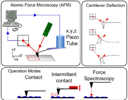
intermittent contact mode where the cantilever is oscillated near resonance and constant amplitude is maintained. The AFM is also capable of force spectroscopy measurements.
Fig. 2- 3 Schematic diagram of AFM analysis
36
ion beam (FIB) with a JIB-4500 Multi Beam system.
Fig. 2- 4 Schematic diagram of EPMA
The element compositions of cross-section polished with diamond paste (0.05 µm) were determined by an Electron probe microanalysis (EPMA) JXA-8900R. EPMA works by bombarding a micro-volume of a sample with a focused electron beam (typical energy = 5-30 keV) and collecting the X-ray photons thereby emitted by the various elemental species.
EPMA is a fully qualitative and quantitative method of non-destructive elemental
analysis of micron-sized volumes at the surface of materials, with sensitivity at the level of ppm. Routine quantification to 1% reproducibility is obtained over several days. It is the most precise and accurate micro-analysis technique available and all elements from B to U and above can be analyzed.
EPMA is fully compatible with routine analysis sessions, with easy and direct
37
Determination of thickness and elemental composition from nm to mm thick layers
in stratified materials is possible.
EPMA provides much better results than standard SEM/EDS systems. Because of the internal properties of WDS, the general sensitivity, analysis of light elements and risks of erroneous interpretation of qualitative spectra are all superior with EPMA. Spectral resolution and detector dead time are much better than EDS (Energy Dispersive Spectroscopy). The excitation beam regulation system and sophisticated sample stage capabilities guarantee that this technique provides outstanding stability and measurement repeatability.
The carbon element concentration distribution of DLC film-coated SUS316L were determined by EPMA. The sample to be analyzed was bombarded by an electron beam which would emit x-rays with wavelengths characteristic to specific elements. Then the concentration distribution and diffusivities of elements could be obtained accurately by EPMA mapping [11, 12].
2.2.3 XPS analysis
38
combining XPS measurements with ion milling (sputtering) to characterize thin film structures. The information XPS provides about surface layers or thin film structures is important for many industrial and research applications where surface or thin film composition plays a critical role in performance including: nanomaterials, photovoltaics, catalysis, corrosion, adhesion, electronic devices and packaging, magnetic media, display technology, surface treatments, and thin film coatings used for numerous applications.
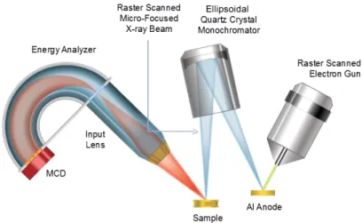
Fig. 2- 5 Schematic diagram of XPS analysis
XPS is typically accomplished by exciting a samples surface with mono-energetic Al kα x-rays causing photoelectrons to be emitted from the sample surface. An electron energy analyzer is used to measure the energy of the emitted photoelectrons. From the binding energy and intensity of a photoelectron peak, the elemental identity, chemical state, and quantity of a detected element can be determined. Schematic presentation of XPS spectroscopy instrument is shown in figure 2-4.
39
instruments, a finely focused x-ray beam is scanned to create secondary electron images for sample viewing and point spectra or images for compositional analysis. The size of the x-ray beam can be increased to support the efficient analysis of larger samples with homogeneous composition. In contrast to SEM/EDS which has a typical analysis depth of 1-3 µm, XPS is a surface analysis technique with a typical analysis depth of less than 5 nm and is therefore better suited for the compositional analysis of ultra-thin layers and thin microscale sample features.
40 2.2.4 TEM analysis
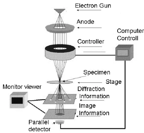
Transmission electron microscopy (TEM) is an imaging technique where a beam of electrons is transmitted through a specimen, thereby casting an image is formed, magnified and directed to appear either on a flurorescent screen or layer of photographic film or to be detected by a sensor such as a CCD camera. The first practical transmission electron microscope was built by Albert Prebus and James Hillier at the university of Toronto in 1938 using concepts developed earlier by Max Knoll and Ernst Ruska. The most common use of transmission electron microscopy in nanomaterials is to measure the distribution of particle size as well as the morphology of supported or unsupported active materials. It is also used to detect the defect structures in case of some electronic materials. The specimens for TEM should be very thin so that the electron beam may penetrate through the sample and should be able to withstand the high vacuum present inside the instrument. Fig. 2-6 shows the schematic of the working of a transmission electron microscope [16]. The FIB equipment we used for preparing TEM samples. As an initial work of specimen preparation, the sample was cut into a size of 10mm×10mm. After thinning the slice thickness to about 30μm, a 1.5mm×1.5mm foil was cut off and glued on a Mo grid. Then the sample was further cut by FIB. The sample was milled into stair-step shape initially and finally it was milled down to a thickness of about 0.1 μm.
41
magnetic lenses to form a pattern of spots; each spot corresponds to a specific atomic spacing (a plane). This pattern can then yield information about the orientation, atomic arrangements and phases present in the area being examined [17, 18]. From the selected area diffraction pattern, d-spaces corresponding to the rings could be calculated by the following equation:
Rd=Lλ (2-1)
where R is the distance of any reflections from the center of pattern, d is the interplanar spacing, L is the effective camera length, λ is the wave length of the incident beam.
Fig. 2- 5 Schematic diagram of TEM analysis
42
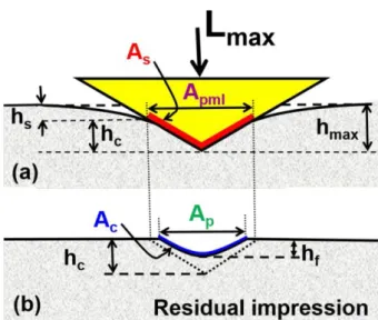
In the nanoindentation test [19, 20], the indenter is pushed into the surface of the sample producing both elastic and plastic deformation of the material (Fig. 2-7). The first difference with macro- or micro-indentation tests is that, in the nanoindentation machines, the displacement h and the load L are continuously monitored with high precision, as schematically shown in Fig. 2-8. During the nanoindentation process, the indenter will penetrate the sample until a predetermined maximum load Lmax is reached, where the
corresponding penetration depth is hmax. When the indenter is withdrawn from the sample,
the unloading displacement is also continuously monitored until the zero load is reached and a final or residual penetration depth hf is measured. The slope of the upper portion of
the unloading curve, denoted as S = dL/dh, is called the elastic contact stiffness [21, 22]. In nanoindentation, the hardness of the material is defined as H = L/Apml, where Apml is the projected area of contact at the maximum load. In this method, the maximum load ranges between few l µN and about 200 mN, while penetrations will vary from few nm to about few µm [22, 23].
43
Fig. 2- 7 Load–unload during nanoindentation
2.4 Corrosion performance analysis
2.4.1 Corrosion test
The DLC films-coated stainless steel and titanium substrates were corroded by potentiostatic polarizations in a 0.5mol/L sulfuric acid solution at 90 ℃, 0.8V for 168 hrs. The schematic diagram of corrosion test was showed in Fig. 2-9. The sample was cut to a size of 20 × 20 mm2 by a circular saw after the deposition and then sealed with epoxy resin and exposed one end with an area of 10 × 10 mm2. The metal ions in sulfuric acid
44
Fig. 2- 8 Schematic diagram of corrosion test
Fig. 2- 9 Schematic diagram of ICP analysis
45
It is a flame technique with a flame temperature in a range from 6000 to 10000 K. The intensity of this emission is indicative of the concentration of the element within the sample. The ICP-AES is composed of two parts: the ICP and the optical spectrometer. The ICP torch consists of 3 concentric quartz glass tubes. The output or "work" coil of the radio frequency (RF) generator surrounds part of this quartz torch. Argon gas is typically used to create the plasma. Examples of the application of ICP-AES include the determination of metals in wine, arsenic in food, and trace elements bound to proteins.
2.4.2 Corrosion behavior DLC films
46
Fig. 2- 11 Mechanism of localized corrosion developing on metal in a solution containing oxygen
Fig. 2- 12 Heavily sensitized microstructure
47
48
References
[1] A. H. Deutchman and R. J. Partyka, "Ion beam enhanced deposition," Advanced
materials & processes, vol. 161, no. 7, pp. 33-35, 2003.
[2] A. H. Deutchman and R. J. Partyka, "Industrial Scale Ion Beam Enhanced Deposition (IBED) Processing System," in Proceedings: ASM International Su
Proceedings: ASM International Surface Engineering Congress, 2002, pp. 1-9.
[3] P. Sioshansi and E. J. Tobin, "Surface treatment of biomaterials by ion beam processes," Surface and coatings Technology, vol. 83, no. 1-3, pp. 175-182, 1996. [4] J. Robertson, "Diamond-like amorphous carbon," Materials science and
engineering: R: Reports, vol. 37, no. 4-6, pp. 129-281, 2002.
[5] D. A. Long and D. Long, Raman spectroscopy. McGraw-Hill New York, 1977. [6] A. C. Ferrari, "Raman spectroscopy of graphene and graphite: disorder, electron–
phonon coupling, doping and nonadiabatic effects," Solid state communications, vol. 143, no. 1-2, pp. 47-57, 2007.
[7] D. S. Knight and W. B. White, "Characterization of diamond films by Raman spectroscopy," Journal of Materials Research, vol. 4, no. 2, pp. 385-393, 1989. [8] H.-J. Butt, B. Cappella, and M. Kappl, "Force measurements with the atomic force
microscope: Technique, interpretation and applications," Surface science reports, vol. 59, no. 1-6, pp. 1-152, 2005.
[9] M. Tortonese, R. Barrett, and C. Quate, "Atomic resolution with an atomic force microscope using piezoresistive detection," Applied physics letters, vol. 62, no. 8, pp. 834-836, 1993.
[10] S. Alexander et al., "An atomic‐resolution atomic‐force microscope implemented using an optical lever," Journal of Applied Physics, vol. 65, no. 1, pp. 164-167, 1989.
[11] J. H. Kim, J. T. Yeom, J. K. Hong, S. Y. Shim, S. G. Lim, and N. K. Park, "Effect of scandium on the hot extrudability of 7075 aluminum alloy," Metals and
Materials International, vol. 16, no. 4, pp. 669-677, 2010.
[12] W. Lengauer and M. Bohn, "Thermochemical basis of the preparation of well-defined transition metal carbide, nitride and carbonitride reference materials for electron-probe microanalysis (epma)," in Solid State Phenomena, 2018, vol. 274, pp. 20-42: Trans Tech Publ.
49
the ESCA Molecule and Surface‐to‐Bulk XPS Shifts," ChemPhysChem, vol. 19, no. 2, pp. 169-174, 2018.
[14] J. Moulder, "The impact of the scanning XPS microprobe on industrial applications of X-ray photoelectron spectroscopy," Journal of Electron
Spectroscopy and Related Phenomena, 2018.
[15] M. Schmal and C. A. C. Perez, "X-Ray Photoelectron Spectroscopy (ESCA: XPS/ISS)," in Heterogeneous Catalysis and its Industrial Applications: Springer, 2016, pp. 251-266.
[16] B. Baruwati, "Studies on the Synthesis, Characterization, Surface Modification and Application of Nanocrystalline Nickel Ferrite," INDIAN INSTITUTE OF CHEMICAL TECHNOLOGY HYDERABAD, 2007.
[17] P. Stadelmann, "Image analysis and simulation software in transmission electron microscopy," Microscopy and microanalysis, vol. 9, no. S03, pp. 60-61, 2003. [18] N. Tanaka, Scanning transmission electron microscopy of nanomaterials. World
Scientific, 2015.
[19] E. Broitman, "Indentation hardness measurements at macro-, micro-, and nanoscale: a critical overview," Tribology Letters, vol. 65, no. 1, p. 23, 2017. [20] K. Liu, M. Ostadhassan, and B. Bubach, "Applications of nano-indentation
methods to estimate nanoscale mechanical properties of shale reservoir rocks,"
Journal of Natural Gas Science and Engineering, vol. 35, pp. 1310-1319, 2016.
[21] E. Berkovich, "Three faceted diamond pyramid for micro-hardness testing,"
Industrial Diamond Review, vol. 11, no. 127, p. 129, 1951.
[22] W. C. Oliver and G. M. Pharr, "An improved technique for determining hardness and elastic modulus using load and displacement sensing indentation experiments," Journal of materials research, vol. 7, no. 6, pp. 1564-1583, 1992. [23] W. C. Oliver and G. M. Pharr, "Measurement of hardness and elastic modulus by
instrumented indentation: Advances in understanding and refinements to methodology," Journal of materials research, vol. 19, no. 1, pp. 3-20, 2004. [24] S. Greenfield, "Inductively coupled plasma-atomic emission spectroscopy
(ICP-AES) with flow injection analysis (FIA)," Spectrochimica Acta Part B: Atomic
Spectroscopy, vol. 38, no. 1-2, pp. 93-105, 1983.
[25] H. Kokawa, M. Shimada, M. Michiuchi, Z. Wang, and Y. Sato, "Arrest of weld-decay in 304 austenitic stainless steel by twin-induced grain boundary engineering," Acta Materialia, vol. 55, no. 16, pp. 5401-5407, 2007.
51
Chapter 3 Surface characteristics and tribological
properties of DLC films on magnesium alloy
3.1 Chemical bonding structure of DLC films
Raman spectroscopy is generally used to analyze the detailed bonding structure of DLC coatings. Raman spectroscopy has the advantages of being non-destructive and allowing easy examination of the low-wavenumber region.
Fig. 3- 1 The typical Raman spectrum fitted by the Gaussian at 6 sccm and 6 kV.
52
Fig. 3- 3 The ID/IG of DLC films deposited at different gas ratio, flow rate and accelerating voltage.
In general, the Raman spectra of the DLC films could be fitted by two Gaussian peaks: the G-peak (located at approximately 1580 cm−1) and D-peak (located at approximately 1350 cm−1). The G-peak (graphite) originates from bond stretching of sp2 atoms in both aromatic rings and chains, and the D-peak (disorder) originates from the breathing modes of sp2 atoms in aromatic rings [1, 2]. The sp2 site consists of two π orbitals and two σ
orbitals, whereas the sp3 site consists of four σ orbitals. The π state is more polarizable than the σ state because of the lower energy of the π state. Therefore, the Raman spectra are dominated by the sp2 site, which has a 50–230 times larger Raman cross-section than the sp3 site [3]. Fig. 3-1 displays a typical Raman spectrum for the DLC coating deposited
at 6 sccm/ 6 kV. The spectrum consists of a widely asymmetric Raman scattering band in the range of 1000–2000 cm−1, which is a typical characteristics of DLC coatings [4].
The intensity ratio of the D-peak to G-peak (ID/IG) and the position of the G-peak were
used to characterize the DLC films [5, 6]. A shift of the G-peak position to higher wavenumbers and an increase of the intensity ratio ID/IG are consistent with an increase
53
at different gas ratio, flow rate and accelerating voltages. Using of the Gaussian fitting method, the ID/IG ratios of the DLC films with different processing conditions were
presented in Fig. 3-3. The ID/IG ratios increased and the G-peak position shifted toward
higher wavenumber with increasing accelerating voltage at CH4/H2 ratio of 99:1, and
ID/IG decreased and the G-peak position shifted toward lower wavenumber with
increasing gas flow rate at 6 kV. ID/IG decreased and the G-peak position shifted toward
lower wavenumber when the gas flow rate increased from 3 sccm to 6 sccm at CH4/H2
ratio of 1:99. The ID/IG and G-peak position were lower for the deposition at CH4/H2=99:1
than at CH4/H2=1:99. For instance, at CH4/H2 ratio of 99:1, a gas flow rate of 9 sccm and
accelerating voltages of 6 and 9 kV, the G-peak position was 1534.2 and 1546.2 cm−1 as shown in Figure 3. The corresponding ID/IG ratios were 1.25 and 2.21 respectively shown
on Figure 4. For the accelerating voltage of 6 kV and gas flow rates of 3 and 9 sccm, the ID/IG ratios were 2.12 and 1.25, respectively. Thus, the ID/IG ratio of the DLC film
deposited at 6 kV was lower than that deposited at 9 kV. The ID/IG ratio decreased with
decreasing CH4/H2 ratio from 99:1 to 1:99, The ID/IG ratio decreased to a minimum value
of 0.62 at 6 sccm/6 kV.
Usually, an increase in the G-peak position correspond to an increase in the sp3 content.
The ID/IG values are related to sp2 clustering and increase as the sp2 fraction increases [5].
The G-peak position and ID/IG ratio increase with increasing sp2/sp3 ratio in hydrogenated
amorphous DLC films [8]. If the sp2 type is predominant, the film will be softer and the DLC film structure will be more disordered. The nanostructure is transformed from a typical three-dimensional diamond-like crosslinking structure to a two-dimensional graphite-like structure. As the fraction of sp3-hybridized C–C bonding increases, the films