特 性 資 料
Characteristics Data
クリーンソルダー ソルダークリーム NP303-LHGQ-27KR
CLEAN SOLDER SOLDER CREAM NP303-LHGQ-27KR
株式会社 ニホンゲンマ
技 術 部
NIHON GENMA MFG.CO.,LTD
TECHNICAL DEPARTMENT
1.特徴 Features ・・・・・・・・・・・・・・・・・・・・・・・・・・・・・・・・・・・・・・・・・・・・・・ 2.一般特性 Characteristics ・・・・・・・・・・・・・・・・・・・・・・・・・・・・・・・・・・・・・・・・ 3.詳細データ Data ・・・・・・・・・・・・・・・・・・・・・・・・・・・・・・・・・・・・・・・・・・・・・・・・・ 3-1 NP303はんだ組成 NP303 composition ・・・・・・・・・・・・・・・・・・・・・・・・・・・・・・ 3-2 NP303はんだ特性 NP303 characteristics ・・・・・・・・・・・・・・・・・・・・・・・・・・・ 3-3 フラックス含有量 Flux content ・・・・・・・・・・・・・・・・・・・・・・・・・・・・・・・・・・・ 3-4 粘度(流動特性) Viscosity (Fluidity characteristic) ・・・・・・・・・・・・・・・・・・・・ 3-5 ハライド系活性剤含有量試験 Halide content ・・・・・・・・・・・・・・・・・・・・・・・ 3-6 広がり率 Spreading ratio ・・・・・・・・・・・・・・・・・・・・・・・・・・・・・・・・・ 3-7 ふっ化物含有試験 Fluoride content test ・・・・・・・・・・・・・・・・・・・・・・・・・・・・・・ 3-8 絶縁抵抗試験 Insulation resistance ・・・・・・・・・・・・・・・・・・・・・・・・・・ ・・ ・ 3-9 銅鏡腐食試験 Copper mirror corrosion test ・・・・・・・・・・・・・・・・・・・・・・ ・ 3-10 フラックス残渣の銅板腐食試験 ・・・・・・・・・・・・・・・・・・・・・・・・・・・・・・・・・・・・・・・
Corrosivity test of flux residue on Cu plate
3‐11 印刷時のだれ試験 Slump-in-print ・・・・・・・・・・・・・・・・・・・・・・・・・・・・・・・・・・ 3‐12 加熱時のだれ試験 Slump-in-heat ・・・・・・・・・・・・・・・・・・・・・・・・・・・・・・・・・・ 3‐13 粘着性試験 Tackiness ・・・・・・・・・・・・・・・・・・・・・・・・・・・・・・・・・・・・・ 3‐14 ぬれ効力試験 Wetting effect ・・・・・・・・・・・・・・・・・・・・・・・・・・・・・・・・・・ 3‐15 ソルダボール試験 Solder ball ・・・・・・・・・・・・・・・・・・・・・・・・・・・・・・・・・・・・ 3‐16 マイグレーション試験 Migration ・・・・・・・・・・・・・・・・・・・・・・・・・・・・・・・・・・・・・・ 4. 推奨リフロープロファイル ・・・・・・・・・・・・・・・・・・・・・・・・・・・・・・・・・・・・・・・・・・・・・・・・・・
Recommended reflow profile
5. 使用上の注意事項 ・・・・・・・・・・・・・・・・・・・・・・・・・・・・・・・・・・・・・・・・・・・・・・・・・・・・・・・ Caution in use
目 次
INDEX
T141127A 2/13 3 3 4 4 4 5 5 6 6 6 7 7 8 9 9 10 10 11 11 12 131.特徴
Characteristic
・大気リフローではんだ付可能な低ハロゲンのソルダークリームです
・This solder cream is low-halide, and it is possible with soldering at air re-flow.
2. 一般特性 Characteristics
表1 一般特性表 Table 1 Characteristics list
項目 Item 特性 Characteristics 代表値 Representative value 試験方法 Test method はんだ組成 Solder composition Sn3.0Ag0.5Cu Sn3.0Ag0.5Cu -
融点(℃) Melting point (℃) 217-221 217-221 DSC
粉末粒径(μm)及び形状
Solder powder particle size (μm) and shape
38-22 Spherical
38-22
Spherical JIS Z 3284 1 フラックス含有量(wt%) Flux content (wt%) 11.0±0.3 11.08 JIS Z 3197 8.1.2
粘度(Pa.s) Viscosity(Pa.s) 200 ±20 193.5 JIS Z3284 6 Malcom PCU-2, 5, 205 チクソ比 TI index 0.55±0.10 0.595 ハロゲン含有量(ppm) Halogen content(ppm) ≦1500 214ppm *1 広がり率(%) Spreading ratio (%) 75%以上 75% min 75.2% JIS Z 3197 8.3.1.1 ふっ化物含有試験 Fluoride content ふっ化物なし No fluoride ふっ化物なし No fluoride JIS Z 3284 2 絶縁抵抗(Ω) Insulation resistance (Ω) 40℃90% 1.0×10¹¹以上 1.0×10¹¹ min 1.71×10¹¹ JIS Z 3284 3 (1000Hr) 85℃85% 5.0×10⁸以上 5.0×10⁸min 8.32×10⁸ 銅鏡腐食試験
Copper mirror corrosion test
腐食なし No corrosion
腐食なし
No corrosion JIS Z 3197 8.4.2 フラックス残渣の銅板腐食性試験
Corrosivity test of flux residue on Cu plate
腐食なし No corrosion 腐食なし No corrosion JIS Z 3284 4 印刷ダレ Slump-in-print 0.2mmブリッジなし No bridge in 0.2mm 0.2mmブリッジなし No bridge in 0.2mm JIS Z 3284 7 加熱ダレ Slump-in-heat 0.3mm ブリッジなし No bridge in 0.3mm 0.2mm ブリッジなし No bridge in 0.2mm JIS Z 3284 8 (180℃) 粘着性 Tackiness 0 hr 1.0 N min 1.36N JIS Z 3284 9 24 hr 1.0 N min 1.22N ぬれ効力試験 Wetting effect (copper plate)
度合い1-3 Class 1-3 度合い2 JIS Z 3284 10 ソルダーボール試験 Solder ball 度合い1-3 Class 1-3 度合い1 JIS Z 3284 11 マイグレーション Migration 発生なし Not occur 発生なし
Not occur JIS Z 3284 14
*1 測定方法:フラスコ燃焼法+イオンクロマトグラフ測定 ハロゲン含有量・・・塩素:900ppm以下、臭素:900ppm以下、合計:1500ppm以下
Test method: Flask combustion method+Ion chromatography
Halogen content・・・Cl (chlorine): 900ppm max、Br (bromine): 900ppm max、the total halogen content: 1500ppm max
3-1. NP303はんだ組成 NP303 composition
試験結果:表2に示します。 Test result :As shown in Table 2.
弊社品番 Product name はんだの組成 Solder Composition 溶融温度(℃) Melting point(℃) 引張強度(MPa) Tensile Strength(Mpa) 伸び(%) Elongation(%) NP303 96.5Sn3.0Ag0.5Cu 217-221 37 33 表2. NP303はんだ組成 Table 2. NP303 composition 3-2. NP303はんだ特性 NP303 characteristics
試験結果:表3に示します。 Test result :As shown in Table 3.
表3. NP303はんだ特性 Table 3. NP303 characteristics 3 詳細データ Data Sn Ag Cu 規格値 残部 3.0±0.2 0.5 ±0.05 Standard Rest 分析値 残部 3.03 0.502 Analysis Rest Pb Sb Bi Au In Al As Cd Fe Ni Zn 規格値 0.05 0.10 0.10 0.05 0.10 0.001 0.03 0.002 0.02 0.01 0.001 以下 以下 以下 以下 以下 以下 以下 以下 以下 以下 以下
Standard max max max max max max max max max max max
分析値
0.021 0.004 0.000 0.000 0.003 0.000 0.003 0.000 0.002 0.001 0.000
Analysis
引張試験条件 (Tension Test Condition) ・引張試験片形状(Shape of the Test Piece)
・引張速度 5.0mm/min( Tension speed・・・5.0mm/min)
10 100 1000 1 10 100 流動特性 Fluidity characteristic 測定時間(分) Measuring time(min) 3分 min 6分 min 3分 min 3分 min 3分 min 1分 min 1分 min 1分 min 回転数(r.p.m) Rotation speed 10 3 4 5 10 20 30 10 粘度値(PaS) Viscosity 193.5 427.3 355.7 306.1 198.8 130.5 108.5 193.3 測定結果 Test result 粘度(Pgs Viscosity 193.5 チクソトロピ‐指数 TI 0.595 非回復率 Non-recovery rate 2.77
3-4. 粘度(流動特性) Viscosity (Fluidity characteristic)
試験方法:JIS Z 3284 6 Test method: Based on JIS Z 3284 6 試験機器:MALCOM PCU-2,5,205 Test machine: MALCOM PCU-2, 5, 205
試験結果:図1及び表5に示します。 Test result : As shown in Fig. 1 and Table 5.
図1 流動特性 Fig. 1 Fluidity characteristic
表5 流動特性 Table 5 Fluidity characteristic 回転数(rpm) Rotation speed(rpm) 粘度( P as ) V is co si ty( Pas ) 試験回数 Test times
1
2
3
4
5
平均 Average 結果数値(Wt%) Test value(Wt%)11.05
11.13
11.01
11.10
11.09
11.08
3-3 . フラックス含有量 Flux content試験方法:JIS Z 3197 8.1.2 Test method: Based on JIS Z 3197 8.1.2 試験結果:表4に示します。 Test result :As shown in Table 4.
表4. フラックス含有量(wt%) Table 4. Flux content (wt%)
3-6. 広がり率 Spreading ratio
試験方法:JIS Z 3197 8.3.1.1 Test method: Based on JIS Z 3197 8.3.1.1. 試験結果:図2、表7に示します。 Test result : As shown in Fig. 2 and Table 7.
試験回数 test times
1
2
3
4
5
平均 Average 広がり率(%) Spreading ratio(%)75.2
75.1
75.3
75.5
75.1
75.2
図2 試験片 Fig. 2 Test piece
表7 広がり率 Table 7 spreading ratio
3-7. ふっ化物含有試験 Fluoride content test
試験方法:JIS Z 3284 2 Test method: Based on JIS Z 3284 2 試験結果:図3に示します。 Test result : As shown in Fig. 3
ふっ化物なし No fluoride
図3. ふっ化物含有試験 Fig. 3 Fluoride content test 3-5.ハロゲン含有量試験 Halide content
試験方法:フラスコ燃焼法+イオンクロマトグラフ測定
Test method: Flask combustion method+Ion chromatography
試験結果:表6に示します。 Test result : As shown in Table 6.
試験回数 Test times
1
2
3
4
5
平均 Average 試験結果(ppm) Test value (ppm)220
201
255
190
205
214
表6. ハライド含有量 Table 6. Halide content (ppm) T141127A 6/13
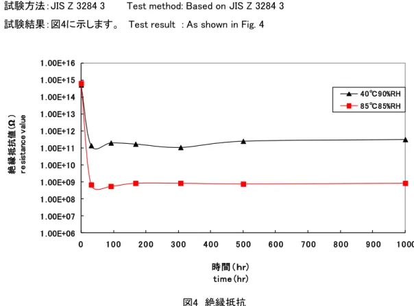
3-8. 絶縁抵抗試験 Insulation resistance
試験方法:JIS Z 3284 3 Test method: Based on JIS Z 3284 3 試験結果:図4に示します。 Test result : As shown in Fig. 4
図4 絶縁抵抗
Fig. 4 Insulation resistance
3-9. 銅鏡腐食試験 Copper mirror corrosion test
試験方法:JIS Z 3197 8.4.2 Test method: Based on JIS Z 3197 8.4.2 試験結果:図5に示します。 Test result : As shown in Fig. 5
図5 銅鏡腐食試験
Fig. 5 Copper mirror corrosion test 腐食なし No corrosion 1 . 00E+06 1 . 00E+07 1 . 00E+08 1 . 00E+09 1 . 00E+10 1 . 00E+11 1 . 00E+12 1 . 00E+13 1 . 00E+14 1 . 00E+15 1 . 00E+16 0 1 0 0 2 0 0 3 0 0 4 0 0 5 0 0 6 0 0 7 0 0 8 0 0 9 0 0 1 0 00 絶 縁 抵抗 値( Ω ) re si st an c e v al ue 時間(hr) time (hr) 40℃90%RH 85℃85%RH T141127A 7/13
下 Bottom 上 lid 腐食なし No corrosion 腐食なし No corrosion 3-10. フラックス残渣の銅板腐食試験 Corrosivity test of flux residue on Cu plate
試験方法:JIS Z 3284 4 Test method: Based on JIS Z 3284 4.
試験結果:図6に示します。 Test result : As shown in Fig. 6, no corrosion is occurred.
図6 フラックス残渣の銅板腐食試験
Fig.6 Corrosivity test of flux residue on Cu plate
フラックスの 飛散箇所 Spatter of flux T141127A 8/13 9 6 H r 初 期 I n i t i a l 拡 大 写 真 E n l a r g e d p h o t o
3-11. 印刷時のだれ試験 Slump-in-print
試験方法:JIS Z 3284 7 Test method: Based on JIS Z 3284 7 試験結果:図7に示します。 Test result : As shown in Fig. 7
図7 印刷ダレ結果(印刷後1時間放置) Fig. 7 Slump-in-print (Left for 1 hr after print) 1.5×0.7mm pattern 1.5×0.3mm pattern 0.2mmブリッジなし No bridge in 0.2mm 0.2mmブリッジなし No bridge in 0.2 mm 3-12. 加熱時のだれ試験 Slump-in-heat
試験方法:JIS Z 3284 8 Test method: Based on JIS Z 3284 8 加熱条件:オーブン180℃、60秒間 Heating condition: oven 180℃, 60sec. 試験結果:図8に示します。 Test result : As shown in Fig. 8
図8 加熱ダレ結果(180℃ 60秒加熱後)
Fig. 8 Slump-in-heat(After heating at 180℃ for 60sec) 1.5×0.7mm pattern 1.5×0.3mm pattern 0.2mmブリッジなし No bridge in 0.2mm 0.2 mmブリッジなし No bridge in 0.2 mm T141127A 9/13 0.2 0.4 0.6 0.3 0.5 0.7 0.2 0.3 0.4 0.5 0.2 0.4 0.6 0.3 0.5 0.7 0.2 0.3 0.4 0.5
3-13. 粘着性試験 Tackiness
試験方法:JIS Z 3284 9 Test method: Based on JIS Z 3284 9 放置環境:25±2℃、50±10%RH Left condition: 25±2℃, 50±10%RH 試験結果:図9に示します。 Test result: As shown in Fig. 9
図9 粘着性試験結果 Fig. 9 Tackiness test
銅板 Copper plate 黄銅板 Brass plate
度合い 2 Class 2 度合い 2 Class 2 3-14. ぬれ効力試験 Wetting effect
試験方法:JIS Z 3284 10 Test method: Based on JIS Z 3284 10 試験結果:図10に示します。 Test result : As shown in Fig. 10
図10 ぬれ効力試験結果 Fig. 10 Wetting effect
0 0.2 0.4 0.6 0.8 1 1.2 1.4 1.6 0 4 8 12 16 20 24 粘着力( N) ta c k in e s s ( N) 時間(hr) time (hr) T141127A 10/13
3-15. ソルダボール試験 Solder ball
試験方法:JIS Z 3284 1 Test method: Based on JIS Z 3281 11 放置環境:表8に示します。 Ambient: As shown in Table 8. 試験結果:図11に示します。 Test result : As shown in Fig. 11
放置環境 Environmental condition 放置時間(時間) Leaving time (hr) 25±2℃, 50±5%RH 24 図11 ソルダーボール試験結果 Fig. 11 Solder ball
初期 Initial 24hr
初期と24時間放置後の差は見られません No difference between Initial and 24hr
表8 試験片放置環境 Table 8 Environmental condition
はんだの凝集度合判定 1 Class 1 はんだの凝集度合判定 1 Class 1 40℃/90 %RH 85℃/85 %RH 3-16. マイグレーション 試験 Migration
試験方法:JIS Z 3284 14 Test method: Based on JIS Z 3284 14
試験結果:図12に示しているように、マイグレーションの発生がありません。
Test result : As shown in Fig. 12, no migration occurred.
図12 マイグレーション Fig. 12 Migration test マイグレーション発生なし No migration -極 +極 -極 -極 +極 -極 マイグレーション発生なし No migration T141127A 11/13
0
50
100
150
200
250
300
0
20
40
60
80
100
120
140
160
180
200
220
240
260
280
T em p er a tur e ( ℃ ) 温度150~190℃ 130sec
30sec50sec
190℃
220℃
150℃
250℃
235℃
60sec
100sec
40sec ・プリヒート プリヒート温度までの昇温速度は1~10℃/秒でご使用ください。急激な温度上昇はソルダ‐クリームのダレ性を悪 化させる場合があります。また、基板上の温度バラツキ(⊿t)を少なくするため、プリヒート温度を150℃から190℃ 付近で、プリヒート時間を60~130秒でご使用ください。プリヒート温度が低く、時間が短いと基板上の温度ばらつき (⊿t)が大きくなり、未溶融が発生する場合があります。またプリヒート温度が高く、時間が長いとプリヒート中に ソルダークリームの活性力が失われ、未溶融が発生する場合があります。 ・Pre-heatUse rising up rate of pre-heat temperature at 1-10℃/sec. Rapid rising may cause slump of solder cream. To reduce temperature dispersion (⊿t) on the PCB, use pre-heat temperature at 150-190℃, and pre-heat time for 60-130sec. In case of lower temperature and shorter time, the temperature dispersion (⊿t) on the PCB will be larger. Moreover, in case of higher temperature and longer time, activity of flux will be lost and non-melting may occur. ・本加熱 ピーク温度は部品の耐熱性を考慮して、低い温度(235℃)で長い時間保持してください。リフロー炉の性能上、本加熱 を保持することが困難な場合、通常より高い温度(250℃)で部品の耐熱保証温度をご確認の上ご使用ください。 溶融時間は220℃以上の時間が30秒以上になるように設定してください。 ・Reflow peak
Recommended to maintain longer period in 235℃. When there is situation that unable to maintain, we recommend to maintain shorter period in 250℃ but please check component assurance temperature and period before you use. Please set up the reflow so that the melting temperature time of solder is as follows.
Temperature -> not less than 220 ℃ Time -> 30 seconds or more
・冷却
冷却をゆるやかにすると部品のずれ・立ちや、接合強度の低下を招くことがあります。逆に速すぎると、サーマルショック により、部品が破損することがあります。5~10℃/secで冷却して下さい。
・Cooling
Gentle cooling may slowly shift, standing of component, and reduce in joint strength. On the other hand, too fast cooling caused a component damage by thermal shock. Cooling speed should be set at 5-10℃/sec. *リフロープロファイルは、部品や基板の状態やリフロー炉の仕様により変わりますので、予め十分な試験を行って下さい。
*Reflow profile is depend on condition of component, specification of reflow furnace and PCB. Please conduct testing before the recommended.
4. 推奨リフロープロファイル
Recommended reflow profile
―― 上限 Max ―― 下限 Min ―― 推奨 Recommendation 10℃/sec 10℃/sec 5℃/sec 1℃/sec 1℃/sec 10℃/sec 8℃/sec 2℃/sec 2℃/sec 245℃ T141127A 12/13 時間(sec) Time(sec)
5. 使用上の注意事項
Caution in use
① 本製品は、はんだ付け以外の用途に使用しないで下さい。
Do not use this product for other purposes differently except soldering.
② 本製品を直接手で触れないようにして下さい。もし、付着した場合は、アルコール等の適当な溶剤で 拭き取った後、石鹸で洗って下さい。
Do not touch this product directly. In case of skin contact, wipe with tissue or cloth with alcohol or appropriate solvent then wash by soap water.
③ 本製品の使用時には、換気を充分に行い、蒸気を吸入しないようにして下さい。 Do not inhale fume generated from this product. Adequate ventilation is required.
④ 本製品の保管条件及び保証期間は、下記の通りです。保証期間内にご使用下さい。 冷蔵保管(10℃以下):3ヶ月
Recommended storing condition and quality guarantee period are as follows: Keep refrigerated (less than 10 degree) : 3 months from manufacturing date.
⑤ 本製品を室温に戻す場合は、急激な昇温を避けて、密閉状態のまま室温に放置(1~2時間程度) して行って下さい。
After took out from refrigerator, please keep it at room temperature for 1-2 hour. Please do not open the seal while it is cold.
⑥ 本製品の推奨使用環境は25±2℃,50±20%です。 この範囲外で使用される場合は、ソルダークリームの状態 や、はんだ付け性を確認の上、ご使用下さい。
Recommended use environment is 25±2℃,50±20% . If it is used outside of this range , check the state of the solder cream and solderability.
⑦ 印刷後、部品搭載までの放置時間は8時間程度です。
Optimum tack time after printing to mounting of components is about 24 hours.
⑧ 塩素系溶媒、ふっ素系溶媒、その他溶媒がソルダ‐クリームに混入すると印刷劣化、ソルダ‐ボール 発生の原因となりますので、印版の洗浄及び乾燥は充分注意して下さい。
Contamination by chlorinated or fluorinated solvents or other type of solvents will cause degrading of printability and solder ball. Please be careful in cleaning of stencil.
⑨ 本製品は消防法非危険物ですが、第4類第3石油類に該当する溶剤を使用しておりますので、 作業場所、保管場所で火気に充分注意して下さい。
This SOLDER CREAM contains flammable substance, so be careful and avoid exposure to excessive heat or fire when using in the workshop or during storage.