Liquid Metal Embrittlement in Resistance Spot Welding (Third Report) - Prediction of Residual Stress Distribution caused by Resistance Spot Welding with Material Mechanics Model -
6
0
0
全文
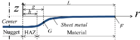
(2) Satoshi Hirose et al / International Journal of Automotive Engineering Vol.12, No.2(2021) It was assumed that through-thickness stress and circumferential strain do not occur in bending deformation. For the sake of simplicity, bending deformation was assumed not to occur in the nugget region totally constrained by the electrodes, and the electrode force was assumed not to produce throughthickness compressive stress. Bending deformation-induced radial strain r and circumferential strain are given in Eqs. (2) and (3), respectively.. from bending deformation-induced change dz in the throughthickness position in minute section dr. The term “V” is an adjustment parameter introduced for the simple consideration of the effect of large deformation and becomes unity when the deformation is assumed to be small. Equation (10) is derived from Eqs. (7) and (9).. ρ=− 𝜀𝑟 =. 𝜀𝜃. 𝜎𝑦∗. (𝑐 ∗. − 1) 𝜎𝜃 (1 − ) (𝜎𝑟 − ) ∗ 𝐸 2 𝜎𝑒𝑞. (𝑐 ∗ − 1) 𝜎𝑦∗ 𝜎𝑟 = (1 − ) (𝜎𝜃 − ) ∗ 𝐸 2 𝜎𝑒𝑞. (2). √3 𝜎 = √3𝜎𝜃 2 𝑟. (3). (4). (5). 3(𝑐 ∗ − 1) √3(𝑐 ∗ − 1) ∗ 𝜎 − 𝜎𝑦 𝑟 4𝐸 ∗ 2𝐸 ∗. (6). Accordingly, moment M produced in a given position is shown by Eq. (7).. 2√3𝐼 ∗ 𝜎𝑦∗ 3𝜌𝐸 ∗ 𝐼 ∗ 𝑀 = ∫ 𝜎𝑟 𝑧𝑑𝐴 = + 𝜑 4(𝑐 ∗ − 1) 𝑡∗ 𝐴 = 𝑀𝑁𝐻 + 𝑅𝑁𝐻 𝑟. 𝑀𝐴𝑁𝐻 =. 𝛽𝑈 − 𝛾𝑇 𝑔𝛽 − 𝑇 𝑁𝐻 𝛽 + 𝑖 + 𝑤 𝑁𝐻 (11) 𝛽𝑆 − 𝛼𝑇 𝛽𝑆 − 𝛼𝑇 𝛽𝑆 − 𝛼𝑇. 𝑀𝐵𝑁𝐻 =. 𝛾𝑆 − 𝛼𝑈 𝑆 − 𝑔𝛼 𝑁𝐻 𝛼 + 𝑖 − 𝑤 𝑁𝐻 (12) 𝛽𝑆 − 𝛼𝑇 𝛽𝑆 − 𝛼𝑇 𝛽𝑆 − 𝛼𝑇. (7). Where A is the cross-sectional area in the given position, z is the through-thickness position, I is the second moment of area, is the curvature, t is the sheet thickness, and r is the radial position when the boundary between the nugget region and the HAZ region is denoted by 0. The term is a variable that can become positive or negative depending on whether the radial strain is positive or negative, or is tensile or compressive. Variable changes with the forced displacement of the workpiece under electrode force. For example, assuming that the workpiece deflects downward without change in the deflection angle of the nugget region and that the sign of the curvature changes at point G (r = g) in the base metal region as shown in Fig. 1, variable can be written as follows:. φ = −1 (0 ≤ 𝑟 ≤ 𝑔) { φ = +1 (𝑔 ≤ 𝑟 ≤ 𝐿). (9). Let us consider the following conditions: (1) The deflection angle and deflection obtained in the HAZ region and the base metal region are continuous at the boundary. (2) The deflection angle and deflection obtained in the HAZ region are continuous at point G where the curvature changes. (3) Deflection angle iNH and deflection wNH at the boundary between the nugget region and the HAZ region are induced by electrode force. (4) The deflection angle and deflection at distance L from the nugget region (Fig. 1) are almost zero. MNH and RHN are derived based on the conditions (1) to (4). Also, MNH and RHN can be obtained in two cases with point G as the boundary. Let MANH and RANH be MNH and RNH when is -1, and let MBNH and RBNH be MNH and RHN when is +1. Then, Eqs. (11) to (14) are derived as follows:. Therefore, Eq. (2) becomes Eq. (6).. 𝜀𝑟 =. 1 𝑑2𝑧 𝑉 𝑑𝑟 2. 3√3𝜎𝑦∗ 𝑑2 𝑧 3 ∗ = 𝑉(𝑐 − 1) { 𝜑 − ∗ ∗ (𝑀𝑁𝐻 + 𝑅𝑁𝐻 𝑟)} 2 ∗ ∗ 𝑑𝑟 2𝐸 𝑡 4𝐸 𝐼 (10). Similarly, through-thickness stress z is as given by Eq. (5).. 𝜀𝑧 = −𝜀𝑟. 1.5. 𝑑𝑧 2 (1 + ( ) ) 𝑑𝑟. ≅−. Deflection angle i and deflection w in position r can be obtained by integrating Eq. (10).. Where, eq is the equivalent stress and is as expressed by Eq. (4) from the relationship between circumferential stress and radial stress r because the circumferential strain was assumed not to occur.. 𝜎𝑒𝑞 =. 𝑑2𝑧 𝑑𝑟 2. 𝑅𝐴𝑁𝐻 =. 2√3𝜎𝑦𝑀 1 (− − 𝑀𝐴𝑁𝐻 ) 𝑔 𝑡𝑀. (13). 𝑅𝐵𝑁𝐻 =. 2√3𝜎𝑦𝑀 1 (+ − 𝑀𝐵𝑁𝐻 ) 𝑔 𝑡𝑀. (14). 3 (𝑐 𝐻 − 1) ℎ2 (𝑐 𝑀 − 1) ℎ2 𝛼 = 𝑉 [ 𝐻 𝐻 (2ℎ − ) 𝑀 𝑀 (𝑔 − 2ℎ + )] 8 𝐸 𝐼 𝑔 𝐸 𝐼 𝑔 3 (𝑐 𝑀 − 1) 𝐿2 𝛽 = 𝑉 [− (𝑔 − 2𝐿 + )] 8 𝐸𝑀 𝐼 𝑀 𝑔 (𝑐 𝐻 − 1)𝜎𝑦𝑀 ℎ2 3√3 (𝑐 𝐻 − 1)𝜎𝑦𝐻 𝛾=𝑉 [− ℎ+ 2 𝐸𝐻 𝑡𝐻 2𝐸𝐻 𝑡𝐻 𝑔 𝑀 𝑀 (𝑐 − 1)𝜎𝑦 ℎ2 + 𝐿2 − (𝑔 − ℎ − 𝐿 + )] 𝐸𝑀 𝑡𝑀 2𝑔 1 (𝑐 𝐻 − 1) ℎ3 2 𝑆 = 𝑉 [− (3ℎ − 3ℎ𝑔 − ) 4 𝐸𝐻 𝐼 𝐻 𝑔 (𝑐 𝑀 − 1) 2 𝐿3 2 + (𝑔 + 3ℎ − 3ℎ𝑔 − )] 𝐸𝑀 𝐼 𝑀 𝑔. (8). MNH and RNH respectively indicate the moment and shear force that occur at the boundary between the nugget region and the HAZ region. When the workpiece deflects upward, conversely, the sign of is reversed. Curvature can be written as Eq. (9). Copyright 2021 Society of Automotive Engineers of Japan, Inc. All rights reserved. Copyright © 2021 Society of Automotive Engineers of Japan, Inc. All rights reserved. 49.
(3) Satoshi Hirose et al / International Journal of Automotive Engineering Vol.12, No.2(2021) 1 (𝑐 𝐻 − 1) 2 𝐿3 𝑇 = 𝑉 [− (𝑔 + 3𝐿2 − 3𝐿𝑔 − ) 𝐻 𝐻 4 𝐸 𝐼 𝑔 (𝑐 𝑀 − 1) 3 (ℎ − 3𝐿2 ℎ + 2𝐿3 )] − 𝐸𝑀 𝐼 𝑀 3√3 (𝑐 𝐻 − 1)𝜎𝑦𝐻 2 (ℎ − 2ℎ𝑔) 𝑈=𝑉 [ 4 𝐸𝐻 𝑡𝐻 (𝑐 𝐻 − 1)𝜎𝑦𝑀 2ℎ3 − ( − 3ℎ2 ) 3𝐸𝐻 𝑡𝐻 𝑔 2(𝑐 𝑀 − 1)𝜎𝑦𝑀 − (2𝑔2 + 3ℎ2 + 3𝐿2 3𝐸𝑀 𝑡𝑀 ℎ3 + 𝐿3 − 3𝑔(ℎ + 𝐿) − )] 𝑔. 2.3. Bending Deformation During Springback upon Release of Electrodes Various researchers (1-3) have reported that the stress caused by the release of the electrode can be the driving force for LME cracking. Therefore, our mathematical model also considered the effect of electrode release. According to Ref. (10), it was assumed that the moment accumulated until the electrodes are released becomes the driving force for the springback. The previous sections ignored elastic deformation for the simplicity of calculation, but this assumption allows the consideration of the effect of the springback. In addition, it was assumed that only elastic deformation occurs during springback. First, the changes in the state variables are obtained by assuming that the workpiece is not constrained by the deformation of the surrounding steel sheets, that is, the accumulated moment is totally released. Next, the changes in the state variables were determined by considering the effect of the constraint from the surrounding steel sheets. The final state variables such as the stress and strain are obtained by adding these changes to those obtained in the previous sections. Because the nugget region is considered to have portions in direct contact with the cooled electrodes and to have hardened portions as well, it was assumed that the state variables in the nugget region are changed little by the bending deformation even after the release of the electrodes. When there is no displacement constraint from the surrounding steel sheets, deflection angle increment i and deflection increment w caused by the release of the electrodes can be obtained by integrating Eq. (19) according to boundary conditions (1), (3), and (4) in the previous section.. Where, h is the width of the HAZ region (Fig. 1). The superscripts N, H, and M indicate material constants for the nugget, HAZ, and base metal regions, respectively. The terms iNH and wNH in Eqs. (11) and (12) are the deflection angle and deflection at the boundary between the nugget region and the HAZ region, respectively, and are induced by electrode force. When the electrodes are tilted i0 (deg) and applied to deflect the lower steel sheet downward by clearance w0 (mm), for example, iNH = i0 and wNH is w0. When the lower steel sheet deflects downward under the electrode force, the radial stress and strain distributions become as given by Eqs. (15) to (18). When 0 ≤ r ≤ g. 𝜀𝑟 =. 3(𝑐 ∗ − 1) 𝑡∗ ∗ (𝑀𝑁𝐻 + 𝑅𝐴𝑁𝐻 𝑟)} {√3𝜎 + 𝑦 4𝐸 ∗ 2𝐼 ∗ 𝐴. 𝜎𝑟 = −. 2 √3. 𝜎𝑦∗ +. 4𝐸 ∗ 𝜀 3(𝑐 ∗ − 1) 𝑟. 𝑑2 𝑧 1 − (𝜇 ∗ )2 {(𝑀𝑁𝐻 + 𝑅𝑁𝐻 𝑟)} = 𝑉 𝑑𝑟 2 𝐸∗ 𝐼∗. (15). (19). Where, is Poisson's ratio. Similarly, radial stress increment r and radial strain increment r become as given by Eqs. (20) and (21), respectively.. (16). When g ≤ r ≤ L ∗. 𝜀𝑟 = −. ∗. 3(𝑐 − 1) 𝑡 𝜀𝑟 = {−√3𝜎𝑦∗ + ∗ (𝑀𝐵𝑁𝐻 + 𝑅𝐵𝑁𝐻 𝑟)} (17) 4𝐸 ∗ 2𝐼 𝜎𝑟 =. 2 √3. 𝜎𝑟 =. ∗. 𝜎𝑦∗ +. 4𝐸 𝜀 3(𝑐 ∗ − 1) 𝑟. (18). 1 − (𝜇 ∗ )2 ∗ 𝑡 {(𝑀𝑁𝐻 + 𝑅𝑁𝐻 𝑟)} 2𝐸 ∗ 𝐼 ∗. 𝐸∗ 𝜀 1 − (𝜇 ∗ )2 𝑟. (20) (21). The values of MNH and RNH in Eqs. (19) and (20) are those determined in the previous sections. That is, MANH and RANH are used when 0 ≤ r ≤ g, and MBNH and RBNH are used when g ≤ r ≤ L. Next, consider that the two spot-welded steel sheets are affected by each other. Deflection angle increment iNH and deflection increment wNH caused at the boundary between the nugget region and the HAZ region by electrode force are obtained by integrating Eq. (22) in the same way as Eq. (19).. When position r is 0 ≤ r ≤ h, the region is the HAZ region and the material constants for the HAZ region are adopted. When position r is h ≤ r ≤ L, the region is the base metal region and the material constants for the base metal region are adopted. When no disturbances are applied, that is, when deflection angle iNH and deflection wNH are both 0, no bending deformation occurs, such that radial stress r and strain r are both 0. Note that g is derived by searching for the conditions under which the rate of change of strain at point G is continuous, that is, the conditions under which RANH and RBNH become the same from Eqs. (15) and (17). Equations (15) to (18) are obtained for the stress and strain distributions of one steel sheet and one side (right side) as shown in Fig. 1. When the welding of two steel sheets is considered as done during actual welding, both steel sheets and both left and right sides can be equally evaluated. In the following description, UL and UR are used as symbols to refer to the left and right sides of the upper steel sheet, respectively, and LL and LR are used as symbols to refer to the left and right sides of the lower steel sheet, respectively.. 𝑑2 𝑧 1 − (𝜇 ∗ )2 {(𝑀 𝑁𝐻 + 𝑅𝑁𝐻 𝑟)} = −𝑉 𝑑𝑟 2 𝐸∗ 𝐼∗. (22). Where, MNH and RNH are respectively the moment and shear force newly produced at the boundary between the nugget region and the HAZ region by the applied electrode force. In this report, HAZ width h and distance L from the nugget region to constraint point F (Fig. 1) are assumed to be common for the abovementioned UL, UR, LL, and LR sides. Therefore, deflection angle increment iNH and deflection increment wNH at the boundary between the nugget region and the HAZ region on the UL, UR, LL, and LR sides can be written as Eqs. (23) and (24).. Copyright 2021 Society of Automotive Engineers of Japan, Inc. All rights reserved. Copyright © 2021 Society of Automotive Engineers of Japan, Inc. All rights reserved. 50.
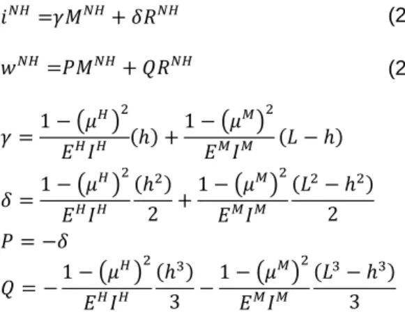
(4) Satoshi Hirose et al / International Journal of Automotive Engineering Vol.12, No.2(2021) 3. Prediction of State Variables via Mathematical Modeling. 𝑖 𝑁𝐻 =𝛾𝑀𝑁𝐻 + 𝛿𝑅𝑁𝐻. (23). 𝑤 𝑁𝐻 =𝑃𝑀𝑁𝐻 + 𝑄𝑅𝑁𝐻. (24). 3.1. Change in Generated Strain with Clearance. 𝐻 2. 𝛾=. When LME cracking is thought to occur from the penetration of molten zinc into the grain boundaries, the mechanical cause of LME cracking is considered to be the tensile stress or strain generated in the tensile direction during the springback. Therefore, using the mathematical model described in the previous section, we predicted the maximum radial stress and maximum strain increment generated in the HAZ region by the springback due to the release of the electrodes when the electrodes were not tilted and when only the clearance was given (Fig. 2). The analytical conditions such as clearance w0 are shown in Table 1. The temperature history parameters and thermal contraction parameters were taken from Ref. (9). When there was no clearance, that is, when w0 = 0, the springback did not naturally occur, and there was no springback-induced stress and strain. When the clearance was increased to w0 = 0.3, the workpiece greatly deformed and high tensile stress and tensile strain increment occurred. It was predicted that when the clearance was increased, the tensile stress would change little and that the tensile strain increment would slightly decrease.. 𝑀 2. 1 − (𝜇 ) 1 − (𝜇 ) (ℎ) + (𝐿 − ℎ) 𝐻 𝐻 𝐸 𝐼 𝐸𝑀 𝐼𝑀 2. 2. 1 − (𝜇 𝐻 ) (ℎ2 ) 1 − (𝜇 𝑀 ) (𝐿2 − ℎ2 ) + 2 2 𝐸𝐻 𝐼𝐻 𝐸𝑀 𝐼𝑀 𝑃 = −𝛿 2 2 1 − (𝜇 𝐻 ) (ℎ3 ) 1 − (𝜇 𝑀 ) (𝐿3 − ℎ3 ) 𝑄=− − 3 3 𝐸𝐻 𝐼𝐻 𝐸 𝑀 𝐼𝑀 𝛿=. Final deflection angle iNH and final deflection wNH at the boundary between the nugget region and the HAZ region on the UL, UR, LL, and LR sides can be obtained by integrating Eqs. (10) and (19), substituting r = 0 into the equations derived from the integration, and by adding the values calculated by the derived equations to those calculated by Eqs. (23) and (24). However, MNH and RNH in Eqs. (23) and (24) are derived by following the geometric constraint conditions (Eqs. (25) to (28)) about deflection angle iNH and deflection wNH at the boundary between the nugget region and the HAZ region and the force balance conditions (Eqs. (29) to (32)). 𝑁𝐻 𝑁𝐻 𝑖𝑈𝑅 + 𝑖𝑈𝐿 =0. (25). 𝑁𝐻 𝑁𝐻 𝑖𝐿𝑅 + 𝑖𝐿𝐿 =0. (26). 𝑁𝐻 𝑁𝐻 𝑤𝑈𝑅 = 𝑤𝐿𝑅 + 𝑡0. (27). 𝑁𝐻 𝑁𝐻 𝑤𝑈𝐿 = 𝑤𝐿𝐿 + 𝑡0. (28). 𝑁𝐻 𝑁𝐻 𝑀𝑈𝑅 = 𝑀𝐿𝑅. (29). 𝑁𝐻 𝑁𝐻 𝑀𝑈𝐿 = 𝑀𝐿𝐿. (30). 𝑁𝐻 𝑁𝐻 𝑅𝑈𝑅 = 𝑅𝐿𝑅. (31). 𝑁𝐻 𝑁𝐻 𝑅𝑈𝐿 = 𝑅𝐿𝐿. (32). Fig. 2 Clearance vs. radial stress / strain increment. From Eqs. (23) and (24), the unknowns are MNH and RNH on the respective sides, or there are a total of eight unknowns. These unknowns can be obtained by a total of eight equations from Eqs. (25) to (32). Here, t0 is the initial clearance between the two steel sheets. In this report, the initial clearance is put to t0 = 0 by assuming that the two steel sheets are in tight contact. In addition, because the deformation is elastic, radial stress increment r and radial strain increment r are obtained by Eqs. (20) and (31) from MNH and RNH on the respective sides. The final stress and strain are obtained by adding the values calculated by Eqs. (15) to (18) in Section 2.2 to those calculated by Eqs. (20) and (21) in this section. The stress and strain increments generated by the springback due to the release of electrodes can be obtained by subtracting the stress and strain obtained from Eqs. (15) to (18) in Section 2.2 from the finally obtained stress and strain.. Fig. 3 Clearance vs. radial strain Table 1 Analytical conditions Geometric condition Evaluated Parameter Clearance w0 Length L HAZ width h Nugget diameter ND Difference from temperature. w0 /mm. i0 /deg. ND /mm. h /mm. L /mm. 0.0~1.0 2.0 1.0 0.5. 0 10 0 0. 5.1 5.1 5.1 3.0~7.0. 1.0 1.5 1.0~3.0 1.5. 40 20~200 40 40. 0.5. 0. 5.1. 1.5. 40. Copyright 2021 Society of Automotive Engineers of Japan, Inc. All rights reserved. Copyright © 2021 Society of Automotive Engineers of Japan, Inc. All rights reserved. 51.
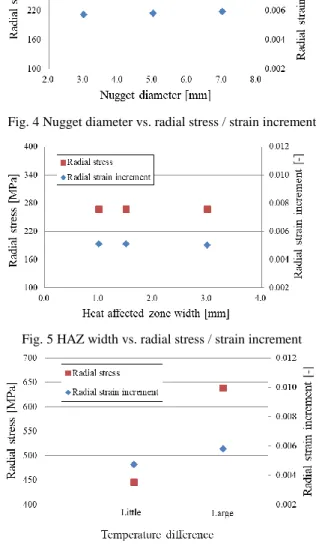
(5) Satoshi Hirose et al / International Journal of Automotive Engineering Vol.12, No.2(2021) This is thought as follows: When the electrode force was applied as described in Section 2.2, the larger the clearance, the wider the plastic deformation that occurred and the less the localization of deformation became in the HAZ region. Next, the total strain after the springback is shown in Fig. 3. It is evident that the larger theclearance, the higher the strain becomes after the springback. This effect could decrease the possibility of LME cracking occurring with increasing clearance. 3.2. Influencing Factors for the Generation of Strain due to Disturbances Next, we predicted the effects of nugget diameter ND, HAZ width, temperature difference, and constraint force (at distance L from the nugget region to point F in Fig. 1) when the application of disturbances was assumed. The studied parameters and their values are shown in Table 1. Following the conditions of Ref. (1), the effect of the temperature difference was compared between the case where the initial temperature difference between the nugget region and the HAZ region was small (temperature difference dt = 800°C) and the case where the initial temperature difference between the nugget region and the HAZ region was large (dt = 1,470°C). The respective results are shown in Figs. 4 to 7.. Fig. 7 Surrounding geometric constraint force vs. radial stress / strain increment Consequently, the effects of nugget diameter ND and HAZ width h on the stress and the strain increment during the springback in the LME-susceptible regions were found to be relatively small. On the other hand, the effects of the temperature difference and the constraint force were relatively large. When the temperature difference was large and when the constraint force was high, the stress and the strain increment generated when electrodes were released were large and were expected to increase the likelihood of LME cracking. 4. Evaluation of the Effect of Clearance on LME Cracking via Welding Testing 4.1. Welding Test Conditions Galvannealed steel sheets with a tensile strength of 980 MPa were used as evaluation materials. Two 1.6 mm thick galvannealed steel sheets were spot welded. The electrode force was set to 400 kgf, and the weld time was set to 17 cycles (converted value at 50 Hz). The hold time after the application of the weld time was measured to be four cycles. The weld current was increased from 5.0 kA in 0.5 kA increments until nugget diameter ND exceeded 7.0 mm. The test under these welding conditions was conducted without tilting the electrodes and by changing the clearance from 0 mm to 1.0 mm so as to evaluate the effect of the clearance on LME cracking.. Fig. 4 Nugget diameter vs. radial stress / strain increment. 4.2. Welding Test Results Figure 8 shows nugget diameter ND and LME crack depth with the respective clearances. From Fig. 8, it cannot be said that the LME cracks occur more frequently as the clearance increases. The effect of the clearance on the LME cracking tendency depends on nugget diameter ND. It was confirmed that LME cracks are likely to occur when the clearance is small.. Fig. 5 HAZ width vs. radial stress / strain increment. Fig. 6 Temperature difference between nugget and HAZ vs. radial stress / strain increment. Fig. 8 Nugget diameter vs. crack depth for each clearance. Copyright 2021 Society of Automotive Engineers of Japan, Inc. All rights reserved. Copyright © 2021 Society of Automotive Engineers of Japan, Inc. All rights reserved. 52.
(6) Satoshi Hirose et al / International Journal of Automotive Engineering Vol.12, No.2(2021) Section 3, the reduction of the temperature difference and the reduction of the geometric constraint force of the steel sheets are considered to reduce the stress and strain around the spot welds after the release of the electrodes and are regarded as effective in preventing LME cracking. 5. Conclusions We felt that the residual stress or strain caused when electrodes separate from steel sheets is the driving force of LME cracking, and we thus built a mathematical model that can consider the effect of springback in the cooling time and the release time. In addition, we estimated the welding-induced residual stress and strain via the mathematical model, conducted welding tests under the same conditions as those of the mathematical model, and obtained the following conclusions: (1) The experimentally determined LME cracking tendency with respect to the clearance agreed well with the stress and strain results predicted by the mathematical model. (2) The mathematical model predicted that the residual stress and strain can be reduced by reducing the temperature difference between the nugget region and the HAZ region and by reducing the constraint force from the surrounding steel sheets.. Fig. 9(a) Cross section photo (current 5.0kA~6.0kA). “This paper is written based on a proceeding presented at JSAE 2020 Annual Cogress (Spring).” References (1) Youhei Suzuki , et al. : Infiniti QX50, EuroCarBody2018 20th global car body benchmarking conference, (2018). (2) Taniguchi Kohichi, et al.: Development of resistance spot welding technology to suppress LME crack in ultra high strength steel sheets (3rd report), Preprints of the National Meeting of JWS (in Japanese), No.100 Page.ROMBUNNO.10, (2017). (3) Du-Youl Choi, et al. : Parameter study for liquid metal embrittlement in resistance spot welds of galvanized trip steel, Sheet metal welding conference XVIII, October17-18, (2018). (4) Kinichi Matsuyama : Simulation techniques resistance spot welding, Quarerly Journal of JWS (in Japanese), Vol.70, No.5, pp.5.96-609, (2001). (5) Muneyoshi Iyota, et al. : Numerical simulation of nugget size and residual stress of resistance spot welded HT980 steel sheet, Quarerly Journal of JWS (in Japanese), Vol.29, No.2, pp.86-95, (2011). (6) Gen Murayama, Hatsuhiko Oikawa : Current status of spot welding simulation technology, Welding technology (in Japanese), SANPO PUBLICATIONS, INC., Vol.59, No.3, pp.70-74, (2011). (7) Takeo Naka, Toshie Okumura : Thermal stress due to welding on the thin steel plate-part I, Journal of JWS (in Japanese), Vol.17, No.3, pp.86-96, (1948). (8) Masaki Watanabe, Kunihiko Sato : Thermal stress and residual stress of circular plate heated at it’s centre, Journal of the society of naval architects (in Japanese), No.86, pp.185197, (1949). (9) Satoshi Hirose : Analytical evaluation of distribution of thermal residual stress by resistance spot welding, Proceedings of the annual meeting of the JSME/MMD (in Japanese), GS18, (2019). (10)Katsumi Kawata, et al. : Bending (approach to high accuracy) (in Japanese), Tokyo, CORONA PUBLISHING CO.,LTD., 260p, (1995).. Fig. 9(b) Cross section photo (current 6.5kA~7.5kA) Cross-sectional photographs of spot welds are shown in Figs. 9(a) and 9(b). The LME cracks are enclosed in red circles. Cracks that seem to be LME cracks can be observed outside the spot welds and near where the steel sheets are separated. Also, it can be confirmed that LME cracks easily occur under the conditions of 0.3 and 0.5 mm clearances. As predicted by the mathematical model in Section 3.1, the stress and strain do not occur as a driving force for LME cracking when there is no clearance. When the clearance is set, high stress and strain occur during springback. The LME cracking tendency is increasingly prevented as clearance increases. These results are considered to agree well with the test results. Like the analysis results of the mathematical model, the test results show that the larger the clearance, the wider the plastic deformation range gets and that the effect of springback due to the release of electrodes is reduced. This mathematical model includes several assumptions for the simplicity of calculation, but its predicted results agree well with the test results. As predicted by the mathematical model in. Copyright 2021 Society of Automotive Engineers of Japan, Inc. All rights reserved. Copyright © 2021 Society of Automotive Engineers of Japan, Inc. All rights reserved. 53.
(7)
図
関連したドキュメント
For instance, we have established sufficient conditions of the extinction and persistence in mean of the disease, as well as the existence of stationary distribution.. However,
By using the averaging theory of the first and second orders, we show that under any small cubic homogeneous perturbation, at most two limit cycles bifurcate from the period annulus
It is suggested by our method that most of the quadratic algebras for all St¨ ackel equivalence classes of 3D second order quantum superintegrable systems on conformally flat
Analysis and numerical results are presented for three model inverse problems: (i) recovery of the nonlinear parameter in the stress-strain relation for a homogeneous elastic rod,
Using meshes defined by the nodal hierarchy, an edge based multigrid hierarchy is developed, which includes inter-grid transfer operators, coarse grid discretizations, and coarse
In this work, we present a new model of thermo-electro-viscoelasticity, we prove the existence and uniqueness of the solution of contact problem with Tresca’s friction law by
“Breuil-M´ezard conjecture and modularity lifting for potentially semistable deformations after
Some new oscillation and nonoscillation criteria are given for linear delay or advanced differential equations with variable coef- ficients and not (necessarily) constant delays
