Kyushu University Institutional Repository
Shallow crack effect in residual tensile
strength evaluation of finite-sized structures made of ductile materials
劉, 何
http://hdl.handle.net/2324/4110414
出版情報:九州大学, 2020, 博士(工学), 課程博士 バージョン:
権利関係:
tensile strength evaluation of finite- sized structures made of ductile
materials
A dissertation submitted to
Graduate School of Engineering, Kyushu University, Japan for the degree of Doctor of Philosophy in Hydrogen Energy System
Presented by
LIU HE
April 2020
i
Index
Abstract ... iii
List of abbreviations ... v
Nomenclature ... vi
CHAPTER 1. General introduction ... 1
1. 1 Research background ... 1
1.1.1 Residual strength of pre-cracked structures ... 1
1.1.2 Physical meanings of residual strength ... 6
1.1.3 Research gap in residual strength of shallow pre-cracked structures ... 10
1. 2 Purpose of this study ... 12
1. 3 Thesis outline ... 14
CHAPTER 2. Equivalence between shallow notch and shallow crack in structural failure caused by plastic instability ... 17
Introduction ... 17
2. 1 Methodology ... 20
2.2.1 Concept of shallow crack-like notch identification ... 20
2.2.2 Implementations of finite element analysis and experimental verification ... 22
2. 2 Results ... 29
2. 3 Discussion ... 36
2. 4 Chapter conclusions ... 39
CHAPTER 3. Shallow crack effect on evaluation of residual tensile strength: harmless and stable cracks in finite-sized structure made of ductile metals ... 41
3. 1 Introduction ... 41
3. 2 Experimental and analytical methods ... 43
3.2.1 Material and testing ... 43
3.2.2 Implementation of finite element analysis ... 46
3. 3 Results ... 49
3. 4 Discussion ... 62
3.4.1 Shallow crack effect in residual strength issue and its general applicability .... 62
3.4.2 Mechanism of shallow crack effect ... 64
3. 5 Chapter conclusions ... 67
CHAPTER 4. Residual strength prediction of shallow cracked structures ... 69
4. 1 Introduction ... 69
4. 2 Qualitative trend prediction of residual strength ... 71
4.2.1 Novel failure assessment diagram and classification of pre-cracks for predicting residual strength variation ... 71
ii
4.2.2 Influential factors on shallow crack effect in residual strength issue ... 74
4. 3 Quantitative prediction of residual strength ... 76
4.3.1 Numerical modeling ... 76
4.3.2 Results and discussion ... 81
4. 4 Chapter conclusions ... 83
CHAPTER 5. Distinguishing geometric and metallurgic hydrogen-embrittlement susceptibilities in pre-cracked structures made of interstitial-free steel under monotonic tension ... 84
5.1 Introduction ... 84
5.2 Experimental Procedure ... 86
5.2.1 Material and specimen ... 86
5.2.2 Hydrogen charging ... 87
5.2.3 Monotonic tensile tests ... 89
5.3 Results ... 89
5.4 Discussion ... 95
5.5 Chapter conclusions ... 99
CHAPTER 6. General conclusions ... 101
Appendix ... 103
A1. Microstructure of IF steel and measurement of grain size... 103
A2. Measurement of notch dimensions ... 104
A3. Stress-strain curves for specimens of continuous tests listed in Table 3.1 ... 106
References ... 107
Acknowledgment ... 121
iii
Abstract
Residual strength, which reflects the practical load-carrying capacity of pre-damaged structures, is a critical concern in fail-safe design. As a representative case of local stress intensifiers, pre- existing cracks (pre-cracks) in engineering structures have attracted the most attention of residual strength investigations. Conventionally, residual strength issues of pre-cracked structures are solved by fracture mechanics with a presumption of the unstable crack propagation dominating the loss of load-carrying capacity. That is, fracture instability characterized by fracture instability toughness is regarded as the physical meaning of residual strength. With the joint efforts of mechanical and material researchers, however, the pre-cracks are becoming mechanically shallower, and the materials are becoming stronger and tougher, resulting in an extremely high fracture instability toughness that makes the unstable crack propagation hardly occur. Hence, as plasticity develops with loading, if plastic instability, such as the necking, instead of fracture instability dominating residual strength of shallow pre-cracked structures, most previous studies probably become invalid.
Moreover, the plastic instability dominating residual strength can challenge the general viewpoint of engineering that cracks weaken structures. First, as an extreme case of the notch that the notch root radius approaches to zero, crack is widely considered to have no strengthening effect, such as notch strengthening, because unstable crack propagation is believed to occur at low stress. However, this situation will be changed if plastic instability can dominate the residual strength of shallow pre- cracked structures because plastic strain localization induced by crack can resist the general yielding and plastic instability. Second, the extremely high fracture toughness of shallow cracks may make the factors that can enhance the plastic strain localization in the pre-cracked cross-section favorable for residual strength, such as the increase of pre-crack depth within a certain range or the change in the plasticity property of the material. These assumptions are necessary to be verified due to the insufficient investigation of residual strength in the presence of shallow pre-cracks.
Based on the above, this dissertation focused on the residual tensile strength of shallow pre- cracked structure made of interstitial-free (IF) steel. In order to guarantee the symmetry of pre-crack
iv
shape, measurability of pre-crack depth and constrained pre-strain in specimen, the shallow crack- like notch was adopted, and the identification criterion of shallow crack-like notches in the case of plastic instability prevailing was proposed initially. Then, the trends, physical meanings, and corresponding damage characteristics of residual strength responding to the pre-crack depth were clarified. Meanwhile, the concept of shallow crack was redefined for residual strength issues, and the mechanism of shallow crack effect on residual strength was explained by analyzing whether the plastic strain localization induced by pre-crack positively or negatively affects the load-carrying abilities in different imaginary partitions of pre-cracked cross-sections. After that, the qualitative and quantitative predictions of the residual strength in the presence of shallow cracks were preliminarily explored. Qualitative prediction focused on the trend analysis of residual strength from the perspective of plastic strain localization, while quantitative prediction focused on the necessary considerations for correctly predicting residual strength values and corresponding damage characteristics. Eventually, the concept of shallow cark effect was applied to the hydrogen environment, in which the magnitude of plastic strain localization can be dramatically raised.
Aforementioned work extent residual strength theory into the field of shallow cracks.
In addition, the redefinition of shallow crack for residual strength issue, a novel failure- assessment diagram, and the subdivision of hydrogen-embrittlement susceptibilities in this study were expected to help identify and analyze the shallow crack effect in practical applications related to residual strength.
v
List of abbreviations
EBSD Electron backscatter diffraction
EPFM Elastic-plastic fracture mechanics
FAD Failure assessment diagram
FEA Finite element analysis
FSY Full-scale yielding
HAC Hydrogen-assisted cracking
HE Hydrogen embrittlement
HEDE Hydrogen-enhanced decohesion
HELP Hydrogen-enhanced localized plasticity
KAM Kernel average misorientation
LEFM Linear elastic fracture mechanics
LSY Large-scale yielding
SEM Scanning electron microscope
SSY Small-scale yielding
MSC Material selection chart
UTS Ultimate tensile strength
vi
Nomenclature
𝐴int Initial area of intact cross-
section 𝛼 Notch opening angle
𝐴net
Initial area of net cross-section reduced by the presence of notch/crack
𝜀𝑒, 𝜀𝑡 Engineering and true strain
𝐸 Young’s modulus 𝜀𝑖𝑗𝑝 Plastic strain tensor
𝑒𝑖𝑗𝑝 Plastic strain deviator tensor 𝜀𝑖𝑖𝑝𝑙: 𝜀𝑥𝑥𝑝𝑙, 𝜀𝑦𝑦𝑝𝑙, 𝜀𝑧𝑧𝑝𝑙
Normal coordinate plastic strains (𝑥, 𝑦-direction) and tangential (𝑧- direction) plastic strain
𝐻 Gage length 𝜀̅𝑖𝑖𝑝𝑙: 𝜀̅𝑥𝑥𝑝𝑙, 𝜀̅𝑦𝑦𝑝𝑙, 𝜀̅𝑧𝑧𝑝𝑙
Uniform (averaged) normal coordinate plastic strains (𝑥, 𝑦- direction) and tangential (𝑧-direction) plastic strain
𝐾t Stress concentration factor 𝜂 Stress triaxiality
𝑘 Yield stress in pure shear 𝜆 Elongation in gage length 𝑙 Ligament size of notch/pre-
cracked cross-section 𝜋 Circumference ratio
𝑃 Applied load 𝜌 Notch root radius
𝑟 Radius of intact cross-section 𝜎Y Yield strength (0.2% offset yield strength)
𝑆 Distance from crack tip along
crack plane 𝜎1, 𝜎2, 𝜎3 Principal stresses, 𝜎1> 𝜎2> 𝜎3 𝑠𝑖𝑗 Stress deviator tensor 𝜎𝑒, 𝜎𝑡 Engineering and true stress
𝑡 Notch/pre-crack depth 𝜎𝑒𝑞 von Mises equivalent stress 𝛥𝑡 Crack depth increment 𝜎ℎ Hydrostatic stress
𝑈𝑥, 𝑈𝑦
Normal coordinate
displacements 𝜎𝑖𝑗 Cauchy stress tensor
𝑣 Poisson’s ratio 𝜎𝑖𝑖: 𝜎𝑥𝑥, 𝜎𝑦𝑦, 𝜎𝑧𝑧
Normal coordinate stresses (𝑥, 𝑦- direction) and tangential (𝑧-direction) stress
𝑌 Yield stress in uniaxial
loading 𝜎R Residual strength based on intact
cross-section
𝛿𝑖𝑗 Kronecker delta 𝜎𝑏, 𝜎𝑏net Tensile strength (or notch tensile strength) based on net cross-section
1/121
CHAPTER 1. General introduction
1. 1 Research background
1.1.1 Residual strength of pre-cracked structures
Residual strength reflects the maximal stress below which a defective structure can still carry without falling [1–4]. That is, it indicates the practical load-carrying capacity in the presence of flaws, which usually deviates from the designed structural strength.
It is a consensus that achieving flawlessness is almost impracticable with present engineering technology.Various product quality deficiencies, such as cracks, punctures, and burrs, and service-induced damages, such as scratches, wear scars, and corrosion pits, widely exist in engineering structures. They are the source of local stress intensifications and are widely believed by engineers and scholars to herald degradations in load-carrying capacity [4–10]. Hence, to prevent unexpected failures, the residual strength evaluation is a crucial concern in fail-safe designs.
As a representative case of local stress intensifiers, pre-existing cracks (pre-cracks) in engineering structures have attracted the most attention of residual strength study [11–13]. The most direct and classical way to evaluate the residual strength of pre- cracked structures is replicating the identical working conditions through experiment.
Naturally, it requires extensive experiments to deal with various cracks when engineers do not have a clear recognition of the underlying reasons for the loss of load-carrying capacity. With the developments of mechanical engineering and material science, many attempts have been made to find widely applicable tools to anticipate failures in advance. Especially the modern fracture mechanics, which was unveiled by Griffith
2/121
energy balance model proposed in 1920 [14] and matured by proposing concepts of stress intensity factor (usually written as 𝐾) for linear elastic fracture mechanics (LEFM) in 1957 [15] and 𝐽 contour integral (usually written as 𝐽) for elastic-plastic fracture mechanics (EPFM) in 1968 [16], had significantly prompted the residual strength analysis of pre-cracked structures by correlating the allowable stress and crack depth with the fracture toughness [17–20]. The residual strength of pre-cracked structures can be derived based on the fracture mechanics approach [21,22], such as the failure assessment diagrams (FAD) shown in Fig. 1.1, the material selection charts (MSC) shown in Fig. 1.2, and a straightforward failure strength vs. crack depth relation in Fig.
1.3.
Fig. 1.1 Failure assessment diagram (FAD) covering fully brittle to fully ductile behavior [17,22,23].
3/121
Fig. 1.2 Correlation map of fracture toughness vs. strength used in selecting material for damage- tolerant design [20].
Fig. 1.3 Schematic of relationship between failure strength and crack depth (stable crack propagation includes non-propagating crack) [1,24].
4/121
Although fracture mechanics has been a primary means for residual strength issues, the theory of residual strength evaluation and prediction is still immature. The cracking behavior is the critical concern of fracture mechanics, while the onset of unstable crack propagation may not occur even applied stress approaching the allowable stress determined by the plastic flow property [25], such as the cut-off lines for fracture mechanics approach in Figs. 1.1 and 1.3. Beyond the scope of fracture mechanics, investigations are insufficient, so the evaluation of residual strength still mainly relies on the experiment and experience. Moreover, when fracture happens after the general yielding, the mixed-use of yield strength and ultimate strength to define the failure strength [24,26] in the fracture mechanics approach makes the determination of residual strength unclear. This further highlights that the research on residual strength should not be limited by fracture mechanics. The above problems of the present residual strength study are just the tips of the iceberg. Existing theories can be used to improve the research on residual strength, but they should not be the constraints. A new framework must be proposed for future investigations of residual strength.
In this study, residual strength is suggested to be identical to the ultimate structural strength regardless of the general yielding. The yield strength is critical for mechanical design because it guarantees the normal operation of machines. However, the onset of general yielding due to unreasonable loading can be avoided through sophisticated design. Meanwhile, as the concept of user-friendly becoming increasingly important in modern society, the idea of fail-safe design is changing from prioritizing the machine integrity to prioritizing personnel safety in emergencies, such as introducing crumple zones in automobile design [27]. The higher ultimate tensile or compressive strength can absorb more energy before losing the load-carrying capacity to protect the operator.
Extensive vehicle crash tests, as shown in Fig. 1.4, have proven that a proper plastic
5/121
deformation can save lives in accidents [28]. In summary, the yield strength is for machine operation, and the residual strength is for personnel safety.
Fig. 1.4 (a) Vehicle crash test (Nissan Juke, DIG-T 117, N-Connecta, LHD [29]); (b) Cars with crumple zones help save lives in accidents through plastic deformation [28].
6/121
1.1.2 Physical meanings of residual strength
A variety of reasons can cause the loss of load-carrying capacity, that is, the physical meaning of residual strength various with practical working conditions. The physical meanings of residual strength can be summarized as fracture instability, plastic instability, and geometric instability [18]. Different physical meanings may compete with each other to dominate the residual strength in applications. Hence, understanding these physical meanings is a prerequisite for the in-depth study of residual strength.
1.1.2.1 Fracture instability
The onset of unstable crack propagation can limit the residual strength, whose critical condition is called ‘fracture instability’ [30]. It is the general consideration of residual strength evaluation according to the fracture mechanics approach. The crack propagation may become immediately unstable after brittle fracture initiation, or it may occur after a stable ductile tearing [17]. Hence, this critical condition can be determined by fracture initiation toughness of brittle fracture, or fracture instability toughness on a rising crack-extension resistance curve (𝑅-curve) of ductile fracture [30,31]. When the driving force of crack propagation is always higher than the fracture toughness, the unstable crack propagation begins. For instance, as shown in Fig. 1.5, if the driving force of a crack is characteristic by energy release rate [32], G, and 𝑅 denotes the resistance, then the condition for stable crack propagation is
G= 𝑅 (1-1)
for the case of brittle fracture shown in Fig. 1.5 (a), or
𝑑G 𝑑𝑎≤ 𝑑𝑅
𝑑𝑎 (1-2)
7/121
for the case of ductile fracture shown in Fig. 1.5 (b). Correspondingly, the unstable crack propagation occurs when
𝑑G 𝑑𝑎> 𝑑𝑅
𝑑𝑎 (1-3)
Therefore, the crack is non-propagating at 𝜎1 for both Figs. 1.5(a) and (b). As the applied stress increases, fracture initiates at 𝜎2, and this critical condition is called fracture initiation toughness. For brittle fracture shown in Fig. 1.5 (a), the fracture instability toughness coincides with fracture initiation toughness because the resistance is a fixed value. However, the ductile fracture will remain stable until applied stress increases to 𝜎4, that is, approaching fracture instability toughness. Although the fracture toughness for unstable crack propagation should be called fracture instability toughness, it is commonly referred to fracture initiation toughness in the case of Fig.
1.5 (a) and fracture instability toughness in the case of Fig. 1.5 (b) in fracture mechanics study to distinguish brittle and ductile fractures. However, in this study, the onset condition for unstable crack propagation will becollectively called fracture instability toughness to highlight the physical meaning of residual strength, namely, fracture instability.
Fig. 1.5 Schematic driving force, G, vs. R-curve diagrams (𝑎0 is pre-crack depth, 𝑎𝑐 is critical crack depth at fracture instability and 𝜎 with subscript is applied stress, 𝜎1 > 𝜎2 > 𝜎3 > 𝜎4) [17]:
(a) flat R-curve for brittle fracture and (b) rising R-curve for ductile fracture.
8/121
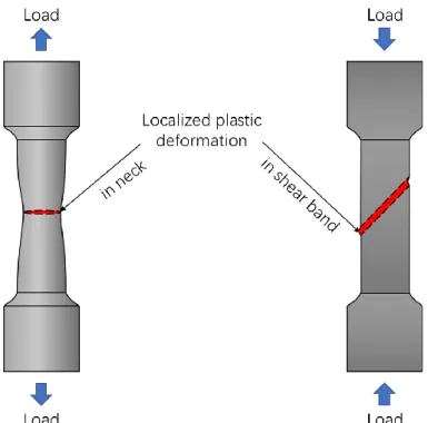
1.1.2.2 Plastic instability
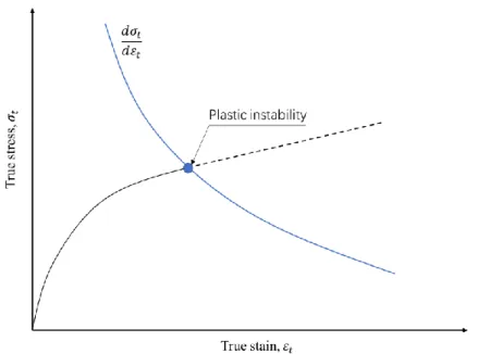
The plastic instability [33–37] generated by the insufficient strain hardening offsetting the stress increment [38]. Typical physical phenomena, for instance, are known as necking and shear banding, as shown in Fig. 1.7. A classical mathematical solution for the onset of plastic instability by Considère [39]focuses on the critical condition of the true stress, 𝜎𝑡, vs. true strain, 𝜀𝑡, (or load vs. elongation) curve reaching a maximum value, as shown in Fig. 1.8. That is,
𝑑𝜎𝑡
𝑑𝜀𝑡 = 𝜎𝑡 (1-4)
This condition is special for very ductile pre-cracked structures, or pre-cracks are very shallow, so their fracture instability toughness may increase to an extremely high value with lowing plastic constraint [40]. Hence, the residual strength of pre-cracked structures also can be dominated by plastic instability.
Fig. 1.7 Schematic necking and shear banding induced by plastic instability.
9/121
Fig. 1.8 Onset of plastic instability in true stress, 𝜎𝑡, vs. true strain, 𝜀𝑡, curves.
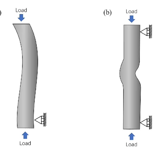
1.1.2.3 Geometric instability
Geometric instability limits the load-carrying capacity as a result of the dramatic geometric deflection deviating the deformation path from the original loading path. The typical physical phenomena are buckling and bulging [41–43], as shown in Fig, 1.9.
Geometric instability is usually prohibited in the initial design, and it also rarely appears before the onset of fracture instability or plastic instability in pre-cracked structures.
Hence, it is not a major consideration of this study. However, it should note that sometimes people confuse geometric instability with plastic instability because a considerable deflection may become plastic, and a dramatic geometric deflection also may happen after the onset of plastic instability. Here, we emphasize that the plasticity in geometric instability, if it has, is induced by geometric deflection with a significant variation in the loading path, while the plastic instability depends on the plastic flow property without a significant variation in the loading path. That is, geometric
10/121
deflection is the fundamental reason for geometric instability, and localized plastic deformation is responsible for plastic instability.
Fig. 1.9 Geometric instability due to large geometric deflection that deviates deformation path from original loading path: (a) buckling and (b) bulging.
1.1.3 Research gap in residual strength of shallow pre-cracked structures
With the assistance of fracture mechanics, general considerations of residual strength mainly focus on cracks deeply embedded in structures [2,3,7–12,44]. However, as technology advances, most pre-cracks in engineering structures nowadays become very shallow. Such shallow cracks [40] (mechanically shallow cracks), whose plastic zone
11/121
size is usually comparable to the crack depth or even structure dimensions [45,46], have been recognized to have distinct mechanical properties [47,48] and may result in anti- commonsense phenomena, such as the shallow (or short) crack problem in fatigue [49].
Nevertheless, previous studies have rarely involved the residual strength issue of shallow pre-cracked structures, neither the physical meaning of residual strength nor the corresponding damage characteristic has been clarified, let alone reasonable evaluations and predictions.
Experiences of addressing the residual strength of deep pre-cracked structures based on fracture mechanics [1,50] are occasionally invalid for shallow pre-cracked structures.
Most previous studies [2,3,7–12,44], typically presupposing a small-scale yielding (SSY) [51–53] condition, implied the physical meaning of residual strength is fracture instability [10,12]. Hence, the residual strength is determined by fracture initiation toughness of brittle fracture or fracture instability toughness on a rising crack extension resistance curve (R-curve) of ductile fracture [30,31]. Both the former and latter are regarded as material intrinsic properties for deep pre-cracked structures, so the residual strength generally has a definite inverse relationship with the pre-crack depth. However, for shallow pre-cracked structures made of ductile metals, the stress triaxiality [54–56]
is insufficient to confine plasticity, the R-curve thus becomes geometric dependent [17,30,57]. For instance, the shallower the crack, the steeper R-curve and the higher fracture instability toughness [17,30,31,58–61]. Furthermore, when shallow pre-crack in full-scale yielding (FSY) [47] (namely, the general yielding condition) owns a terrifically high fracture instability toughness, the plastic instability may compete with fracture instability to govern the residual strength. The above situations obscure the trends of residual strength with shallow pre-crack depth and doubt the applicability of fracture mechanics.
12/121
With further hypotheses, the notch strengthening phenomenon also impugns the commonsense of cracks weakening the structure because the crack is a particular case of the notch owning a minuscular root radius [17,62]. Even an atomically sharp crack can be blunted immediately with plasticity. Hence, a notch can be equivalent to a crack if its depth is the only influential factor of mechanical properties [63–65]. In turn, the crack may play a similar role as the notch in affecting the structural strength.
Particularly notches with a moderate stress triaxiality can delay the yielding in notched cross-sections before stimulating the local failure (fracture) the notch roots, thereby resulting in notch strengthening phenomenon [54,66–68]. Identically, if the plastic instability, instead of fracture instability, dominates the residual strength, the commonsense of cracks weakening structures would be challenged. However, this assumption still requires laboratory verification because: 1. Notches are design parameters, so the notch strengthening generally is evaluated on net cross-sections rather than the intact cross-sections (gross area of cross-section without considering the presence of pre-crack) of residual strength evaluation; 2. Most conventional failure assessments are subject to yield strength [10,17] to avoid mechanical failure, so they are ineffective for residual strength of shallow pre-cracked structures that consider an extreme case of safety. Therefore, it is necessary to get rid of commonsense in engineering to investigate the ‘shallow crack effect on residual strength evaluation.’
1. 2 Purpose of this study
This study was motivated by the need for a better understanding of the trends, physical meanings, and corresponding damage characteristics of residual strength of shallow pre-cracked structures. With the joint efforts of mechanical and material
13/121
researchers, the pre-cracks are becoming mechanically shallower, and the materials are becoming stronger and tougher. Therefore, this study is considered prospective and necessary for the future fail-safe design.
The residual tensile strength (hereinafter shortened as ‘residual strength’) under plane strain loading was selected as the research object. Because both opening-mode (Mode-I) loading and the plane strain loading are relatively dangerous than other loading configurations in most cases [17]. Since the extensive plasticity was expected to obtain mechanically shallow cracks, interstitial-free (IF) steel (low strength grade with excellent ductility [69], as shown in Fig. 1.10) was used for machining specimens.
Meanwhile, IF steel only consists of a single ferrite phase without a large number of interstitial atoms [70]. It thus supplied a fundamental representation of the mechanical properties of ductile ferrite steels. The entire research architecture was designed to get rid of the shackles of previous studies, so some original definitions and concepts were proposed in the following content. All novel definitions and concepts were inspired by deficiencies in present literature for residual strength study, verified by experimental and numerical results, and generalized by scientific discussion. In summary, this study sought to find answers to the following questions:
1. How to introduce shallow crack on laboratory specimens for the residual strength study?
2. What is the definition of shallow cracks in residual strength issues?
3. What are the shallow crack effects on the trends, physical meaning, and corresponding damage characteristics of residual strength?
4. How to predict the residual strength affected by shallow cracks?
5. What are the potential applications of this research?
14/121
Fig. 1.10 Interstitial-free (IF) steel in steel strength vs. ductility diagram [69].
In this thesis:
Question 1 will be answered in CHAPTER 2.
Questions 2 and 3 will be answered in CHAPTER 3.
Question 4 will be answered in CHAPTER 4.
Question 5 will be partially answered in CHAPTER 5.
1. 3 Thesis outline
This thesis consists of 6 chapters. All chapters are arranged to serve the central theme of ‘shallow crack effect on residual tensile strength evaluation’. The thesis outline is as follows:
Chapter 1 described the general introduction of this study. The development and present level of residual strength study were briefly reviewed to propose a clear and unified definition of residual strength for this study. After indicating the potential
15/121
physical meanings of residual strength, the research gap in residual strength of shallow pre-cracked structures was pointed out. Then, the motivation of this study, namely, improving the residual strength theory in the case of shallow cracks, was formed. The main objectives and originalities of each part of this study were described.
Chapter 2 solved the prerequisite for investigating the residual strength of shallow
pre-cracked structures, that is, the identification of shallow crack-like notches for structural failure. Introducing crack-like notches is essential for this study because fatigue pre-cracking fails to ensure geometric symmetry, pre-crack measurability, and restricted pre-strain of shallow pre-cracked structures under plane strain condition.
However, the results obtained by previous studies related to crack-like notches under small-scale yielding are invalid for shallow notches with extensive plasticity, particularly when plastic instability instead of fracture instability governs the residual strength. From the perspective of asymptotic and phenomenological analysis, this chapter proposed a novel criterion for shallow crack-like notch identification.
Chapter 3 clarified the trends, physical meaning, and corresponding damage
characteristics of residual strength with shallow pre-crack depth. Results showed that the residual strength of shallow pre-cracked specimens was preferentially governed by plastic instability instead of fracture instability. Furthermore, when shallow pre-crack depths were shorter than a critical value, the rupture occurred in the intact cross-section and the residual strength was identical to the tensile strength of smooth specimens. Such an anti-commonsense phenomenon was explained from the perspective of plastic strain localization. Finally, the ‘shallow crack effect’ special for residual strength issues was defined.
16/121
Chapter 4 focused on predicting the residual strength of shallow pre-cracked
structures. The prediction was divided into a qualitative part and a quantitative part. A novel failure assessment diagram correlating to physical meanings of residual strength and damage characteristics was suggested for qualitative predicting the trends of residual strength from the perspective of plastic strain localization. Meanwhile, a new classification of pre-cracks was proposed according to the physical meaning and corresponding damage characteristics of residual strength. The quantitative prediction was expected to be numerical and phenomenological because engineers can easily find out when the prediction method fails. It was implemented by finite element analysis based on continuum mechanics. Then, we evaluated whether the local plastic flow property influenced by pre-cracks could influence the prediction results.
Chapter 5 considered an application of shallow crack effect to a typical case of plastic strain localization enhanced by the hydrogen. Hydrogen embrittlement (HE) is widely believed to be harmful to engineering structures made of ferritic steel, particularly in the presence of pre-cracks. This chapter proved the effectiveness of the shallow crack effect when the characteristic of plastic strain localization is changed.
Additionally, this effect calls into question the general applicability of conventional investigation of HE susceptibility that mainly focuses on the variation of fracture characteristic, which is often defaulted to cause changes in mechanical properties.
Hence, HE susceptibility is deduced to geometric HE susceptibility for shallow pre- cracked structures, while that for deep pre-cracked structures is metallurgic HE susceptibility.
Chapter 6 summarized the results and proposed the outlook.
17/121
CHAPTER 2. Equivalence between shallow notch and shallow crack in structural
failure caused by plastic instability
Introduction
Artificial pre-cracks with various depths are suitable for the laboratory investigation of crack effects on mechanical properties. The familiar method of preparing pre- cracked specimens is fatigue cracking. However, this method may occasionally fail to ensure rigorous investigation conditions, such as the geometric symmetry, pre-crack measurability, and restricted pre-strain. An alternative method is introducing a crack- like notch to resemble a crack [64,71]. Hence, discussions on when a notch is equivalent to a crack have been presented in an extensive body of literature [72–77]. Most of these studies endeavored to achieve a unified criterion for reasonably and conveniently identifying crack-like notches in applications. The core idea of crack-like notch identification has been developed from the empirical correlation between the geometric configuration and damage initiation behavior [72] to the physical reasoning of a situation wherein the plasticity development dominating the fracture process is insensitive to geometric variation [62]. Conventional viewpoint with regard to crack- like notches in a finite-sized structure can be summarized as follows: (1) the plastic zone in front of the notch, which contains the fracture process zone, must not be too large (SSY) to ensure that the free surface has minor influence on the fracture process;
18/121
(2) the plastic zone size must be sufficiently larger than the notch root radius such that the disturbance of the notch root variation to the development of plasticity can be ignored; (3) the mechanical fields controlling the plastic zone in the notched structure must have a broad asymptotic convergence to that of a crack under the same boundary conditions. This criterion, for instance, contributes to correlating the crack and notch problems in laboratory studies [78] and obtaining geometric-independent fracture toughness [79] by the notches.
Nonetheless, regarding the investigation of the structural strength in the presence of artificial pre-cracks, the abovementioned criterion for crack-like notches sometimes may be invalid. The structural strength of a pre-cracked structure can be dominated not only by fracture instability [30], but also by plastic instability [25]. The latter readily occurs in a shallow pre-cracked structure made of a ductile material [38] owing to the low plastic constraint [17], and may have great importance for laboratory investigations and the future advanced design because, nowadays, most preexisting defects in engineering structures become minuscule with the development of processing and material technologies. Classical concepts of crack-like notches require the precondition of small-scale yielding and assume that the fracture progressing at the crack tip is always responsible for failure. Naturally, they cannot satisfy the case of plastic instability prevailing in shallow pre-cracked structures. Amongst small defects, shallow pre-crack is still a representative stress and strain concentrator. Therefore, it is necessary to extend the concept of crack-like notches to the investigations of shallow pre-cracked structures.
This study partially solved the issue of shallow crack-like notches subjected to monotonic tension by only focusing on the plastic instability occurring under plane
19/121
strain conditions without the assistance of pre-crack propagation. Based on finite element analysis (FEA), the boundary condition, geometric configuration, and elastoplastic fields dominating the overall work hardening in notched and pre-cracked cross-sections were considered. This paper proposes that if the structural strength and failure mode are independent of the notch geometry (except for the notch depth), and elastoplastic fields in notched and cracked cross-sections are broadly convergent by asymptotic analysis, then, a shallow notch is equivalent to a shallow crack. The underlying reason is that different elastoplastic field gradients close to the notch root or crack tip may still result in the same overall work hardening in notched and pre-cracked cross-sections. This concept was verified on interstitial-free (IF) steel, which is a typical strain hardening ferrite steel with excellent ductility and simple metallurgical microstructure [70,80]. Additionally, the generality of the identification method and the significance of the influential factors for shallow crack-like notches was discussed in this study.
It should be noted that the definition of tensile strength was based on the net cross- sectional stress because this definition usually is standard for notched specimens. After proving that notches are equivalent to cracks in a certain condition, the tensile strength can be easily transformed to residual strength, which is based on the intact cross-section.
20/121
2. 1 Methodology
2.2.1 Concept of shallow crack-like notch identification
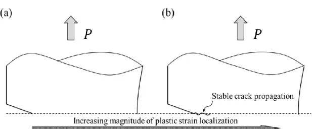
When a pre-cracked specimen is subjected to monotonic tension, plastic instability typically occurs in the form of necking without (Problem I) or with (Problem II) the assistance of stable crack propagation, as shown in Fig. 2.1. Because shallow cracks with an extremely low plastic constraint condition can result in extremely high fracture toughness [30], they will probably not propagate until plastic instability occurs.
Additionally, if a notch imitates Problem II with stable crack propagation in front of the notch root, the notch and stable crack would be equivalent to a crack with the sum of their total depth. Hence, this study focused on Problem I, and Problem II will be discussed in future works.
Fig. 2.1 Tensile static strength of shallow pre-cracked structures dominated by plastic instability (necking) occurring: (a) without crack propagation, and (b) with stable crack propagation.
Both a notch and a crack can cause a gradient distribution in elastoplastic fields.
Hence, it can be easily perceived that if the elastoplastic fields in notched and pre- cracked cross-sections are entirely the same, then, plastic instability will occur under the same condition. However, this is impossible because the severity of stress
21/121
concentration varies with the geometric configurations, and notches and cracks will undoubtedly result in different gradients in elastoplastic fields, particularly close to the notch root and crack tip. In fact, plastic instability fundamentally depends on the overall work hardening in one cross-section, which may still be the same level even if the elastoplastic field have a slight difference in gradients between the notched and pre- cracked structures. First, if a shallow notched structure has a sufficient broad ligament, which makes the disturbance of the notch geometric variation insignificant, the remote elastoplastic fields of the notch root may be convergent to that of the crack tip over a wide range. Second, for most nonlinear power hardening materials, their strain hardening rate decreases as the increase of plastic deformation [54]. Hence, in practice, the increment of the local strain hardening varying with the different elastoplastic field gradients may result in the same load-carrying ability. Basing on this assumption, two requirements for crack-like notches can be derived: 1. The elastoplastic fields in a notched and a pre-cracked cross-section should be broadly convergent to each other such that the influence of the geometric configuration is insignificant. 2. The comparison of elastoplastic field convergence should be made under the same boundary conditions, one of which is at the same structural strength (or load-carrying capacity).
These two requirements can ensure the similarity of the overall work hardening in the notched and pre-crack cross-sections, and they were verified initially by using FEA, and then experimentally verified using specimens made of IF steel.
It should be noted that the “broadly convergent” in the aforementioned first requirement means that the elastoplastic fields, which govern the overall work hardening condition of notched and pre-cracked cross-sections, should coincide with each other in a wide range of ligaments, and the differences of elastoplastic field gradients are only allowed in the vicinity of notch root or crack tip. Although the same
22/121
onset condition of plastic instability only requires the same overall work hardening condition in the yield cross-sections, “broadly convergent” is necessary because it not only limits the crack-like notch geometry but also indicates that identifying crack-like notches should be conducted with the unified structure size and preexisting defect configuration. For instance, comparing the similarity between a shallow notch located in the edge of small structures and a shallow crack embedded in large infrastructures is not recommended at present due to their different constraint state.
2.2.2 Implementations of finite element analysis and experimental verification
In this study, FEA was implemented using ANSYS Workbench (2019 R3) with the large deflection option [81] to compare the elastoplastic fields and critical condition for plastic instability. Because it was expected that the structural strength is independent of geometric configurations, the comparisons of elastoplastic fields were conducted under the maximum load. The base material model came from IF steel, whose grain size and hardness were respectively adjusted to 51.2 μm and 65 HV, respectively, by annealing at 750 °C for two hours and then cooling in air. For detailed information on initial microstructure observation and average grain size measurement, see Appendix A1. The chemical composition of IF steel is presented in Table 2.1.
Table 2.1 Chemical composition of Interstitial-free steel.
Element C N Si Mn P S Ti Al O Fe
Amount (wt. %)
0.0019 0.0008 0.009 ≤ 0.003
≤ 0.002
≤ 0.003
0.029 0.028 0.0015 Bal.
23/121
The material modeling in this study was based on the conventional 𝐽2 flow theory of plasticity [82], which consists of the von Mises yield criterion, associated flow rule, and nonlinear isotropic hardening law. Let 𝜎𝑖𝑗 be the Cauchy stress tensor and 𝜎1, 𝜎2, and 𝜎3 be three principal stress. The hydrostatic stress can be written as
𝜎ℎ = 1
3𝐼1 =1
3𝜎𝑖𝑖 =1
3(𝜎1+ 𝜎2+ 𝜎3) (2-1)
where 𝐼1 is the first invariant of the stress tensor, and the repeated indices (𝑖𝑖) denote the Einstein summation convention. Let 𝑠𝑖𝑗 denotes the stress deviator tensor and its principal values be 𝑠1, 𝑠2, and 𝑠3. The relation between 𝜎𝑖𝑗 and 𝑠𝑖𝑗 is
𝑠𝑖𝑗 = 𝜎𝑖𝑗 − 𝜎ℎ𝛿𝑖𝑗 (2-2)
where 𝛿𝑖𝑗 denotes the Kronecker delta. Then, the second invariant of the deviatoric stress tensor, 𝐽2, is written as
𝐽2 =1
2𝑠𝑖𝑗𝑠𝑗𝑖 = −(𝑠1𝑠2+ 𝑠2𝑠3+ 𝑠3𝑠1) =1
6[(𝜎1− 𝜎2)2+ (𝜎2 − 𝜎3)2+ (𝜎3 − 𝜎1)2 −
2(𝜎1 + 𝜎2+ 𝜎3)2] (2-3)
The von Mises yield criterion presumes that the yielding begins when 𝐽2 reaches a critical value and the yield criterion is written as
𝑓(𝐽2) = 𝐽2− 𝑘2 = 0 (2-4)
where 𝑓 is the yield function, and 𝑘 is the yield stress in pure shear, whose magnitude is √3 times lower than the yield stress under uniaxial loading, 𝑌. Alternatively, Eq. (2- 4) can be transformed into
𝑓(𝐽2) = √3𝐽2− 𝑌 = 𝜎𝑒𝑞− 𝑌 = 0 (2-5)
in which √3𝐽2 is defined as the equivalent stress, 𝜎eq, that is
24/121
𝜎eq = √3𝐽2 = √3
2𝑠𝑖𝑗𝑠𝑗𝑖 = √(𝜎1−𝜎2)2+(𝜎2−𝜎3)2+(𝜎3−𝜎1)2
2 (2-6)
Corresponding to the definition of 𝜎𝑖𝑗, let 𝜀𝑖𝑗𝑝 be plastic strain tensor obtained by subtracting the elastic part from the total strain tensor and 𝑒𝑖𝑗𝑝 be the plastic strain deviator tensor, the equivalent plastic strain, 𝜀eq𝑝 dual to 𝜎eq is written as
𝜀𝑒𝑞𝑝 = √2
3𝑒𝑖𝑗𝑝𝑒𝑗𝑖𝑝 = √2[(𝜀1
𝑝−𝜀2𝑝)2+(𝜀2𝑝−𝜀𝑝3)2+(𝜀3𝑝−𝜀1𝑝)2]
9 (2-7)
When material deforms isotropically, the plastic strain increment is normal to the yield surface, and the flow potential function is identical to 𝑓. Then, the associated flow rule is written as
𝑑𝜀𝑖𝑗𝑝 = 𝑑𝜆𝜕𝑓(𝐽2)
𝜕𝜎𝑖𝑗 (2-8)
where 𝑑𝜀𝑖𝑗𝑝 is the plastic strain increment and its magnitude is denoted as 𝑑𝜆, which is identical to the equivalent plastic strain increment, 𝑑𝜀eq𝑝 , by solving Eq. (2-8).
Consider a nonlinear isotropic hardening condition, 𝑌 will depend on the history of 𝑑𝜀eq𝑝 , that is
𝑌 = Φ(∫ 𝑑𝜀eq𝑝 ) = Φ(𝜀eq𝑝 ) (2-9)
In uniaxial tension, the instantaneous value of 𝑌 and 𝜀eq𝑝 are identical to true stress, 𝜎𝑡, and true plastic strain, 𝜀𝑡𝑝, respectively. 𝜀𝑡𝑝 can be extracted by subtracting the elastic part, 𝜀𝑡𝑒, from the true strain, 𝜀𝑡
𝜀𝑡𝑝 = 𝜀𝑡− 𝜀𝑡𝑒 = 𝜀𝑡−𝜎𝑡
𝐸 (2-10)
25/121
Therefore, the function Φ can be determined from the constitutive relationship of 𝜎𝑡 vs.
𝜀𝑡 obtained by experiment, which is described by Hollomon’s equation [80] in this study, as follows:
𝜎𝑡 = 𝐾𝜀𝑡𝑛 (2-11)
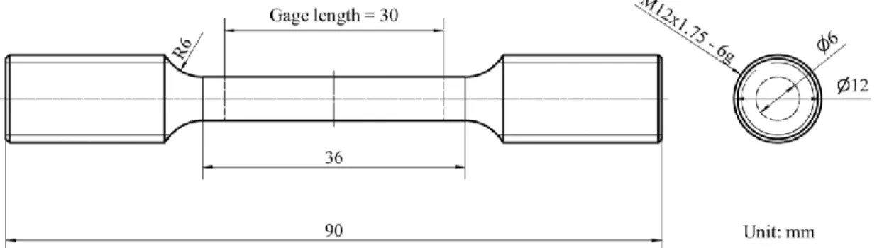
where 𝜎𝑡 is the true stress, 𝜀𝑡 is the true strain, 𝐾 is the strength coefficient, and 𝑛 is the strain-hardening exponent. The variables listed in Table 2.2 were obtained by stretching the smooth round bars made of IF steel according to the ASTM E8M standard [83]. Fig.
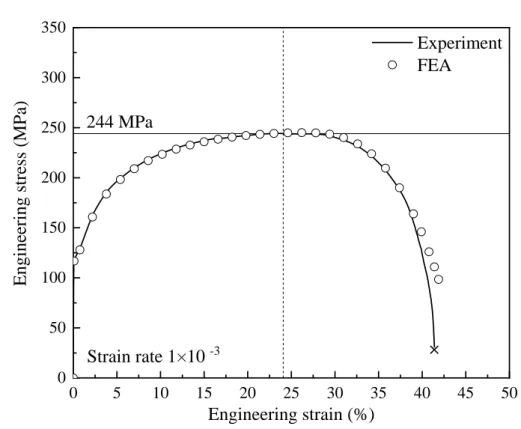
2.2 shows the design of smooth specimen, which is stretched on a precision universal tester (Shimadzu AG-5000A) with an extensometer (Shimadzu SG 50-50). The engineering stress-strain curve of the smooth specimen obtained by FEA agrees well to that obtained by experiment except the final part of post-necking elongation, as shown in Fig. 2.3. The difference the final part of post-necking elongation is probably due to the crack initiation and propagation that accelerate the decrease of load-carrying capacity. However, it has no fluence on determine structural failure by plastic instability.
Table 2.2 Mechanical property of Interstitial-free steel.
Young’s Modulus 𝐸 (GPa)
Poisson’s ratio
𝑣
Yield strength σ𝑌 (MPa)
Tensile strength σ𝑏 (MPa)
Strength coefficient
𝐾 (MPa)
Strain-hardening exponent
𝑛
200.00 0.30 116.1 244.0 456.5 0.27
Fig. 2.2 Design of smooth specimen according to ASTM E8M: Small-size specimen with gage length five times gage diameter.
26/121
Fig. 2.3 Experimental and numerical results of engineering stress-strain curves of smooth specimen.
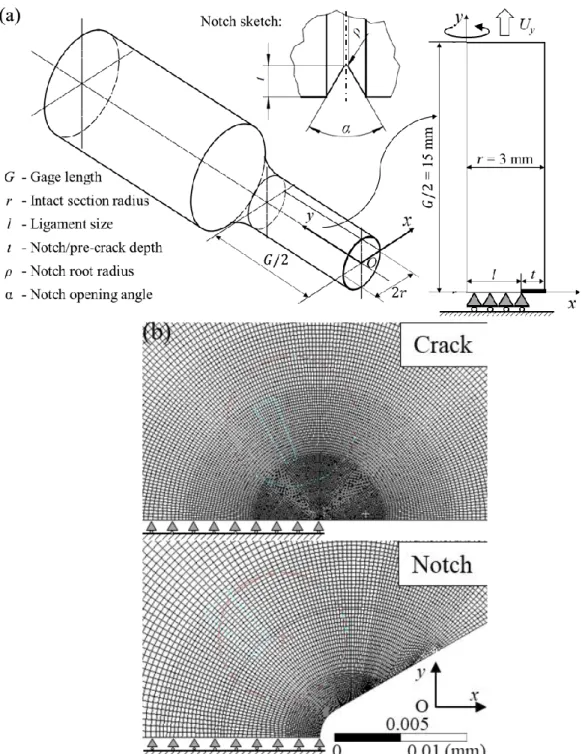
The round bar was simplified to an axisymmetric model, which is a quarter of the gage projected into a 2D Cartesian plane, as shown in Fig. 2.4(a). The circumferential notch and pre-crack were assumed to be introduced in the middle of the gage. The effects of three typical dimensions were considered, namely, the notch root radius, 𝜌, notch opening angle, 𝛼 , and normalized notch or crack depth 𝑡/𝑙. The former two factors are classical considerations (with SSY pre-condition) in crack-like notch discussions because if they do not affect structural failure, the notch depth will be the one and only influential factor, just like the crack depth. The y-axial displacement, 𝑈y, of the notched or pre-cracked cross-section was fixed at 0. The value of the external load, 𝑃, was calculated by the force reaction to 𝑈y at the top edge of the FEA model.
Quadratic (PLANE183 [81]with axisymmetric option) dominant meshing was carried out with the refinements close to the notch root and crack tip, as shown in Fig. 2.4(b).
The minimum element size decreased to 1 μm, which ensured that all flowing results
0 5 10 15 20 25 30 35 40 45 50
0 50 100 150 200 250 300 350
Engineering stress (MPa)
Engineering strain (%)
Experiment FEA
× 244 MPa
Strain rate 1×10 -3
27/121
were independent of element size with a precision of two after the significant digits.
Fig. 2.4 Axisymmetric model for FEA: (a) Simplification, dimensions, and boundary conditions.
(b) Meshing examples for crack and notch.
The distribution of 𝜎eq and 𝜀eq𝑝 in notched and pre-cracked cross-sections were calculated using FEA to evaluate the elastoplastic field convergence. According to Fig.
2.4(a), the principal axes of 𝜎𝑖𝑖 and 𝜀𝑖𝑖𝑝 in the ligament were along the y-axis, the x-axis
28/121
and the circumferential direction of the axisymmetric model, respectively. The local strain hardening property can alter with the elastoplastic field gradients [54]. Hence, in this study, the gross amount of the work hardening condition in one cross-section was quantitively evaluated by averaging the integration of the local strain hardening modulus, as follows:
𝐻̅ =∫ 𝐻𝑑𝑙
𝑙 0
𝑙 (2-12)
where l is the ligament size; 𝐻 is the local strain hardening modulus approximating the trend of the load-carrying ability varying with the strain increment, as follows:
𝐻 = 1
𝑁∑ 𝜎eq(𝑖+1)−𝜎eq(𝑖)
𝜀eq(𝑖+1)𝑝 −𝜀eq(𝑖)𝑝
𝑁𝑖=1 (2-13)
where 𝑁 is the number of loading steps in the plastic range, and the initial value of 𝜎eq(𝑖) is determined at 𝜀eq(0.2)𝑝 = 0.2%. The minimum value of 𝑁 in this study is 500 steps to guarantee a precision of two after the significant digits for 𝐻̅. Therefore, for a crack-like notch, the distributions of 𝜎eq and 𝜀eq𝑝 , and the value of 𝐻̅ in the notched cross-section should be similar to those in the pre-cracked cross-section.
After identifying the crack-like notch by FEA, the experimental verification was carried using the notched specimens. The specimen dimensions were the same as those in the test for obtaining the base material model, as shown in Fig. 2.3. The notches were introduced in the longitudinal middle of the gage part and their dimensions are listed in Table. 2.3. For detailed information on the measurement of the notch dimensions, see Appendix A2. The tensile strength, 𝜎𝑏, of the notched specimens is defined as the ratio of the maximum load, Pmax, to the initial net cross-sectional area, 𝐴0net. Microstructural observations were performed on a SEM at 15 kV to determine the damage as a response to the geometric configuration variation.
29/121
Table 2.3 Notch dimensions for experimental verification.
Designed dimensions Final dimensions after buff polish
𝑡/𝑙 (%) 𝜌 (mm) 𝑡/𝑙 (%) 𝜌 (mm) 𝑡 (mm) 𝑟 (mm) 𝛼 (°) 20.00
0.005 21% 0.005 0.52 3.01 60.6
0.010 21% 0.010 0.52 3.02 60.1
0.015 21% 0.013 0.51 2.99 60.8
0.020 20% 0.021 0.51 3.11 60.4
0.025 21% 0.025 0.52 2.93 60.1
40.00 0.005 39% 0.005 0.85 3.03 60.0
0.010 40% 0.009 0.86 3.01 60.3
0.015 40% 0.015 0.84 2.94 60.0
2. 2 Results
Fig. 2.5 shows that 𝜎𝑏 remained a constant approximately when 𝜌 ≤ 0.25 mm and 𝛼
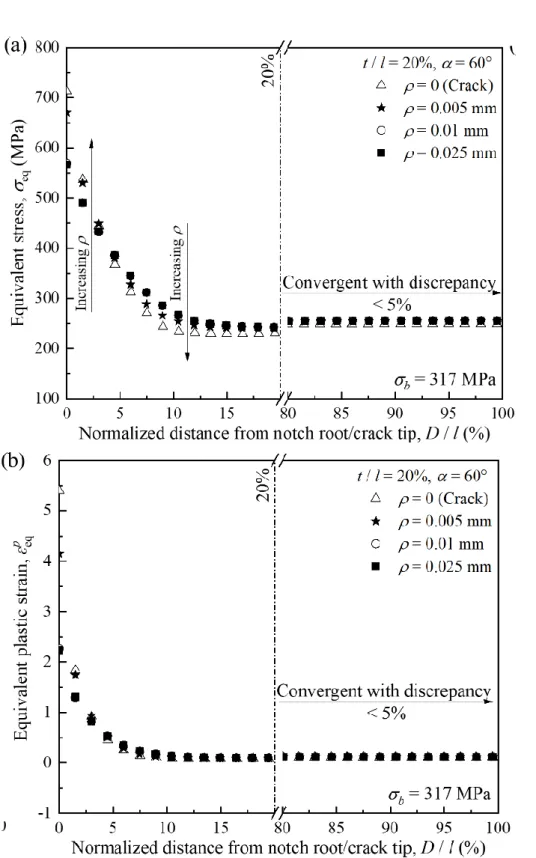
≤ 90°. Moreover, the influence of 𝛼 on 𝜎𝑏 was not dramatic compared with that of 𝜌 particularly for 𝛼 ≤ 90°. Hence, the distribution of 𝜎eq and 𝜀eq𝑝 as a response to the variations of 𝜌 with a fixed 𝛼 = 60° were compared in Fig. 2.6 to investigate the potential cause of the crack-like notch. The distribution of 𝜎eq and 𝜀eq𝑝 in the remote place of notch root were convergent to those of the pre-cracked section with a discrepancy of 5%. The discrepancy was obtained by calculating the percentage of elastoplastic fields difference between notched and pre-cracked cross-sections in the reference value of elastoplastic fields of pre-cracked cross-section. The distribution of 𝜎eq and 𝜀eq𝑝 close to the notch root and crack tip had some differences compared with those close to the crack tip. However, these differences did not occupy most of the area in the notched cross-section. Furthermore, as shown in Fig. 2.6(a), the gradient distributions of 𝜎eq close to the notch root and crack tip crossed over each other, This suggests the possibility of an identical overall work hardening in the net cross-sections when 𝜌 was smaller than a critical value, as illustrated in Fig. 2.7(a), which shows that the values of 𝐻̅ in notched and pre-cracked sections were similar. The reason is
30/121
attributed to the local strain hardening increment changing with different elastoplastic field gradient distributions, and to the different triaxial stress states generated by notch geometric variation altering the local strain hardening property. Hence, as long as the elastoplastic fields were broadly convergent in notched and pre-cracked cross-sections, the disturbance from ρ < 0.025 mm could be ignored.
Fig. 2.5 Response of tensile strength, 𝜎𝑏, to variations of notch root radius, 𝜌, and notch opening angle, 𝛼, at 𝑡/𝑙 = 20 % obtained by FEA.
31/121
Fig. 2.6 Distributions of equivalent stress, 𝜎eq, and equivalent plastic strain, 𝜀eq𝑝 , responding to variations of notch root radius, 𝜌.
The experimental results are in good agreement with the results obtained by FEA.
Fig. 2.7(b) shows the 𝜎𝑏 of the notched specimens plotted against the (elastic) stress concentration factor [84], 𝐾t . Although 𝐾t significantly varied with 𝜌 , 𝜎𝑏 was
32/121
approximately a constant. The case of 𝑡/𝑙 = 20% was taken as a typical example to analyze in detail. The engineering stress-strain curves of these specimens also coincided with each other, as shown in Fig. 2.8. Some differences exist in the post-necking elongation are attributed to that the variation in notch root radius combined with the processing error that only has limited effect during the stage of damage accumulating massively. They are insignificant for determining whether plastic instability occurs under the same boundary conditions.
Moreover, the damage patterns of these specimens are similar, as shown in Fig. 2.9.
The round dimples (indicated by the yellow line) located at the center of fracture surface are large in size and equiaxed in shape. Their appearance requires a circumstance that owns good ductility with the domination of normal strain [85,86]. Hence, these large equiaxed dimples were probably formed at the early stage of the post-necking elongation, where the ductility was not severely deteriorated by strain hardening and damage initiation, and the deformation path was not deflected significantly by necking.
They were surrounded by parabolic dimples and deep elongated dimples, most of which deflect toward the center of fracture surface by shearing and tearing of internal crack propagation. Also, the shear-lips located at the outside edge of fracture surface, which were formed by internal crack connecting with the pre-crack through shear banding, indicate the final rupture position [17]. In general, the experimental results are in good agreement with the FEA results.
![Fig. 1.2 Correlation map of fracture toughness vs. strength used in selecting material for damage- damage-tolerant design [20]](https://thumb-ap.123doks.com/thumbv2/123deta/9786786.1869972/11.892.161.728.111.545/correlation-fracture-toughness-strength-selecting-material-damage-tolerant.webp)