九州大学学術情報リポジトリ
Kyushu University Institutional Repository
Study on nanostructured electrocatalysts for oxygen reduction reaction in polymer
electrolyte fuel cells
朴, 佳榮
https://doi.org/10.15017/1866303
出版情報:九州大学, 2017, 博士(工学), 課程博士 バージョン:
権利関係:
Study on nanostructured electrocatalysts for oxygen reduction reaction in polymer
electrolyte fuel cells
Kayoung Park
A Dissertation
for the Degree of Doctor of Engineering at
Department of Materials Process Engineering Graduate School of Engineering
Kyushu University
2017
Contents
1. Introduction ... 1
1.1 Fundamentals of polymer electrolyte fuel cells ... 1
1.2 Challenges of conventional Pt catalysts ... 3
1.3 Cathode electrocatalyst approaches ... 7
1.3.1 Pt-based catalysts ... 7
1.3.2 Support materials for Pt catalysts ... 10
1.3.3 Non-Pt metal catalysts ... 14
1.4 Cathode catalysts on the durability aspects... 18
1.4.1 Pt-based catalysts on the durability aspects ... 19
1.4.2 non-Pt catalysts on the durability aspects ... 20
1.5 Objectives and approach of thesis ... 22
1.6 Thesis outline ... 25
References ... 26
2. Development of carbon nanofiber with high tolerance to sintering as a support for Pt-based catalysts ... 34
2.1 Introduction ... 34
2.2 Experimental ... 37
2.2.1 Formation of CNFs ... 37
2.2.2 Preparation of supported Pt catalysts ... 38
2.2.3 Characterization of Pt-based catalysts ... 39
2.2.4 Electrochemical measurement of the catalysts ... 40
2.3 Results and discussion... 41
2.3.1 Characterization of carbon supports ... 41
2.3.2 Preparation of Pt catalysts supported on CNF ... 45
2.3.3 Preparation of Pt-Co alloy catalysts ... 54
2.3.4 Electrocatalytic performance of Pt-Co/CNF(HNO
3) ... 61
2.4 Conclusions ... 62
References ... 63
3. Carbon-supported V-Mo oxides catalysts for oxygen reduction reaction ... 68
3.1 Introduction ... 68
3.2 Experimental ... 70
3.2.1 Preparation of catalysts ... 70
3.2.2 Electrochemical measurements ... 71
3.2.3 Characterization of catalysts ... 72
3.3 Results and discussion... 72
3.3.1 Catalytic activity of Mo-based oxide catalysts for the ORR ... 72
3.3.2 Electrochemical measurement of V-Mo oxide catalysts ... 76
3.3.3 Characterization of V-Mo oxide catalysts ... 79
3.4 Conclusions ... 81
References ... 82
4. Carbon-supported Pd-Ag catalysts with silica-coating layers as active and
durable cathode catalysts for polymer electrolyte fuel cells... 84
4.1 Introduction ... 84
4.2 Experimental ... 86
4.2.1 Preparation of catalysts ... 86
4.2.2 Characterization of catalysts ... 87
4.2.3 Electrochemical measurements ... 88
4.3 Results and discussion... 89
4.3.1 Pd-based catalysts ... 89
4.3.2 Pd-Ag/CB catalysts ... 91
4.3.3 Improvement in durability of Pd-Ag/CB by coverage with silica layers ... 98
4.4 Conclusions ... 103
References ... 103
5. Conclusions and future works ... 106
5.1 Conclusions ... 106
5.2 Future works ... 108
ACKNOWLEDGEMENT ... 110
Chapter 1 Introduction
1.1 Fundamentals of polymer electrolyte fuel cells
The alternative energy sources have been demanded for the past few decades due to the increasing consumption of energy resources, the high cost of energy, the continuous and rapid depletion of fossil fuels, and the environmental problems such as emission of harmful pollutants like CO
2, NO
x, SO
x. Fuel cells convert chemical energy directly into electric energy with fuel and oxidant, resulting in high efficiency, low emissions, and low environmental impact. Consequently, fuel cells are a very attractive alternative device [1–
4]. In particular, polymer electrolyte fuel cells (PEFCs) as one of the fuel cells can be applied to fields such as portable electronics, vehicles, and combined heat and power (CHP) system etc. In addition, the PEFCs have been actively developed due to their low operating temperature in range of 20 ~ 100 ℃ , simplicity, high power density, and quick start-up [5]. These PEFC’s systems are composed of stack which means a number of single cells in series and some components such as fuel processor, humidifiers, air compressors, and power conditioners, etc [6,7]. The single cell of PEFCs is shown in Fig.
1.1. The PEFCs consist of a membrane electrode assembly (MEA), two bipolar plates as
separators, and two seals. The MEA which is known as a critical component of PEFC is
comprised of a proton exchange membrane (PEM) which is usually Nafion
○R, two
dispersed catalyst layers (anode and cathode), and two gas diffusion layers which offer the fuels and oxygen (air). Hydrogen oxidation reaction (HOR) and oxygen reduction reaction (ORR) occur at the anode and cathode in the MEA, respectively. The membrane allows protons to pass through to complete the overall reaction while it separates the half reactions at the anode and cathode [8]. The electrons also flow through an external load circuit from the anode to the cathode. During operation of PEFCs, the oxygen molecule is reduced by the protons and electrons, resulting in the generation of water, electricity, and heat. The theoretical open circuit voltage is given as 1.229 V where both HOR and ORR simultaneously occur. However, the PEFCs generate the lower actual voltage than 1.229 V due to their overpotential or irreversible voltage losses. Figure 1.2 shows voltage losses of PEFCs [6]. Activation losses at low current density give rise to significant voltage drop and occur primarily at the cathode because reaction rate of the ORR on the
A n o d e C at h o d e
G a s D iff u s io n L a y e r G a s D iff u s io n L a y e r
B ip o la r P la te B ip o la r P la te
P E M
H
+e
-e
-E n d P la te E n d P la te
MEA
H
22H
++ 2e
-O
2+ 4H
++ 4e
-2H
2O
Fig. 1.1 Schematic diagram of PEFCs.
cathode is much slower than that of the HOR on the anode. Fuel crossover/internal current losses associated with the electrolyte also take place at low current densities by either fuel leaking or electrons leaking through the electrode. In the Fig. 1.2, voltage falls more slowly and graph is fairly linear as results of ohmic losses which are generated by electrical resistance of the electrodes and the resistance to the flow of ions in the electrolyte. Voltage then begins to fall faster at higher currents caused by the mass transport/concentration losses. These losses affect the theoretical voltage, which results in the degradation of their performance in the PEFCs [6,9].
1.2 Challenges of conventional Pt catalysts
As mentioned above, the oxygen reduction reaction (ORR) occurs at the cathode. The
Fig. 1.2 Voltage losses of PEFCs [6].
ORR has two pathways including direct four-electron reaction and a series of two- electron reaction, respectively. In the direct 4-electron pathway, O
2is directly reduced to H
2O (Eq 1), which offers higher operation potentials and current efficiency in the PEFCs.
In contrast, the two-electron reaction takes place at low potential and produces H
2O
2as an intermediate by-product (Eq 2). The produced H
2O
2is reduced to H
2O (Eq 3). The formation of H
2O
2at cathode results in oxidative degradation of the membrane.
O
2+ 4H
++ 4e
-→ H
2O 1.229 V vs. NHE (1) O
2+ 2H
++ 2e
-→ H
2O
20.70 V vs. NHE (2) H
2O
2+ 2H
++ 2e
-→ 2H
2O 1.76 V vs. NHE (3)
The direct 4-electron reaction of O
2is thus preferred, resulting in high ORR activity, as compared to the series of two-electron reaction. The most commonly used metal catalyst for the ORR at the cathode is Pt catalyst due to their efficient ORR ability [11–
14]. However, the Pt cathode catalysts are facing the problems that are related to their
degradation. The degradation of the Pt catalysts takes place under severe cathode
conditions such as low pH value, high temperature, highly positive potential, high
humidity, and oxidant feeds, which result in catalytic activity loss [15]. Figure 1.3 shows
simplified mechanisms of Pt degradation on a carbon support in the PEFCs. The Pt
degradation is divided into various processes : (i) dissolved Pt ion transport in the ionomer
phase and then reprecipitation by H
2crossover through the membrane, (ii) Ostwald
ripening on the carbon support, (iii) coalescence of Pt nanoparticles via Pt crystal
migration on the carbon support, and (iv) detachment and agglomeration of Pt
nanoparticles from the carbon support [16–20]. These processes of Pt degradation can
distinguish conceptually between primary and secondary degradation phenomena. The Pt dissolution as a primary degradation process can induce secondary processes such as Pt deposition in the ionomer or Ostwald ripening. Moreover, carbon corrosion is another primary degradation phenomenon which causes secondary degradation processes such as Pt particle detachment or agglomeration [18]. These degradation phenomena of the Pt catalysts eventually reduce their catalytic activity. In particular, during start-stop cycles of PEFCs, severe activity loss of Pt catalysts is caused by such Pt degradation phenomena due to their instability, which results in a decrease of durability. In other words, to prevent the Pt degradation, the stability of the Pt catalysts is an important factor for high performance fuel cells under the severe cathode conditions [21]. Therefore, more stable Pt or non-Pt cathode catalysts, which can replace the conventional Pt catalysts, should be developed to avoid the degradation of catalysts under severe cathode conditions. However, the challenge of cathode catalysts has yet to be solved.
Agglomeration
Carbon Support
Pt Pt Pt Pt Pt
Pt
Pt
Pt Dissolution
Ostwald Ripening CO
2Carbon Corrosion
Pt Pt Pt
Pt PtPt Pt Pt
Pt
Pt
Pt Pt PtPtPtPt Pt
Pt
Pt redeposition Particle Detachment
PtPt Pt
Pt diffusion across a membrane
Fig. 1.3 Simplified mechanism of Pt degradation on a carbon support in the fuel cells.
One of the most challenging problems is high cost of PEFCs for commercialization, which can be attributed to cathode catalysts. Recently, Adria Wilson et al. reported on 2016 projected cost of 80-kWnet transportation fuel cell stacks and systems depending on system units per year. Stack cost (153 $ / kWnet) at 1,000 units/year accounted for approximately 71 % of total system cost (215 $ / kWnet), while stack cost (27 $ / kWnet) at 500,000 units/year formed about 52 % of total system cost (53 $ / kWnet). Namely, an increase in the number of system units reduced the total system cost with a decrease in the percentage of the stack cost. Figure 1.4 shows a breakdown of stack component cost depending on the number of system units. The stack cost at 1,000 systems/year is dominated by two components such as membrane and (catalyst + application). When production volume of fuel cell systems increases from 1,000 to 500,000 systems/year, the percentage of the membrane decreases from 26 % to 8 % in fuel cell stack cost. In contrast, the part of (catalyst + application) increases from 23% to 43 % with rising in the systems despite decrease in the stack cost at 500,000 systems/year. This is caused by the cost of Pt metals used as catalysts in the both electrodes for PEFCs [22]. It was reported that the Pt metal, average monthly calculation, significantly increased from the price of $1234 per ounce for 2007 to $1724 per ounce for 2011 and then decreased the Pt price of $ 993 per
Fig. 1.4 A breakdown of stack component cost depending on the number of system
ounce for 2016 as for trend of the Pt price in the market. These trends of the Pt price are variable so that one can have an effect on the cost of fuel cell systems [23]. To commercialize the PEFCs, it is necessary to reduce the utilization of Pt or develop non- Pt catalysts which can meet the higher performance than the conventional Pt catalysts. In order to solve the challenges of the conventional cathode catalysts, more efficient, inexpensive, and stable electrocatalysts are required.
1.3 Cathode electrocatalyst approaches
A number of cathode catalysts have been developed to solve the challenges of the conventional Pt catalysts. These studies can be classified into three groups such as Pt- based catalysts, supporting materials, and non-Pt metal catalysts.
1.3.1 Pt-based catalysts
One of the most common Pt-based catalysts to reduce utilization of the Pt is by alloying Pt and transition metals such as Co, Mn, Ni, Fe, and Cu, which are designed for binary alloys or ternary alloys as potential candidates [24–28]. A substantial amount of researches have been carried out over the past decades on carbon-supported binary alloys or ternary alloys which demonstrate 2 ~ 3 times higher mass activity compared to the commercial Pt catalysts. In addition, the ORR activity of these Pt-alloy catalysts such as Pt-Co, Pt-Ni, Pt-Fe, Pt-Cr, Pt-V, Pt-Ti, Pt-W, Pt-Al, and Pt-Ag has been improved by the shorter Pt-Pt bond distances and the structure-sensitive inhibiting effects of OH
ads[29,30].
Due to the highest possible Pt utilization, core-shell catalyst which is composed of Pt
located only on the surface of nanoparticles of another metal is highly attractive from a cost perspective. In particular, the largest potential advantage of such core-shell catalyst design is the extraordinarily high electrochemically active surface area (ECSA) caused by the high Pt dispersion [29]. Wang et al. demonstrated that prepared Pt-Co core-shell nanoparticles were comprised of ordered Pt
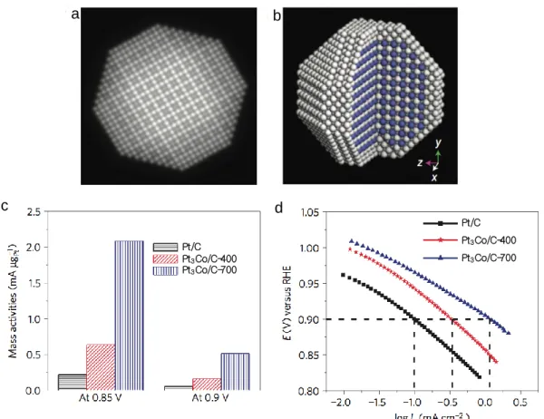
3Co intermetallic cores with a 2~3 atomic layer thick Pt shell and showed impressive activity. Idealized Pt-Co nanoparticles are shown in Fig. 1.5a-b. As comparison of mass activities (Fig. 1.5c), carbon-supported
a b
c d
Pt/C Pt3Co/C-400 Pt3Co/C-700 Pt/C
Pt3Co/C-400 Pt3Co/C-700
Fig. 1.5 (a) Multislice simulated ADF-STEM image of the idealized nanoparticle.
(b) The idealized atomic structure of the Pt
3Co core–shell nanoparticle and,
white and blue spheres present Pt and Co atoms, respectively. (c) Comparison
of mass activities for Pure Pt and Pt-Co alloy nanoparticles at 0.85 and 0.9 V
and (d) comparison of specific activities (I
k) [31].
Pt
3Co nanoparticles after heat-treatment at 700 ℃ (denoted as Pt
3Co/C-700) exhibit one of the highest electrocatalytic activities for the ORR. Figure 1.5d also presents the specific activity of Pt
3Co/C-700 is 1.1 mA cm
-2at 0.9 V, which is much higher than those of pure Pt and Pt
3Co/C-400 (after heat-treatment at 400℃). This high activity is attributed to the Pt-rich shell as well as the stable intermetallic Pt
3Co core arrangement, which arise from the strain put on the Pt surface via lattice mismatch resulting in the Pt
3Co with the smaller lattice constant than Pt shell. So far, this mass activity for the ORR is the highest among the Pt-Co systems reported in the literature under similar testing conditions [31]. As other studies, shape-controlled catalysts also show a highly promising class of ORR catalyst due to their extremely high mass activities. Stamenkovic et al. demonstrated that the Pt
3Ni(111) surface is 10 times more active for the ORR than the corresponding Pt(111) surface and 90 times more active than the current-of-the-art commercial Pt/C catalysts for PEFC. The Pt
3Ni(111) surface has an unusual electronic structure (d-band center position) and arrangement of surface atoms in the near-surface region. Under operating conditions relevant to fuel cells, its near-surface layer exhibits a highly structured compositional oscillation in the outermost and third layers, which are Pt-rich, and in the second atomic layer, which is Ni-rich. The weak interaction between the Pt surface atoms and nonreactive oxygenated species increases the number of active sites for O
2adsorption [32]. Interestingly, Pt-based nanoframe showed significantly higher mass activity up to 20 times than commercial Pt/C based on RDE studies. Particularly, the largest advantage of such nanoframe is their superb stability and durability during voltage cycling [28,29].
Chen et al. synthesized a highly active and durable class of electrocatalysts by exploiting
the structural evolution of Pt-Ni bimetallic nanocrystals. The synthesized Pt
3Ni
nanoframe catalysts achieved 36-fold enhancement in the mass activity and 22-fold enhancement in the specific activity, respectively, for the ORR (relative to state-of-the- art Pt/C) during prolonged exposure to reaction conditions [33].
1.3.2 Support materials for Pt catalysts
Carbon blacks have been widely used as support materials for PEFC catalysts due to their high electrical conductivity, affordability, and accessibility, relatively high chemical and electrochemical stability [34]. However, when it is used as supports for the Pt or Pt- based alloy catalysts, the carbon black suffers from carbon corrosion under the severe cathode conditions, leading to the Pt degradation which results in the lower performance.
This is caused by weak interaction between support and nanoparticles. When the carbon blacks with an average pore diameter below 2 nm are used as supports for Pt or Pt-based alloy catalysts, supply for a fuel to the catalyst layer may not be smooth and efficient, and the catalytic activity starts to be limited by mass transfer. Furthermore, it is known that micropores of amorphous carbon particles are poorly connected. To solve the problems for carbon blacks as the supports, many support materials have thus been developed [35–
39]. One of the common support materials is carbon material including carbon nanotubes
(CNTs), carbon nanofibers (CNFs), graphene, ordered mesoporous carbon, and carbon
nanocages. Mesoporous carbons with the range of 2 to 50 nm of pore diameter present
important porous features such as pore connectivity, pore size, distribution, and pore
length, which can influence catalytic performance [14,40–44]. In addition, the
mesoporous carbons have high surface area and few or no micropores, and high distribution of Pt or Pt-alloy nanoparticles and result in a largely effective Pt surface area with high catalytic activity. The mesoporous structures also facilitate smooth mass transport, yielding high limiting current values. In particular, the support materials with high graphic nature (e.g. CNFs and CNTs) among the various mesoporous carbons are reportedly more stable [1,45]. Both CNFs and CNTs also possess the unique surface structures, excellent mechanical and thermal properties, and high electric conductivity and surface area. Many types of CNTs and CNFs are shown in Fig. 1.6. The CNTs are classified as single-wall CNT (SWNT) and multi-wall CNT (MWNT). The SWNT is a
Armchair Zig-Zag type Helical type
Platelet type Tubular type Fishbone type
Carbon nanotubes
Carbon nanofibers (a) (b)
(c)
Fig. 1.6 Schematic representations of (a) single-wall CNTs and (b) multi-wall
CNTs, and (c) three types of CNFs [46,47].
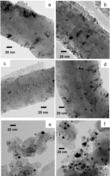
seamless cylinder enclosed by a single graphene sheet. The MWNT can be considered as a concentric SWNT with an increasing diameter and is coaxially disposed. On the other hands, CNFs are well known as platelet, tubular, and fishbone types. The platelet type CNF has graphene layers perpendicular to the growth axis. The tubular type CNF has graphene layers parallel to the growth axis with multi-wall assembly. The fishbone type CNF also has graphene layers with an angle of 45° to the growth axis [46,47]. These graphic carbons are expected to offer great potential for catalyst supports. However, it is necessary to modify their surfaces via various methods such as non-covalent polyelectrolyte functionalization or strong oxidation because the graphic carbons are relatively inert [34,48,49]. Guha et al. reported that modified CNF as functionalized graphitic carbon by concentrated acid treatment showed the higher performance than activated carbons as amorphous carbons and is comparable to the commercial Pt catalysts during single cell test because the CNFs have the lower ohmic losses than the activated carbons measured by electrochemical impedance spectroscopy (EIS) [50,51]. In addition, Sebastián et al. investigated three different CNFs with varying in terms of average diameter, ordering degree, and surface structure as Pt supports for the cathode in PEFCs.
These three different CNFs were prepared by different temperatures using catalytic
chemical vapor deposition method. Dispersion of Pt on Vulcan (carbon blacks) does not
appear better than that of CNF as shown in Fig. 1.7a-d. Among the CNF-supported
Pt(Pt/CNF) catalysts, Pt catalyst supported on the CNF prepared at 650 ℃ (Pt/CNF650)
showed the highest ECSA values due to its best compromise in terms of support surface
area and dispersion of Pt as resulting from a moderate concentration of surface groups in
the support in Fig. 1.7e. In contrast, carbon black supported Pt catalyst and Pt catalyst
supported on the CNF prepared at 550 ℃ (Pt/CNF550) presented very low mass activities,
which was caused by a large number of support surface groups and defects. The highest performance was also obtained both before and after the accelerated degradation tests for the Pt/CNF650 catalysts, which is attributed to the highest ECSA and proper graphitic character of the support [36]. Similarly, it was observed that graphitic CNT(GCNT)
(e)
Fig. 1.7 TEM micrographs of (a) Pt/CNF550, (b) Pt/CNF650, (c) Pt/CNF700, and
(d) Pt/Vulcan and (e) their mass activities in the ORR before and after Pt
degradation from polarization curves at 0.80 V vs. RHE [36].
supported Pt catalysts showed enhanced ORR activity, which was attributed to the high graphitization degree of GCNTs as well as the high electrochemical surface area of Pt nanoparticles [52]. Consequently, such carbon material supports including specialized CNT, CNF, graphene, and other types of carbon material supports do offer improved ORR activity, compared with the conventional carbon black [14]. On the other hand, non- carbon materials including titanium oxides, cerium oxide, niobium oxide, tungsten oxide, some carbides, nitrides, oxynitrides, borides, and conductive polymers also have been developed [34,53–55]. Titanium dioxide as one of non-carbon materials presents high chemical and electrochemical stability, along with strong interaction with metal nanoparticles, showing great potential as an alternative support material for PEFCs [14].
Huang et al. reported that a novel TiO
2-supported Pt electrocatalyst (Pt/TiO
2) showed excellent fuel cell performance due to its low mass transport limitation in the cathode catalyst layer. The Pt/TiO
2also had an ultrahigh stability compared to the conventional Pt catalyst, which can be attributed to a strong metal support interaction between the Pt particles and TiO
2support [56].
1.3.3 Non-Pt metal catalysts
Non-Pt metal catalysts with various types of active components have been studied
due to their potential to greatly reduce cost as well as overcome limitation of the
commercial Pt catalysts having insufficient performance, stability, and durability. Recent
non-Pt metal catalysts have demonstrated sufficient performance to be considered for use
in certain nonautomotive applications such as backup power and/or portable power,
which have significantly lower performance, stability, and durability requirements than
automotive applications [29].
One of the non-Pt metal catalysts is by using Pd as the main metal. Pd, it is much less costly than Pt, has similar physical properties to Pt, including fcc crystal structure and a similar atomic radius. Indeed, Pd-based catalysts have been developed by either changing their structure, shape, and particle size or alloying other metals such as Co, Ni, and Au [57–59]. Electrocatalytic activities of various Pd-alloy catalysts were investigated in Fig.
1.8. Bampos et al. reported that many Pd-M (M = Ag, Co, Cu, Fe, Ni, and Zn) alloy catalysts show the different ORR activities depending on types of transition metals.
(b)
Fig. 1.8 Histograms showing at selected potentials, (a) specific activity and
(b) mass activity [60].
Among the tested Pd/C and Pd-alloy catalysts, the PdZn/C electrocatalyst exhibited significantly higher specific activity and similar mass activity compared to Pt/C. In particular, the specific activity of the PdZn/C was 2.8 ~ 3.3 times higher than that of Pt/C, whereas its mass activity was slightly lower at 0.35 V vs. Ag/AgCl and slightly higher for 0.4 – 0.5 V vs. Ag/AgCl. This clearly demonstrates the superiority of the PdZn/C over the Pd/C [60]. In addition, Kondo et al. reported the ORR activity trend on the low index planes of Pd. It was observed that the current density of the ORR on Pd(100) was nearly three times as high as that on Pt(110) at 0.90 V vs. RHE, indicating that Pd(100) structure is the active site for the ORR on Pd electrodes [57].
Some researches on metal chalcogenides catalysts, mainly Se or S-based, have attracted significant attention since Alonso-Vante and Tributsch discovered that Ru
2Mo
4Se
8had the ORR activity comparable to Pt in aqueous H
2SO
4. The metal chalcogenides catalysts including S, Se, and Te showed good ORR activity [5,61–63].
Fig. 1.9 Ball and stick diagrams showing (A) Kegging (B) Wells-Dawson HPA
variants where, phosphorus atoms are black, addenda atoms are dark [64].
Heteropolyacids (HPAs)-based catalysts have been attracting attention because of their unique structures which are capable of the ORR via oxidation and reduction (redox).
Typical HPAs contain Keggin (H
nXM
12O
40) and Wells-Dawson (H
nX
2M
18O
62) structures composed of a particular combination of hydrogen and oxygen with heteroatoms (X) such as P or Si and addenda atoms (M) W, Mo, and V as shown in Fig. 1.9 [64]. These HPAs as fuel cell catalysts have an advantage because they can simplify the ionomer needs of the electrode and theoretically reduce the complexity of the three phases boundary.
Moreover, it is known to be stable under the high voltages and low pH conditions which are similar to the PEFC cathode conditions. These HPAs can go through multiple reversible 1 or 2e
-reductions while still retaining their structure. In particular, the HPAs with Mo addenda atoms can produce steady and significant current densities due to their outstanding redox abilities. This high activity for the ORR on the HPA-based catalysts may be caused by the HPA to be reduced by 4e
-. In addition, the potential where the HPA- based catalyst begins the ORR in the polarization curves can be improved by substituting two or three V atoms into the HPA structure, which positively shifted the reduction potential [64,65].
Other types of non-Pt catalysts, including carbon based-non-Pt metal catalysts and
metal-free catalysts, also have been reported. It was found that either Fe- and/or Co-based
catalysts show interesting properties for the ORR [14,66]. Lefèvre et al. produced
microporous carbon-supported Fe-based catalysts(Fe/N/C) with active sites including Fe
cations coordinated by pyridinic nitrogen functionalities in the interstices of graphitic
sheets within the micropores. The synthesized Fe/N/C catalysts showed the best current
density among all Fe-based electrocatalysts reported in the paper and also were equal to
Pt-based cathode with a Pt loading of 0.4 mg cm
-2at 0.9 V [67]. Other research groups
reported that metal oxide catalysts, particularly group 4 and 5 metals, in the form of metal nitrides and oxynitrides, and metal carbonitrides. The metal oxide catalysts have definite catalytic activity for the ORR due to their chemically good stability in acidic electrolytes [68,69]. Chisaka et al. recently demonstrated the successful syntheses of zirconium oxynitride (ZrO
xN
y) catalysts on multi-walled carbon nanotubes. The catalyst showed the highest ORR activity among other oxide-based catalysts tested by his research group. In addition, the single-cell performance of these ZrO
xN
ycatalysts presented 10 mA cm
-2at 0.9 V. Such a high performance has never been reported for Fe-free oxide-based catalysts so far, indicating that the ZrO
xN
ycatalysts are suitable ORR catalysts for real PEFC cathodes [70].
1.4 Cathode catalysts on the durability aspects
Durability of cathode catalysts is thought to be one of major problems inhibiting the commercialization of PEFCs. The durability is also one of the important factors that can determine lifetime of the PEFCs. Improving the durability for such cathode catalysts thus can lengthen the lifetime of PEFCs, enhance the reliability and reduce the total lifetime cost [71]. However, the durability is reduced by Pt degradation on the Pt-based catalysts and instability of non-Pt-based catalysts under harsh cathode conditions. To solve the reduction in the durability, the researches on the durability of cathode catalysts including both Pt- and non-Pt based catalysts have been reported.
As one of the methods to enhance the durability of the cathode catalysts, silica-coating
of Pt or Pd-based catalysts has been developed in our laboratory. We have previously
covered CB or CNT-supported metal particles such as Pt and Pd with silica layers. These
silica-coated metal catalysts showed excellent durability because the silica layers around the metal particles prevent the migration of metal particles on the CB or CNT supports and the diffusion of dissolved metal cations out of silica layers under the cathode conditions. Thus, the silica-coating method was our study on the improvement of durability for Pd-Ag catalysts described as chapter 4 [72–75].
1.4.1 Pt-based catalysts on the durability aspects
The conventional Pt catalysts have experienced the Pt degradation including the increase in Pt nanoparticle size or/and the Pt dissolution into an electrolyte, or/and the detachment of the Pt from carbon support, which result in deterioration of the performance following the loss of ECSA during the PEFC operation as shown in Fig. 1.10 [17,71]. Thus, strategies to enhance the durability such as alloying Pt with another metals and development of catalyst supports have been proposed in the Pt-based catalysts. Some approaches have reported that Pt alloy catalysts with a second and/or third metal such as Pt
3Ni/C, Pt-Fe alloy, Pt
4ZrO
2/C, and Pt
6Co
1Cr
1/C showed improved durability, which is attributed to an anchor effect between Pt and another metals [32,76–78]. Zhang et al.
demonstrated that Au/Pt/C catalysts by modifying Pt nanoparticles with gold (Au)
clusters can be stabilized against dissolution under potential cycling between 0.6 and 1.1
V vs. RHE in over 30,000 cycles, which results in no loss of activity. The Au clusters
confer stability by raising the Pt oxidation potential [79]. Development of carbon
materials with high graphic nature such as CNT and CNF that can be used as substitute
for the carbon black also is one of methods for improvement of durability. An increase in
the degree of graphitization leads to stronger π sites (sp
2-hybridized carbon) on the
support, which acts as anchoring sites for Pt, thus strengthen the metal-support interaction
and the resistance of Pt to sintering [71]. Recently, Ando et al. demonstrated that Pt/TiO
2/cup-stacked CNT (CSCNT) composite catalysts met high catalytic activity and high durability for the ORR. In particular, the Pt/TiO
2/CSCNT composite showed no change in the Pt particle size of 3.4 nm after 2000 potential cycling between 0.05 V and 1.1 V vs. RHE as well as 1.0 V and 1.5 V vs. RHE, respectively. This result indicates that for the Pt/TiO
2/CSCNT composite, TiO
2matrix composed of Ti oxides and CSCNT anchors the Pt nanoparticles, which prohibits them from aggregating and consequently the durability is improved [80].
1.4.2 non-Pt catalysts on the durability aspects
Prior to 2009, very few publications discussed the cycling durability of non-Pt catalysts, which primarily reported stability data (performance loss during potentiostatic experiments). However, as significant advances have brought the activity of these non-Pt catalysts to a stage where they are becoming industrially relevant, the requirement for durability during voltage cycling has attracted more attention. Thus, since 2009, there have been many reports focusing on the cycling durability of the non-Pt catalysts. Despite many reports on the durability of the non-Pt catalysts, the non-Pt catalysts are still widely observed to suffer from extremely poor stability. The mechanism for the poor stability of the non-Pt catalysts is not known with certainty, and takes place by metal dissolution or leaching of the active metal site, oxidative attack by H
2O
2, and protonation of the active site [81] . To obtain high stability, many approaches have been proposed. Peng et al.
reported Fe- and N- doped carbon catalyst Fe-PANI/C-Melamine with graphene structure.
It was found that after 10,000 cycles, the activity decreased by ~ 27%. They highlighted
the fact that the Fe-PANI/C-Melamine showed less activity loss at both the low potentials
and high potentials after the accelerated test cycling [82].
The Pd-based catalysts also have been reported for their durability. Despite Pd metal possesses high activity for the ORR, the Pd-based catalysts have poor stability and durability because Pd is easily dissolved in an acidic electrolyte for PEFCs. As one of the methods to improve the durability of Pd-based catalysts, alloying with certain elements thus has been suggested [83]. Some researches including Pd-Mo, Pd-Co-Mo, Pd-Ti, Pd-
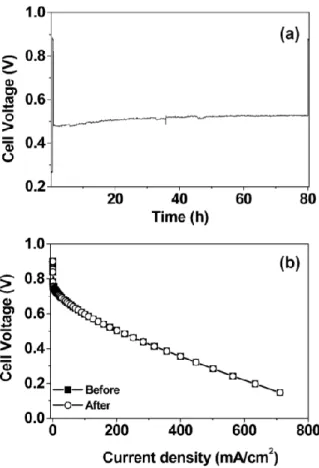
Fig. 1.10 Stability evaluation of Pd-Co-Mo/C (Pd:Co:Mo = 70:20:10 atom %)
cathode upon polarizing the cell at 200 mA/cm
2for 80 h in a single cell
PEMFC at 60 °C with a metal(s) loading of 0.2 mg/cm
2: (a) cell voltage
variation during the time of polarization and (b) steady-state polarization
curves before and after polarization. The current density values are with
respect to the geometrical area.
Co-Au have reported that alloying Pd with another metal results in the improved stability [84–86]. Figure 1.10 shows a stability assessment for Pd-Co-Mo catalysts by recording the cell voltage with time (Fig. 1.10a) and the polarization curves before and after polarizing the fuel cell at a constant current density of 200 mA cm
-2for 80 h (Fig. 1.10b).
The cell exhibits stable voltage within this test period (Fig. 1.10a) without any difference in the curves before and after polarizing the cell (Fig. 1.10b), indicating excellent stability for the Pd-Co-Mo catalysts [85].
1.5 Objectives and approach of thesis
The objective of this thesis is to develop new cathode electrocatalyst technologies that are able to improve the performance and durability of PEFCs with reducing the Pt loading.
To achieve the objective of this thesis, a new strategy was required. Our new strategies are related to development of support materials for Pt or Pt-alloy catalysts and non-Pt metal catalysts. Figure 1.11 shows the individual research area of this thesis.
To reduce the Pt loading, we firstly focused on Pt-based alloy catalysts due to their
excellent catalytic activity toward ORR when compared to pure Pt catalysts [87]. The Pt-
based alloy catalysts should be treated at high temperatures for the enhancement of their
alloying degree, which leads to aggregation of the alloy particles due to weak interaction
between carbon black and alloy particles. Thus, we investigated many carbon materials
such as carbon nanotubes (CNTs) and carbon nanofibers (CNFs) as a new support for Pt-
based alloy catalysts, which should be capable of stabilization of metal particles during
the treatment of the catalysts at high temperatures. We chose the fishbone-typed CNFs,
which possess high mechanical and chemical stability, and high surface area, due to the
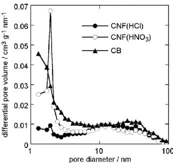
higher yields and metal dispersion compared to CNTs [88,89]. To utilize the CNFs as the support for the Pt-based alloy catalysts, the CNFs are usually treated with oxidants because the surface of the CNFs is chemically inert. Oxygen- containing functional groups such as –COOH and –OH are introduced by the treatment with oxidants. However, the functional groups on the CNF surfaces are easily decomposed at high temperatures [90]. Thus, we considered the formation of porous structures in the CNFs which are capable of anchoring metal particles in the pores by using the treatment for elongated period of the CNFs with concentrated HNO
3. It was expected that the introduction of porous structures in the CNF supports, which is attributed to continuous carbon oxidation on the CNFs, inhibits the migration of metal nanoparticles on the surface of the CNFs at high temperatures. In addition, we thought that the Pt-based alloy catalysts with high tolerance to sintering of alloy nanoparticles can show the higher activity for the ORR compared to carbon black-supported Pt-based catalysts.
Non-Pt metal catalysts
Mo-based oxide catalyst Pd-based catalyst
High ORR Activity and Durability
New support for Pt-based catalyst
Carbon nanofiber


![Fig. 1.8 Histograms showing at selected potentials, (a) specific activity and (b) mass activity [60]](https://thumb-ap.123doks.com/thumbv2/123deta/9918547.1919715/21.892.263.683.144.716/fig-histograms-showing-selected-potentials-specific-activity-activity.webp)