Diesel and Bio-diesel Fuel Deposits
on a Hot Wall Surface
A THESIS
Submitted by
YUSMADY BIN MOHAMED ARIFIN
In partial fulfillment of the requirements for the award of the Degree of
DOCTOR OF PHILOSOPHY IN
MECHANICAL SYSTEM ENGINEERING
Under the guidance of
PROFESSOR MASATAKA ARAI, Ph. D. Eng.
DEPARTMENT OF MECHANICAL SYSTEM ENGINEERING GUNMA UNIVERSITY
JAPAN
i
Acknowledgement
Special thanks to my supervisor Professor Dr. Masataka Arai for his great
guidance and support. Without his support this study could not have been done
properly.
I would like to thank Dr. Tomohiko Furuhata, Mr. Masahiro Saito and Mr. Goro
Ogiwara for their advice and support during my study.
My appreciation also goes to members of the engine deposition test group, Mr.
Yutaka Tsuruta, Mr. Yoshinori Kodaira and Mr. Naoyuki Kanemoto for their
kindness in providing the engine data results to be analyzed in this study.
I would like to forward my gratitude to Universiti Teknikal Malaysia Melaka
(UTeM) and the Malaysian Government for providing the financial support.
Finally, I also would like to thank to my mother Ampuan Azizah and my
ii
Declaration
I hereby declare that this submission is my own work and that, to the best of
my knowledge and belief, it contains no material previously published or written
by another person nor material which has been accepted for the award of any other
degree of the university or other institute of higher learning, except where due
acknowledgement has been made in the text.
Signature:
Name: Yusmady bin Mohamed Arifin
Student No.: 06812272
iii
Table of contents
Acknowledgement i
Declaration ii
Table of contents iii
List of figures vii
List of tables x
List of abbreviations xi
Nomenclature xiii
Abstract xvi
Chapter 1
Engine deposit research: A review of the current literature
1.1 Introduction 1 1.2 Bio-diesel fuels 2 1.3 Engine deposits 6 1.3.1 Deposit origin 8 1.3.2 Deposit characteristics 10 (1) Deposit structures 10 (2) Deposit properties 14 1.3.3 Deposit mechanisms 16 (1) Formation mechanism 16 (2) Removal mechanism 18
1.3.4 Factors of deposit formation 19
(1) Liquid film formation 20
(2) Wall surface temperature 23
(3) Air/fuel ratio 25
(4) Engine operating condition 26
(5) Fuel and lubricant oil 27
1.3.5 Engine problems due to deposits 29
(1) Heat transfer in the combustion chamber 29
(2) Engine performance 30
iv
(4) Engine damage 34
1.3.6 Deposit preventive measures 34
(1) Engine parameters 34
(2) Engine design 35
(3) Deposit mechanism considerations 36
(4) Wall temperature control 37
(5) Fuel and lubricant formulation 37
1.4 Purpose of this study 38
1.4.1 Overview of recent studies 38
1.4.2 The importance of deposit investigation 40
1.4.3 Objectives of this study 41
Chapter 2
Methodology of deposition research
2.1 Introduction of the deposition test 43
2.2 Methodology and hot surface deposition test 47
2.3 Experimental apparatus and procedures 48
2.3.1 Hot surface deposition test (HSDT) 48
(1) Single droplet repetition apparatus 48
(2) Evaporation test (ET) procedures 50
(3) HSDT procedures 52
2.3.2 Engine deposition test (EDT) 55
(1) Four-stroke DI diesel engine 55
(2) EDT procedures 57
2.4 Test fuel 58
Chapter 3
A
vailability of the hot surface deposition test (HSDT)
3.1 Introduction 62
v
3.2.1 Hot surface deposition test results 63
(1) Evaporation characteristics of DF and DF blended with SAE 30 63 (2) DF and DF blended with SAE 30 depositions on a hot wall
surface 65
3.2.2 Engine deposition test results 71
(1) Heat release rate results 71
(2) DF and DF blended with SAE 30 depositions in an engine 72
3.2.3 Deposit composition of HSDT and EDT 73
3.3 Discussion 75
3.3.1 Similarity between HSDT and EDT 75
(1) Deposition results 76
(2) Test conditions 80
3.3.2 Availability of HSDT 83
3.4 Summary 84
Chapter 4
The effect of hot surface temperatures on diesel fuel deposit
formation
4.1 Introduction 85
4.2 Results 85
4.2.1 Evaporation characteristics of dodecane and diesel fuel (JIS No. 2) 85
4.2.2 Diesel fuel deposition on a hot surface 89
4.3 Discussion 91
4.3.1 Development process of DF deposits 91
(1) Classification of development tendency 91
(2) and values comparison 95
4.3.2 Surface of DF deposits 96
4.3.3 Surface temperature of DF deposits 97
4.3.4 Wet/dry conditions 99
vi
Chapter 5
Bio-blended diesel fuel deposits on a hot wall surface
5.1 Introduction 104
5.2 Results 104
5.2.1 Evaporation characteristics of bio-blended diesel fuels 104
5.2.2 Fuel deposits on a hot surface 106
(1) B100 and bio-blended diesel fuel deposits 106
(2) DF deposits 109
5.3 Discussion 110
5.3.1 Logarithmic expressions for fuel depositions 110
5.3.2 Fuel and deposit properties of diesel and bio-blended diesel fuels 111
5.3.3 Deposit formation mechanisms 115
5.4 Summary 118
Chapter 6
Deposition characteristic of various types of diesel and bio-diesel
fuels
6.1 Introduction 120
6.2 Results 120
6.2.1 Evaporation characteristics of various types of diesel and
bio-diesel fuels 120
6.2.2 Deposition of various types of diesel fuels on a hot surface 123 6.2.3 Deposition of various types of bio-diesel fuels on a hot surface 125
6.3 Discussion 127
6.3.1 Deposit features and logarithmic expressions for various types
of fuels 127
6.3.2 Deposit composition 129
6.3.3 Deposit formation mechanism 130
vii
Chapter 7
Conclusions
136References
141List of figures
Figure 1-1 Transesterification of fatty acids and typical chain structure
of fatty acid methyl esters 3
Figure 1-2 Distillation profiles for diesel and bio-diesel fuels 4
Figure 1-3 Relation between the wall temperature TW and maximum
and minimum weights of deposit 5
Figure 1-4 Emitted total unburned hydrocarbons (HC) for diesel fuel, bio-blended diesel fuels and vegetable oil blends of various
origins for medium load (a) and high load operation(b) 6
Figure 1-5 Deposits on various parts of the combustion chamber 7
Figure 1-6 Influence of fuel and lubricant oil on CCD formation 9
Figure 1-7 Zinc uptake by lubricity additives in two fuels 10
Figure 1-8 Comparison of pore size distribution of deposits generated by fuel without additives on different parts of an engine 12 Figure 1-9 Comparison of pore size distribution of deposits generated by
fuel with different additives at the same concentration 13
Figure 1-10 Deposit layers 13
Figure 1-11 Conductivity probe voltage drop for accelerated deposits 14
Figure 1-12 Plot of calculated effective thermal diffusivity as a function of CCD thickness at each heat flux probe location in
the cylinder head 15
Figure 1-13 Deposit formation and removal mechanisms 16
Figure 1-14 Deposit formation on the piston surface after 285 min. after
engine start 21
Figure 1-15 Relation between nozzle temperature and reduction of fuel
flow rate in an injector 22
Figure 1-16 Influence of liquid flow on deposit formation 23
viii
Figure 1-18 A/F ratio effects on deposits 25
Figure 1-19 Effect of fuel-air equivalence ratio on deposits at four
sampling sites 26
Figure 1-20 Influence of engine speed on deposit formation 27
Figure 1-21 Effect of surface temperature and oxidation on deposit
formation in gasoline engine oils 28
Figure 1-22 Effect of deposits on instantaneous surface temperature
and instantaneous heat flux (1200 rpm, full load) 30
Figure 1-23 Heat transfer effect due to deposit layer 30
Figure 1-24 Squish deposit effect on Air/Fuel motion 32
Figure 1-25 Correlation between deposit mass and HC emission 34
Figure 1-26 Variation of compression ratio, charge air pressure and load 35
Figure 1-27 Relationship between wall temperature TW and maximum and
minimum weights of deposits 36
Figure 2-1 Deposit formation mechanism in an engine 43
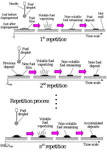
Figure 2-2 Repetition process of deposit formation on a hot surface 46
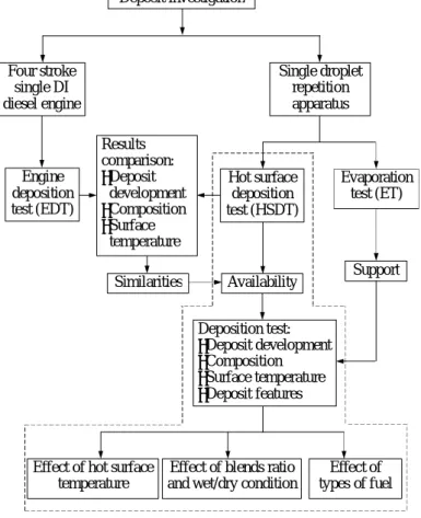
Figure 2-3 General method of deposit investigation 47
Figure 2-4 Photograph of hot surface deposition test bench 49
Figure 2-5 Schematic diagram of single droplet repetition apparatus 49
Figure 2-6 Experiment apparatus of HSDT and hot plate dimensions 50
Figure 2-7 Droplet evaporation for pure and multi-component fuel 51
Figure 2-8 General features of evaporation characteristics 52
Figure 2-9 Temperature correlation 53
Figure 2-10 Deposit surface temperature measurement 54
Figure 2-11 Photograph of the engine deposition test bench 56
Figure 2-12 Schematic diagram of four-stroke single cylinder DI
diesel engine 56
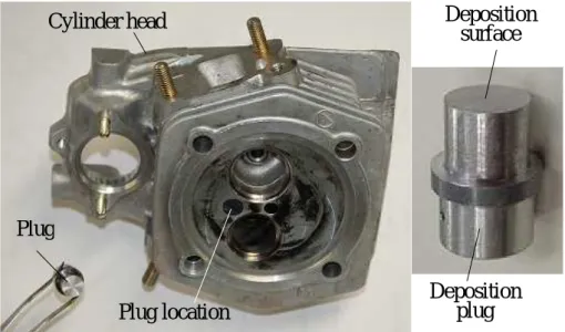
Figure 2-13 Photograph of the deposition plug and its location in the
cylinder head 57
Figure 2-14 EDT using a deposition plug 58
Figure 3-1 Evaporation characteristics for DF, DF+1%L and DF+2%L 63
Figure 3-2 Effect of droplet size on droplet lifetime 64
Figure 3-3 Effect of pressure on droplet lifetime 64
Figure 3-4 Effect of gas temperature on droplet lifetime 64
Figure 3-5 Effect of surface roughness on droplet lifetime 64
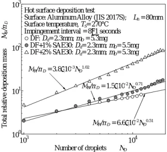
Figure 3-6 Deposit development correlation based on raw data 67
ix
Figure 3-8 Deposit development correlation based on Md 68
Figure 3-9 Deposit development correlation based on mD 69
Figure 3-10 DF and DF blended with SAE30 deposit developments
with number of droplets 70
Figure 3-11 Heat release rate result for DF and DF blended with SAE30 72
Figure 3-12 DF and DF blended with SAE30 deposit developments
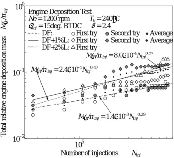
with number of injections 72
Figure 3-13 Absolute mass of deposit composition for HSDT and EDT 74
Figure 3-14 and values comparison 77
Figure 3-15 Percentage of average deposit composition for HSDT and EDT 78
Figure 3-16 Deposit surface temperature for HSDT 79
Figure 3-17 Plug and cylinder head temperatures for EDT 79
Figure 3-18 Surface temperature measurement point for HSDT and EDT 80
Figure 3-19 Droplet interaction behavior on a hot surface 82
Figure 4-1 Dodecane evaporation characteristics 86
Figure 4-2 Diesel fuel evaporation characteristics 87
Figure 4-3 General features of the single and non-single droplet states
during DF evaporation 87
Figure 4-4 Development of DF deposits at various surface temperatures 89
Figure 4-5 Diagram of general deposit tendencies 92
Figure 4-6 Photo-picture of diesel fuel deposits at ND=1,000 and ND=9,000
for single-stage deposit development 93
Figure 4-7 Photo-picture of diesel fuel deposits at ND=1,000 and ND=9,000
for two-stage deposit development 94
Figure 4-8 Comparison of and values for DF deposit development
at various sub-cooled temperatures 96
Figure 4-9 Surface features of deposits at TS = 367 C with ND = 19,000 97
Figure 4-10 Deposit surface temperature fluctuations and droplet lifetime
estimations 98
Figure 4-11 Vaporization conditions during deposit development 100
Figure 4-12 Non-overlapping and dry deposit conditions 100
Figure 4-13 Overlapping and wet deposit conditions 101
Figure 4-14 Wet/dry conditions 102
Figure 5-1 Evaporation characteristics for DF, B100 and
bio-blended diesel fuels 105
Figure 5-2 Deposit developments at imp=5sec 108
x
Figure 5-4 DF deposit development at different temperatures
and impingement intervals 110
Figure 5-5 Photo-picture of B100 and Bio-blended diesel fuel deposits at
ND=3,000 and ND=8,000 with imp=5sec 113
Figure 5-6 Photo-picture of B100 and Bio-blended diesel fuel deposits at
ND=3,000 and ND=8,000 with imp=8sec 114
Figure 5-7 Photo-picture of DF deposits at ND=3,000 and ND=8,000 115
Figure 5-8 B100 and DF deposit surface temperature fluctuations
and droplet lifetime estimations 116
Figure 5-9 Deposit surface temperature comparison for B100
and its blends for imp=5sec and 8sec 118
Figure 6-1 DF and DFP evaporation characteristics 121
Figure 6-2 B100 and B100C evaporation characteristics 121
Figure 6-3 General features for single and non-single droplet states
during diesel and bio-diesel fuel droplet evaporation 122
Figure 6-4 Development of DF and DFP deposits 124
Figure 6-5 Development of B100 and B100C deposits 125
Figure 6-6 Photograph of diesel fuel deposits at ND=1,000 and ND=9,000 127
Figure 6-7 Photograph of bio-diesel fuel deposits at ND=1,000 and ND=9,000 128
Figure 6-8 Comparison of and values for diesel fuels and
bio-diesel fuels at TS=352 C and TS=308 C 129
Figure 6-9 Absolute deposit composition masses 130
Figure 6-10 B100C deposit surface temperature fluctuation at TS=352 C 132
Figure 6-11 B100C deposit surface temperature fluctuation at TS=308 C 133
Figure 6-12 DFP deposit surface temperature fluctuation 133
List of tables
Table 1-1 Problems and causes in using bio-diesel fuel (BDF) 2
Table 1-2 Deposits formed on pistons for various diesel engines 19
Table 2-1 HSDT conditions 54
Table 2-2 Engine specifications 55
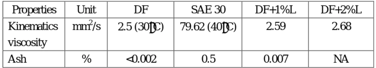
Table 2-3 Properties of tested fuels 59
xi
Table 2-5 Mass fractions of FAME for PME and CME 60
Table 2-6 Properties of SAE 30 and DF blend with lubricant oil 61
Table 3-1 Coefficients of correlation 67
Table 4-1 MEP and HSDT conditions for tested fuels 88
Table 4-2 and values for different surface temperatures 91
Table 5-1 MEP and HSDT conditions for DF, B100 and bio-blended fuels 106
Table 5-2 Logarithmic expression values 111
Table 6-1 MEP and HSDT conditions for diesel fuels and bio-diesel fuels 123
List of abbreviations
Al Aluminum
A/F Air/Fuel
ATDC After top dead center
ave Average
B5 JIS No. 2 diesel fuel blend with 5%wt B100
B20 JIS No. 2 diesel fuel blend with 20%wt B100
B50 JIS No. 2 diesel fuel blend with 50%wt B100
B100 100% Palm oil methyl ester (PME) based bio-diesel fuel B100C 100% Coconut oil methyl ester (CME) based bio-diesel fuel
BDF Bio-diesel fuel
BMEP Brake mean effective pressure
BSFC Brake specific fuel consumption
BTDC Before top dead center
C Carbon
Ca Calcium
CA Crank angle
CME Coconut oil methyl ester
CN Cetane number
CO Carbon monoxide
CR Compression ratio
Cu Copper
CCD Combustion chamber deposit
CPO Crude palm oil
xii
DI Direct injection
DO Dodecane: C12H26
DFP Philippine National Standard diesel fuel
DIRoxidation Differential infrared of oxidation (Degree of oxidation) DF+1%L JIS No. 2 diesel fuel blend with 1%wt lubricant oil (SAE 30) DF+2%L JIS No. 2 diesel fuel blend with 2%wt lubricant oil (SAE 30)
ET Evaporation test
EDT Engine deposition test
EGR Exhaust gas circulation
FAME Fatty acid methyl esters
Fe Ferrum
FBP Final boiling point
H Hydrogen
HC Hydrocarbon
H/C Hydrogen/Carbon
HCCI Homogeneous charge compression ignition
HSDT Hot surface deposition test
IBP Initial boiling point
IDI Indirect injection
LHV Low heating value
Mg Magnesium
MEP Maximum evaporation rate point
MEXA Particulate analyzer: HORIBA, MEXA-1370PM
NOX Oxides of nitrogen
OD Typical diesel fuel
ORI Octane requirement increase
OHV Overhead valve
Pb Lead
PBA Polybutane amine-based additive
PEA Polyether amine-based additive
PM Particulate matter
PME Palm oil methyl ester
PNS Philippine National Standard
R Radical
RME Rapeseed methyl ester
SI Spark ignition
xiii
SOF Soluble organic fraction
Swe Mk1 Swedish class 1 diesel
TDC Top dead center
THC Total hydrocarbon
ULSD Ultra low sulphur diesel
Zn Zinc
Nomenclature
A Constant [-] B Constant [-] a Constant [-] b Constant [-] Dd Diameter of a droplet [mm]Do Initial droplet diameter (in literature) [mm]
do Initial droplet diameter (in literature) [mm]
d dQ
Heat release rate [J/deg.]
Lh Needle tip to the center of hot plate distance [mm]
MR Total deposits on a hot surface [g]
M’R Total deposits on the plug [g]
minj Mass of a single shot injection fuel [g/injection]
MD Total mass of fuel droplets [g]
Md Accumulated mass of fuel droplets [g]
mD Mass of a single fuel droplet [g]
mDep Deposit mass (in literature) [kg]
Ninj Number of injections [-]
ND Number of droplets impinged [-]
Ne Engine speed [rpm]
nrev Engine revolutions [rpm]
nrev Engine speed (in literature) [min-1]
pCh Charge air pressure (in literature) [MPa]
pex Exhaust gas pressure (in literature) [MPa]
pme Mean effective pressure (in literature) [MPa]
xiv
_
q Instantaneous heat flux (in literature) [W/m2]
Rz Roughness of the hot surface (in literature) [ m]
r Coefficient of correlation [-]
Th Heater temperature [ C]
TMEP MEP temperature [ C]
Ti Indicated temperature [ C]
TS Surface temperature [ C]
Td Surface temperature of deposits [ C]
TP Plug temperature [ C]
Tc Cylinder head temperature [ C]
tc Ceiling temperature of the test chamber (in literature) [ C]
Tdeposit Surface temperature of deposit [ C]
tR Running time [hour]
TWall Surface temperature of clean wall [ C]
TW Wall temperature (in literature) [ C]
tw Surface temperature at center of the hot surface (in literature)[ C]
T90 90% distillation temperature [ C]
TSUB Sub-cooled temperature (TS-TMEP) [ C]
W Deposit mass (in literature) [mg]
X Percentage of DF in blended fuel [%]
z Vertical distance from the hot surface (in literature) [mm]
Greek letters
Constant for initial deposition [-]
Exponential index for deposition development [-]
m Surface tension (in literature) [mN/m]
Excess air-fuel ratio [-]
Crank angle [deg.]
inj Injection timing [deg.]
fuel Density of fuel [kgm-3]
m Density (in literature) [g/mL]
life Droplet lifetime [sec]
xv
imp Impingement interval [sec]
p Piston temperature (in literature) [ C] m Kinematics viscosity (in literature) [cSt] Blend Kinematics viscosity of DF blend with SAE30 lubricant [mm2/s]
xvi
Abstract
Deposit formation in the combustion chamber of an engine is a complex phenomenon that causes various engine problems such as reduced engine performance, increased emissions and causes engine damage for diesel engines. The utilization of bio-diesel fuel further increases the tendencies of deposit formation in the engine due to its higher viscosity and distillation temperature compared to diesel fuel. The aim of this study is to clarify fuel deposition in an engine using a simplified method which is referred to as the hot surface deposition test (HSDT). The HSDT is also used to simulate and investigate deposit formations for diesel fuels and bio-diesel fuels on the wall in the combustion chamber instead of using the engine deposition test (EDT). HSDT and EDT showed that both have similar tendencies in deposit development and soot fraction in deposits. HSDT is considered as an initial research step in developing a simplified method for engine deposit investigation and it is capable of differentiating the deposit development among various types of fuels. The deposit development on a hot surface depended on the droplet impingement interval, hot surface temperature, types of fuel, deposit properties, initial stage of deposition, overlapping conditions and competition phenomena during deposit formation, such as a cooling effect, heat transfer effect and chemical reaction effect. These factors determine the existence of wet conditions and the amount of deposits accumulated. Different hot surface temperatures showed different droplet-surface interactions, evaporation lifetimes and wet/dry conditions where various deposit development features resulted. Palm oil methyl ester (PME) which is refer to as 100% palm oil methyl ester based bio-diesel fuel (B100) and its blends (B50, B20 and B5) produced a higher development rate of deposits compared to diesel fuel (DF). Less amount of DF deposits was obtained due to an absence of bio-diesel fuel components, and non-overlapping and dry deposit conditions. Philippine National Standard diesel fuel (DFP) having 1% coconut oil methyl ester (CME) in composition, showed a greater deposit development rate compared to DF, which resulted in a relatively large amount of deposits for DFP. However, for bio-diesel fuels, coconut oil methyl ester (CME) which is referred to as 100% coconut oil methyl ester based bio-diesel fuel (B100C) obtained a slower deposit development rate compared to B100, although the test conditions were changed. Due to the lower value of maximum evaporation rate point (MEP) and shorter droplet lifetime before MEP, utilization of B100C had a greater potential in reducing deposit formation compared to B100.
1
Chapter 1
Engine deposit research: A review of the current literature
1.1 Introduction
For many years diesel engines have been commonly used in transportation due to their advantages over gasoline engines such as high power/weight ratio, high thermal efficiency, simple mechanisms, rigid structure, low breakdown rate and high fuel economy. Their higher efficiency allows less fuel to be used for the same distance. This low fuel consumption is the main reason for the popularity of diesel engines. However, the pollutants emitted from diesel engines during combustion have been considered the major air pollution source throughout the world. Instead of environment pollution, another problem involved with diesel fuels is the increasing price of oil. The phenomenon gives a major impact on world-wide economic development.
Oil price and air pollution are now becoming two of the main driving forces of new energy development. Many researchers have been trying to develop new types of fuel in order to solve problems involved with diesel fuel. Some of them emphasize the potential of palm oil ester, referred to as bio-diesel fuels considered as substitutes for diesel fuels. This can be achieved by forming methyl (or ethyl) esters of palm oils and by using these esters as fuels. Since the viscosity and volatility of these esters, referred to as bio-fuels, are comparable to those of diesel fuel, they can be used for direct injection (DI) diesel engines without modification [1].
Masjuki, et. al. [2] used palm-oil methyl ester and its blends with conventional diesel fuel in an automobile diesel engine and found that the engine performances obtained were comparable with diesel fuel. Bio-diesel fuel and its blends are also capable of reducing emissions. Moreover, the cetane rating, which is a measure of the quality of ignition, obtained with palm oil methyl ester was higher than that of commercial diesel fuel. Although bio-diesel fuels have advantages in reducing emissions and their blends with diesel fuel showed comparable engine performance, their properties and combustion behaviors in an engine have not been well understood. Bio-diesel fuel usage in engines also causes various problems as mentioned by Senda, et. al. [3] in Table 1-1.
2
Table 1-1 Problems and causes in using bio-diesel fuel (BDF) [3]
Problems using BDF Causes
Deterioration of cold start Poor low-temperature fluidity Exhaust of smoke at cold start Exhaust of unburned elements Deposits in combustion
chamber
Incomplete combustion of high boiling components
Plugging of fuel filter Deposit of glycerin and alkali catalysts in fuel
Degradation of fuel Auto-oxidation of fuel
Degradation of rubber product Auto-oxidation of fuel, Swelling of rubber by oxygen
To expand the utility of bio-diesel fuel, many studies on the properties and combustion behaviors of bio-diesel fuels are still needed. One of the important studies for the utilization of bio-diesel fuel is basic research on depositions in engines. Since the deposits in an engine cause surface heat transfer alteration [4, 5], engine knock [6], hydrocarbon emissions [7, 8], and reduce engine lifespan, deposits resulting from bio-diesel fuel should be calculated and countermeasures for its reduction should be developed to ensure the long term use of the engine.
Furthermore, different types of bio-diesel fuels have different properties and show different combustion behaviors. In terms of properties, bio-diesel fuels have less thermal stability, higher values of density and viscosity compared to typical diesel fuel, thus those fuel characteristics increase the possibility of increasing deposit formation in engines.
In this chapter, various aspects of engine deposit available in the current literature is discussed in order to understand the effects and factors of deposit formation in engines. Understanding deposit mechanisms is crucial for finding effective deposit prevention measures. The information and knowledge obtained from the literature can help to enhance our understanding in deposit formation and the deposit development of bio-diesel fuels in this study.
1.2 Bio-diesel fuel
Bio-diesel fuel is defined as fatty acid methyl ester (FAME), which is the result of the reaction of fatty acids with methyl alcohol [9] through a process called transesterification. Figure 1-1 illustrates the transesterification process and the chain structure of fatty acid methyl ester [10]. This type of fuel may be substituted for diesel fuel in engines. Nowadays, bio-diesel fuel has been
3
gaining attention as an alternative for diesel fuel. Diesel engines that use bio-diesel fuel reduce green house gas emission and save fossil fuel. However at this moment, only 5% and 20% bio-blended diesel fuels are practical for use in vehicles. In terms of its properties, compared to typical diesel fuel, it still has higher viscosity and higher distillation properties that can lead to the formation of carbon deposits in the combustion chamber, which has a negative effect on engine performance.
Figure 1-1 Transesterification of fatty acids and typical chain structure of fatty acid methyl esters [10]
Bio-diesel fuels have a high and narrow distillation range [11] and the final boiling point (FBP) is identical to diesel fuel in some cases [12]. The bio-diesel fuel distillation properties are shown in Figure 1-2. The high and narrow range of distillation properties caused the bio-diesel fuel is easy to condense and forms liquid film on the wall surface in the combustion chamber. The formation of liquid film increases the tendencies to form deposits on the wall. As mentioned by Zheng, et. al. [12], the low volatility and high viscosity of bio-diesel fuels may result in poor fuel atomization and air/fuel mixing due to the formation of the larger size of fuel droplets during fuel atomization in engines. Furthermore, different types of bio-diesel fuels have different properties and combustion behaviors. For example, palm oil methyl ester (PME) and coconut oil methyl ester (CME) bio-diesel fuels, both have different properties and combustion behaviors. According to Ejim, et. al. [13], PME has a higher value of viscosity and surface tension compared to CME. Hence, during engine operation, spray vaporization for PME and CME are different due to the bigger size of PME droplets formed compared to CME. One of the parameters that is effected due to bigger size of fuel droplets is the ignition delay during the combustion process. The ignition delay will increase for PME compared to CME, where its droplets
C O C O R1 C O C O R2 C O C O R3 H H H H H 3CH3OH + C OH C OH C OH H H H H H + C O C O 3Rn H H H
Triglyceride Methanol Glycerol
3 Fatty acid methyl esters (Bio-diesel fuel) KOH Catalyst Rn: Unsaturated acid
4 require more time to vaporize.
Figure 1-2 Distillation profiles for diesel and bio-diesel fuels [12]
Distillation properties, particulate formation propensity and the value of viscosity for bio-diesel fuel are the factors that effect the deposit formation. However, the distillation property is the most dominant property that determines the amount of deposit for different types of fuels.
Kalam, et. al. [5] also mentioned that the used of palm oil bio-diesel fuel in diesel engines faced some degree of difficulty such as incomplete combustion, including piston ring sticking and carbon deposits caused by the high viscosity and density of fuel plugging the injector jets, which in turn caused poor injection, fuel atomization and vaporization.
Konno, et. al. [11] investigated carbon-deposit formation characteristics and the formation factors of diesel engines fueled with rapeseed methyl ester (RME) and found that the carbon deposit of RME accumulates rapidly, and has a long term periodic break-off compared to diesel fuel as shown in Figure 1-3.
The physical and chemical properties of bio-diesel fuel influence the characteristics in the engine’s combustion chamber. In terms of bio-diesel fuel’s influence on injection characteristics, Yamane, et. al. [10] found that the utilization of bio-diesel fuel shortens spray penetration compared to diesel fuel. Thus, the air-fuel mixing process was relatively poor for the bio-diesel fuels. The result obtained by Yamane, et. al. [10] was for non-evaporated spray. Bio-diesel spray penetration is different for evaporated spray as shown by the study conducted by Senda, et. al. [3]. In this study, greater spray penetration was obtained compared to diesel fuel. This is due to higher density and also a longer time for evaporation
5
for bio-diesel fuel compared to diesel fuel, which resulted in a greater momentum of fuel spray to axial direction. Although both Yamane, et. al. [10] and Senda, et. al. [3] used almost similar properties of recycled cooking oil methyl ester bio-diesel fuel, their different test environment gave different results of spray penetration for bio-diesel fuel compared to typical diesel fuel.
Figure 1-3 Relation between wall temperature TW and maximum and minimum
weights of deposit [11]
The properties of different types of bio-diesel fuel are different from typical diesel fuel that cause different combustion behavior for bio-diesel fuels. To reduce the differences, a small amount of bio-diesel fuel (less than 20%) can be blended with diesel fuel in order to obtain behavior similar to diesel fuels. Rakopoulus, et. al. [14] mentioned that by blending 10% and 20% bio-diesel fuel with neat diesel fuel, the injection rate or the macroscopic behavior of the spray is almost identical to neat diesel fuel for the same engine operating conditions (injection timing, speed and load). This study also showed that all 10% and 20% of various bases of bio-diesel fuels blended with diesel fuel obtained higher amounts of HC emission compare to diesel fuel during medium load of engine operation. Although at high load engine operation, the tendencies of the bio-blended diesel fuels to emit HC were similar to diesel fuel, some of the bio-blended diesel fuels still obtained more HC emission as shown in Figure 1-4. HC emission is related to incomplete combustion process resulting in unburned hydrocarbons. Thus, the increases of HC emission for these bio-blended diesel fuels also show the tendencies of the fuel to form more deposits in the engine.
Sinha, et. al. [15] investigated the effects of different blends of rice-bran oil methyl ester (10% and 20%) to combustion in engines. In the study, cumulative
6
heat release for bio-diesel blends decreases as the proportion of bio-diesel is increased in the blend, owing to the lower heating value of bio-diesel fuel. Further, Sinha, et. al. [15] mentioned that more fuel is required in the case of bio-diesel blends because the calorific value of these blends is lower than that of diesel and caused longer combustion duration for bio-diesel blends.
Figure 1-4 Emitted total unburned hydrocarbons (HC) for diesel fuel, bio-blended diesel fuels and vegetable oil blends of various origins for medium load (a) and
high load operation (b) [14]
1.3 Engine deposits
Deposits or carbon deposits may be defined as heterogeneous mixtures made up of carbon residue (ash), carbonaceous mixtures (soot) and oxygenated resinous organic material that bind together as mixtures [16]. It can also include any number of materials, excess, or residue that is gradually grown or accumulated on critical parts of an internal combustion engine [17]. Engine parts in the combustion chamber such as the cylinder head, piston, intake and exhaust valves, and injector tip are common parts where engine deposits regularly accumulate, as shown in Figure 1-5.
Deposits on the various parts of an engine cause substantial impact on engine performance, fuel economy, cold-start, warm-up drivability, and exhaust emission
7
through various problems such as lowering the fueling rate, restricting air flow, increasing compression ratio, altering spray pattern, inducing knock, degrading thermal conductivity, and reducing catalyst reactivity [18]. Further, a new field problem associated with flakes of combustion chamber deposit getting trapped on the exhaust valve seat has been reported by Kalghatgi [19]. The deposit flakes cause difficulties in start-up and poor driveability, increase in hydrocarbon emissions and rough running [20, 21], and eventually, will cause a loss of compression in the cylinder.
Figure 1-5 Deposits on various parts of the combustion chamber
In terms of engine damage, deposits caused wear and fouling of engine parts, especially on piston and cylinder surfaces as mentioned by Muzikus, et. al. [22] and Artemiev [23]. Piston deposits can cause ring sticking and scuffing which interferes with the normal operation of an engine [24]. Eilts [25] mentioned that deposit formation in the engine causes serious damage in direct injection diesel engines during long low load operation. In modern engine design, deposit formation in the engine increases unburned HC due to adsorption and desorption of HC by the deposits. NOx emissions also increase due to the insulation effect and heat storage of the deposits that increase the gas temperature in the combustion chamber. In advanced engine technology systems such as injection systems that have small injector holes with high injection pressure, deposit formation is more significant. Even small amounts of deposits can disturb the system’s performance. Intake valve Exhaust valve Injector Cylinder Cylinder head Piston Piston ring Deposit layer
8 1.3.1 Deposit origin
In general, the main contributor of combustion chamber deposits may derive from fuel, lubricant oil or from a combination of both. However, the domination of fuel and lubricant oil in contributing deposits depend on various factors such as engine type and engine parts location in the combustion chamber. As mentioned by Lepperhoff, et. al. [26], deposit locations at high temperature areas of an engine primarily result from nonmetallic residuals from evaporating or burning fuel and/or lubricants.
Different studies suggest different levels of domination of fuel and lubricant oil in deposits. Some studies found that lubricant oil is the primary contributor of combustion chamber deposits (CCD) [7, 27-29]. The presence of lubricant oil components and elements such as ash residues, fractions of inorganic materials, and high boiling point hydrocarbons found in the studies proved the involvement of lubricant oil in deposit formation.
Fukui, et. al. [29] investigated the influence of fuel and lubricant oil on the CCD weight in a single cylinder two-stroke SI engine, where the engine’s test was operated with gasoline and i-octane as fuel and oil A and B as lubricant oil. The result in Figure 1-6 shows that the influence of lubricant oil on CCD accumulation in the engine was found to be larger than that of unsaturated hydrocarbon included in fuel. Diaby, et. al. [30] conducted an investigation on first ring groove deposits in a four-cylinder diesel engine. The deposit at the first ring grooves in the study were analyzed for their chemical components by using X-ray dispersive energy equipment, which found no elements that could be related to fuel components. Thus, the study has shown that the deposits of the first ring grooves of the investigated diesel engine are mainly carbonaceous and result principally from the lubricant degradation, where a large proportion of metallic elements were found from the analysis. It appeared that the degradative oxidation of the lubricant induces polymerization reactions, leading to the formation of a varnish acting as a binder which can ensure cohesion between carbon particles and metallic particles of wear, worsening the cycle of lubricant degradation. In another study [31], the soot produced from diffusion burning of the diesel fuel was found to contribute only 20% to deposits, the remainder being lubricating oil-derived.
In some types of diesel engines, the engines are lubricated by the diesel fuel itself, so the lubricant is no longer a source for metal ions in deposits in the engine [27]. Diesel fuel today contains a variety of acidic components such as fatty
9
acids, with different degrees of un-saturation that are commonly used as lubricity additives in diesel fuel. Such acids have been shown to readily react with metal ion impurities in the fuel to form metal soaps. As mentioned by Ullmann, et. al. [27], these metal soaps have been associated with the formation of nozzle tip/ spray-hole deposits.
Figure 1-6 Influence of fuel and lubricant oil on CCD formation [29]
Previous research conducted by Ra, et. al. [32] has focused on soot formation and deposition on the cylinder wall (piston bowl and top surface, cylinder head and parts of the cylinder liner exposed to combustion gases) that originate from the injected fuel. In the research, the effect of piston ring pack crevice flow and lubricant oil vaporization on heavy-duty diesel engine was investigated numerically, where various models such as combustion, soot formation, deposition and oil vaporization models were used. However, a substantial amount of soot deposition is found in crevice regions, including the piston ring pack, which indicates that crevice-borne hydrocarbon fuels may play an important role in deposit formation on piston/crevice surfaces. Devlin, et. al. [24] investigated deposits on a Sequence IIIG piston. The result showed that the deposit formed on the piston top and on the second land of the piston was fuel-derived. The contribution of lubricant in the deposit composition was less than 17%.
In terms of fuel’s effect on injector deposits in diesel engines, Leedham, et. al. [33] suggested that trace amounts of metals could be implicated in the deposit formation mechanism. The engine testing carried out in the study showed that base fuel did not have significant levels of deposits. However, in the presence of trace amounts of zinc, a substantial level of deposits is generated. The lubricity additives may play a role in the uptake of zinc into the fuel. The ester lubricity additives do not affect the zinc levels of the fuel, whilst the acid lubricity agent appeared to be implicated in the uptake of the zinc as shown in Figure 1-7. The figure shows the effect of various lubricity additives in two different fuels, which
10
are Swedish Class 1 Diesel (Swe Mk1) and Ultra Low Sulphur Diesel (ULSD). It appeared that lead (Pb) as well as zinc (Zn) was susceptible to absorption into the fuel, whilst the other metals were not detected. The results confirmed the earlier studies; the ester lubricity agents were not picking up metals, whilst the acid technology was consistently picking up lead and zinc into the fuel.
Further, in terms of fuel contribution to deposit formation, Ebert [34] noted that unburned fuel, in combination with crankcase oil, oxidized and condensed, producing varnish and sludge. Another study conduct by Cloud, et. al. [35] suggested that sulphur is converted to sulphur trioxide which in turn attacks the lubricating oil producing sludge and eventually varnish-type deposits. Thus, from this evidence, there are many factors involved in fuel and lubricant domination in combustion chamber deposits.
Figure 1-7 Zinc uptake by lubricity additives in two fuels [33] 1.3.2 Deposit characteristics
(1) Deposit structure
The structure of engine deposits is sensitive to many parameters, including base fuel composition, engine operating temperatures, and the presence of deposit control additives in the fuel [36]. Physical features of deposits contribute to various effects in the combustion chamber such as heat transfer alteration and HC source. The porous structures of deposits activate the fuel storage mechanism and play an important role on the HC level [18]. Furthermore, deposit masses were found to correlate well with HC emissions as mentioned in theoretical work done by Eilts [25].
11
Guralp, et. al. [17] investigated properties of the deposits layer, since it is the combustion chamber deposit coating that affects heat transfer and combustion. The porous volumes found in the deposit material presented the potential for intra-material heat transfer through convection and radiation. Given that the chemical structure of deposits varies over time and is influenced by engine operating systems, it was anticipated that the conductivity of deposits would also vary [36].
Additionally, according to Zerda, et. al. [37], a deposit’s internal microstructure may directly relate to its intractability and ease of removal. A more graphitic and condensed microstructure may be more impervious to oxidation and burn-off, and consequently more difficult to remove from the engine.
(1-1) Wall temperature effect
Depending on the temperature level at the location where deposits are formed, deposits will have different structures. Nagao, et. al. [38] stated that the deposit changes in quality according to the wall temperature. In the study, Nagao, et. al. [38] mentioned that at a high level of wall temperature (>550 C), the deposits are very thin, soft, dry and so removable that the gas flow existing in the combustion chamber can blow them off. In terms of quality, the deposits are mostly carbon. However, at a lower level temperature (<200 C), the deposits adhere to the wall and are moistened owing to the fuel. The deposits consist of fuel, adhesive and carbon.
Similarly with Lepperhoff, et. al. [26], the effect of different temperature ranges on deposit structures was described. However, the range of high level temperature was lower than that discussed by Nagao, et. al. [38]. At high temperature levels (>300 C) according to Lepperhoff, et. al. [26], different light deposit colors are visible. A very thin deposit layer is typical for this temperature range. However, at low temperature levels (<200 C), dark materials including black carbon, wet hydrocarbons and soot were observed in the study.
(1-2) Location of deposits
Zerda, et. al. [37] proved that the morphology of the deposits varies with their location inside the combustion chamber. The surface area and the total pore volume depend on the location of the deposit, whether removed from the cylinder head, the piston top, or the intake valve as shown in Figure 1-8.
12
The structure of the deposits removed from the combustion chamber’s cylinder heads is more porous than that of piston top deposits. Likewise, intake valve deposits were seen to be less porous than combustion chamber deposits. Pore size distribution of deposits for the cylinder head is the largest, followed by piston top and intake valve deposits.
Figure 1-8 Comparison of pore size distribution of deposits generated by fuel without additives on different parts of an engine [37]
(1-3) Fuel component effect on deposit structure
Zerda, et. al. [37] also investigates the effect of additives on deposit structure and found that the additives change the distribution of pores in the deposits as shown in Figure 1-9. In the figure, additive concentrations for PEA-1 (polyether amine-based) and PBA-1 (polybutane amine-based) are the same. The study also found that increased concentration of additives results in reduced surface areas. This effect is accompanied by a small increase of the deposit mass. It is likely that the additives or their fragments are incorporated into the deposits by filling up and blocking access to some of the cavities. The surface area of the deposits decreases with increased concentration of the additives.
On the other hand, the study of carbonaceous deposits conducted by Zerda, et. al. [8] and Edwards, et. al. [39] concluded that fuels with higher aromatic contents yield more condensed deposits. Zerda, et. al. [8] add in the study that the fuel aromaticity increases the deposit structure which becomes more graphitic.
Cylinder head Piston top Intake valve
13
Figure 1-9 Comparison of pore size distribution of deposits generated by fuel with different additives at the same concentration [37]
(1-4) Deposit structure at different layers
Two distinct CCD morphologies were identified in a previous study when deposits were exposed to higher temperatures [7, 28, 40] as shown in Figure 1-10.
Figure 1-10 Deposit layers [40]
The first layer is the lower layer closer to the metal surface in which condensation of highly volatile compounds from fuel and oil takes place. The deposit in this layer has a “lacquer-type” structure and is very difficult to remove. This layer was also found to have a higher aliphatic portion than subsequent higher layers which were characterized by a coal-like structure. The deposits in this layer are more homogenous and maintain their cohesiveness.
The second layer which refers to the upper layer is composed of molecules with less bonding tendencies and which can be more easily removed. This layer is carbonaceous in character and has a soot-like chemical structure. In this layer, deposits were found to have an aromatic content similar to soot. In this deposit layer, more loose particles of different shapes with dull edges were also present. They were more disperse in structure and covered with very viscous liquid or
Cylinder wall
Upper layer Lower layer
Base fuel Base fuel + PEA-1 Base fuel + PBA-1
14 polymer.
(2) Deposit properties
The internal porosity of combustion chamber deposits may determine thermal conductivity, thermal diffusivity, and heat capacity, leading to the thermal insulation of the metal parts and heat storage [37].
Jonkers, et. al. [28] used a deposit conductivity probe installed in the cylinder head of a DI diesel engine to investigate deposit conductivity in a real engine. The study found that as deposit formation progressed, the deposit conductivity decreased as shown by the conductivity probe voltage drop in Figure 1-11. This was probably caused by an increase in the concentration of aliphatic groups and a decrease in polyaromatics in carbon black that led to the decrease of deposit conductivity. Soot is considered to be of a polyaromatic (graphitic) structure and thus highly conductive. Increased conductivity was observed during the initial start-up of the engine, possibly caused by the presence of aromatics. Thereafter, it is likely that aliphatic components from the oil contributed most to deposit formation as conductivity decreased. The probe voltage-drop profile changed around cylinder peak pressure with an inflection in the curve. It is believed that this change is also indicative of a change in deposit structure.
Figure 1-11 Conductivity probe voltage drop for accelerated deposits [28]
Results of thermal diffusivity obtained from Guralp, et. al. [17] in Figure 1-12 was calculated by using the relationship between local peak temperature phasing and combustion chamber deposit thickness combined with the formula of thermal
Increased time
15
diffusivity. The result demonstrated a strong correlation between deposit thickness and the diffusivity of the combustion chamber deposit layer at two different locations of cylinder head surfaces for a homogenous charge compression ignition (HCCI) engine. Thicker layers of material have a lower effective thermal diffusivity. This is due to the fact that, as the deposit is forming, its morphology is constantly changing as well. The degree of porosity, the consistency, and the types of HC molecules that make up different layers of the total material are constantly changing.
Nishiwaki, et. al. [41] determined the thermal conductivity and diffusivity of deposits in SI and diesel engines based on one-dimensional unsteady conduction in a solid having constant thermal properties. For both engines, thermal conductivity was influenced by engine load. Additionally, for the SI engine, the properties were also influenced by the equivalence ratio and engine speed. In terms of thermal diffusivity, SI engine deposits also depend on the equivalence ratio, engine load and engine speed. However, for the diesel engine in the study, no clear factors effecting thermal diffusivity were determined.
Figure 1-12 Plot of calculated effective thermal diffusivity as a function of CCD thickness at each heat flux probe location in the cylinder head [17]
Anderson, et. al. [42] claimed that the effective porosity of the material is a dominant characteristic which controls the rates of heat transfer at the surface, suggesting that conduction is indeed the major mode of heat transfer related to deposits. Tree, et. al. [43] extended this line of reasoning by claiming that the porous characteristics of the combustion chamber deposit layer actually interacted with fuel spray in a diesel engine, causing an increase in the duration of heat
16
release [17]. Additionally, Woschni [44] suggested that the thermal storage capacity of deposits on the wall will cause the flame to burn closer to the present thermal boundary layer and actually increase the heat transfer to the wall.
1.3.3 Deposit mechanisms
Knowledge of how deposits are formed and what the influencing parameters are can be used to describe any deposit formation at different locations in engine’s combustion chambers. Furthermore, when the fundamental mechanisms of deposit formation in engine’s combustion chambers are clearly understood, engine deposits can be predicted which will help to improve engine durability.
Lepperhoff, et. al. [26] suggested the physical mechanisms of deposit which included the formation and removal mechanisms as illustrated in Figures 1-13 (A) and 1-13(B), respectively.
Figure 1-13 Deposit formation and removal mechanisms [26]
(1) Formation mechanisms
The mechanisms of deposit formation are described as a function of time and these mechanisms are influenced by physical conditions at the location of deposit formation such as temperatures, temperature gradients, conditions of flow concentrations and concentration gradients of depositable components. The depositable component can be divided into different groups: 1) Gaseous and high molecular liquid substances which follow the flow of the gas itself; and 2) particles
(A) Deposit formation
Oxidation Evaporation Desorption Abrasion Break off Wall Deposit layer (Soot, HC) (Volatile fraction) (Gaseous components) (Compl. Deposits) (Porous deposits) Wash off (B) Deposit removal Sticking / Incorporation/ Impaction particles 0 T im e sc a le In d u c ti o n p h a se D e p o si t g ro w th Thin film Condensation of gaseous component Adsorption of gaseous components Reaction of the hydrocarbons Compression of the layer Wall
17 which cannot follow the gas flow direction.
(1-1) Liquid film formation
Liquid film formation can be caused by the condensation of heavy gaseous components [26] and fuel impingement on the wall surface. The reactivity and the evaporation behavior of the liquid components on the wall surface result in deposits.
In the case of condensation, this process is mainly influenced by the wall. The temperature gradient near the cooled wall caused thermal diffusion of heavy gaseous components. This effect resulted in an increased concentration of heavy gaseous components near the wall. These gaseous components are high boiling components, mostly hydrocarbons. The gaseous components condense and adsorb at the wall due to low wall temperatures. The deposit formation starts with this condensation of high boiling hydrocarbons at the wall.
Formation of fuel film through fuel impingement also contributes to deposit formation on the wall where the film also acts as a binder to the particles in the combustion chamber. The area directly exposed to spray impingement has high risk of obtaining a great amount of adhered deposits.
(1-2) Sticking/ incorporation/ impaction of particles
The temperature gradient near the cooled wall leads to high thermophoretic forces transporting the particles to the wall. Increasing temperature gradients lead to stronger thermophoresis. This effect causes increased particle concentration near a cold wall. The particles are deposited by sticking, incorporation and impaction. The sticking effect is caused by adhesive forces between the wall and particles. Incorporation is the attachment of the particles in a liquid surface layer. Impaction takes place by the phenomenon of thermophoresis.
No carbon particle can adhere to a dry, non-sticky wall. To build up deposits, a contact medium between the wall surface and particle is necessary. The contact medium is provided during the formation of liquid film on the wall surface. The deposits grow continuously by additional sticking and the incorporation of particles to the layer. With growing deposit thickness, the isolation effect takes place. This leads to an increase in surface temperature and low bonding forces restrict the deposition of more particles.
18 (1-3) Adsorption of gaseous component
The incorporation and impaction of particles probably develops the structure of deposits with high soot portions. The porosity of the deposit plays an important role in the adsorption of gaseous components. Gaseous components diffuse through the porous layer of the deposit and are adsorbed or condense in the layers of lower temperature. This results in an increase in the layer density supported by the pulsation of the gas flow.
(1-4) Reaction of hydrocarbons
Once the deposits are attached to the wall, an additional chemical reaction (oxidation, pyrolysis, dehydration, polymerization, etc) [26, 30] can take place. The chemical reactions are caused by the influence of temperature combined with the long residence time. If the wall temperature is relatively low, fuel accumulated on the wall can evaporate by the heat supplied by the surrounding gas of comparatively high temperature and the residual fuel is left on the surface as a lacquer-like substance [38].
(1-5) Compression of the layer
Compression during engine stroke might affect the deposit formation mechanism. The compression can change the structure of the deposit into a more compact structure. Further, the condition will effect the formation of the next layer. After a number of engine strokes, the deposit substance accumulates and then solidifies into a dry lump which is easily removed by some mechanical causes such as vibration, the impact of spray and drag force due to gas flow [38].
(2) Removal mechanisms
Lepperhoff, et. al. [26] suggested 6 types of removal mechanisms during deposit development in engines. The removal mechanisms are:
1) Oxidation of soot and hydrocarbon due to high gas and deposit temperature. 2) Evaporation of volatile fraction when temperature increases.
3) Desorption of gaseous components mainly caused by temperature increase. 4) Abrasion due to low adhesive force.
19
5) Break off, especially part of the deposit that has porous structure due to shearing stress.
6) Wash off, where flow of liquids brings away the deposit precursor probably having a potential for increasing the amount of deposit.
For these removal mechanisms, there is probably no sequence of mechanisms. The occurrence of each removal mechanism depends on engine operation and the condition in the combustion chamber. Deposited components are removed by physical, mechanical and chemical mechanisms.
Physical mechanisms include evaporation and desorption of volatile and gaseous components as well as mechanical wash off. Evaporation and desorption are initiated by an increase in temperature. For instance, this can happen at the deposit surface by thermal isolation effects of the deposits themselves.
Mechanical mechanisms include the abrasion of complete deposits or parts of them and the breaking off of porous deposits. Abrasion takes place when aerodynamic forces exceed bonding forces. The breaking off effect is initiated by a temperature change resulting in the extension of the wall and deposit layer. These unequal extensions lead to shearing stresses which enable the initiation of the breaking off mechanism.
Chemical mechanisms include the washing off of soluble deposit portions and the oxidized carbon and hydrocarbon deposits. Liquids such as condensate water and fuel wash off soluble deposits. To oxidize carbon and/or hydrocarbon deposits, an oxygen-rich atmosphere, certain temperatures and time are necessary. Oxidation starts at a temperature exceeding approximately 200 C for hydrocarbons and approximately 500 C for carbon. This high temperature can be caused by high gas temperatures or high deposit wall temperatures.
1.3.4 Factors of deposit formation
The formation of engine combustion deposits is a complex phenomenon which depends on various factors such as fuel, oil, additives, mixture preparation, combustion chamber design, wall temperature, gas flow conditions, gas concentration gradient near the wall, etc [17, 18, 26]. However, different engines and operating conditions are believed to result in different deposit formation as shown by the result in Table 1-2 obtained by Sevast’yanov [45] who investigated high-temperature deposits on pistons for different locomotive and marine diesel engines that used different grades of oils.
20
Table 1-2 Deposits formed on pistons for various diesel engines [45] Engine Oil grade
Carbon deposits (g) formed on pistons after running locomotives 100,000 km
Piston head Grooves and land Oil cooling passages
2D100 M-12 0.7 13.0 7.7
2D100 M-12V 10.8 12.5 3.3
10D100 M-14V 12.6 14.6 6.4
11D45 M-14V 15.6 25.4 52.8
11D45 M-14Vts 14.2 24.0 1.5
From previous literature regarding deposit formation in an engine’s combustion chamber, factors such as liquid film formation, wall surface temperature, air/fuel ratio, engine operating conditions, and fuel and lubricant oil were widely investigated.
(1) Liquid film formation
Liquid film formation on wall surfaces in combustion chambers is one of the main causes of deposit formation. The liquid film that acts as a contact medium can be formed by fuel and/or lubricant oil whether through impingement, condensation or liquid flow on various engine parts in a combustion chamber.
Fuel film formation through spray impingement usually occurs in small, high speed engines during the injection period. For engines exposed to this type of fuel film formation, the amount of deposit accumulated and its thickness on the engine part surfaces are closely related to the wall surface temperature and also the fuel impingement area. The wall area that is directly exposed to spray impingement has a high tendency to obtain more deposit formation on the surface. As shown by the deposit conditions on a piston surface for single DI diesel engines in Figure 1-14, Yamada, et. al. [46] proved that the place where the fuel spray was expected to impinge had a greater amount of adhered deposits. As the engine running time increased, the amount of deposit accumulated at the area where the fuel spray impinged also increased.
Due to the high temperature and high pressure environment in a combustion chamber, the high boiling point hydrocarbons from fuel and lubricant oil vaporizes. Depending on the effectiveness of air/fuel mixing during the combustion process, part of these vapors are not burned, and these vapors that are in contact with wall surfaces having relatively lower temperatures condensed and formed liquid film on
21
the wall. Further, this liquid film was involved in various processes contributing to deposit formation. For fuel liquid film, the sources of condensed fuel can be leftover unburned fuel from incomplete combustion and extra fuel mass accumulated from direct injection spray impingement [17]. The boiling point of the fuel was a good indicator for its tendency to result in deposit formation through condensation. Higher boiling point fuels have a greater chance of condensation, leading to greater rates of deposit formation than lower boiling point fuels.
Figure 1-14 Deposit formation on the piston surface after 285 min. after engine start [46]
The intake valve and injector nozzle holes are the common parts of an engine that involve liquid flow. The tendency of deposit precursors to remain on the wall depends on the wall temperature and fuel distillation properties. The deposit precursors disperse in fuel that remains on the wall. After a time, the fuel will evaporate and leaves deposit precursors on the wall. Kinoshita, et. al. [47] investigated the factors of nozzle deposit formation through an injector bench test and engine dynamometer test, and mentioned the significant effect of the distillation temperature of fuel. In the study, it was found that when the wall temperature is lower than T90 distillation temperature of the fuel, where most of the fuel remains in a liquid state, the deposit precursor was wash away by the next fuel flow. Due to the wash off process, less deposit remained on the wall for lower temperatures. However, when the wall temperature is higher than T90,
22
most of fuel evaporates and the deposit precursors cohere to the wall.
The result obtained by Kinoshita, et. al. [47] is shown in Figure 1-15. The reduction of fuel flow rate in the figure is dependent on the formation of deposits in the nozzle holes. More deposit formation caused more reduction of fuel flow rate. Thus, the nozzle temperature close to T90 temperature obtained a greater reduction of fuel flow rate due to more deposit formation. From this evidence, the effect of wall temperature for deposit formation involved in liquid flow was different than the effect of wall temperature on deposit formation through spray impingement and condensation.
Figure 1-15 Relation between nozzle temperature and reduction of fuel flow rate in an injector [47]
Lepperhoff, et. al. [26] investigated the liquid flow effect on deposit formation in a cooled pipe with a diesel exhaust gas stream and used oil as a liquid. At places with a smaller liquid flow, the incorporation of particles causing an increase in viscosity that leads to a slowing down of the liquid flow. Here the liquid went to a sticky layer with the effect of a higher collection and incorporation of particles. The higher the rate of incorporated particles, condensed depositable components and absorbed depositable components, the higher the build up of deposits. A wall covered with liquid with a high liquid flow sufficient to produce a continuous wash off of all particles of deposit, can reduce deposit formation on the wall. These explanations can be applied to deposit formation on the intake valve, on the injector tip and in the injector nozzle. The effect of liquid flow on deposit formation is shown in Figure 1-16.
![Figure 1-8 Comparison of pore size distribution of deposits generated by fuel without additives on different parts of an engine [37]](https://thumb-ap.123doks.com/thumbv2/123deta/6225908.1091027/29.892.280.640.302.556/figure-comparison-distribution-deposits-generated-additives-different-engine.webp)
![Figure 1-14 Deposit formation on the piston surface after 285 min. after engine start [46]](https://thumb-ap.123doks.com/thumbv2/123deta/6225908.1091027/38.892.327.610.363.700/figure-deposit-formation-piston-surface-min-engine-start.webp)
![Figure 1-22 Effect of deposits on instantaneous surface temperature and instantaneous heat flux (1200 rpm, full load) [54]](https://thumb-ap.123doks.com/thumbv2/123deta/6225908.1091027/47.892.207.714.143.470/figure-effect-deposits-instantaneous-surface-temperature-instantaneous-heat.webp)
![Figure 1-26 Variation of compression ratio, charge air pressure and load [25]](https://thumb-ap.123doks.com/thumbv2/123deta/6225908.1091027/52.892.159.754.336.647/figure-variation-compression-ratio-charge-air-pressure-load.webp)