Study on Titanium Dioxide Nanomaterials
for Enhanced Photocatalytic and
Dye-Sensitized Solar Cells Performances
Linfeng Xu
Japan
March 2019
Contents
CHAPTER I
General Introduction ... 1
1.1 Introduction ... 1
1.2 Physicochemical Properties and Crystal Structures of TiO
2... 2
1.2.1 Crystal Structures of TiO
2Polymorphs ... 2
1.2.2 Electronic Band Structure of TiO
2Polymorphs ... 5
1.2.3 Thermodynamic Stability of TiO
2Polymorphs ... 7
1.3 Surface Structures and Surface Energy of TiO
2Polymorphs ... 8
1.3.1 Surface Structures of Stoichiometric TiO
2Polymorphs ... 8
1.3.1.1 Surface Structures of Stoichiometric Anatase TiO
2... 8
1.3.1.2 Surface Structures of Stoichiometric Rutile TiO
2... 9
1.3.1.3 Surface Structures of Stoichiometric Brookite TiO
2... 10
1.3.2 Surface Energies of Crystal Facets of TiO
2Polymorphs ... 11
1.3.3 Surface Energy Effect on Crystal Shape (Wulff Construction)
... 13
1.3.4 Surface Energy Effect on Bandgap (Quantum Size Effect) ... 15
1.3.5 Surface Effect on Chemical Properties ... 17
1.4 Photocatalytic Reaction ... 18
1.4.1 Semiconductors as Photocatalyst ... 18
1.4.2 Semiconductor
Photocatalytic Materials ... 19
1.4.3 Photocatalytic Reaction of TiO
2Polymorphs ... 21
1.4.3.1 Reaction Mechanism of TiO
2Polymorphs ... 21
1.5 Facet Effect on Photocatalytic Reaction of TiO
2Polymorphs ... 25
1.5.1 Synthesis of {101}-Faceted Anatase TiO
2and Photocatalytic
Behavior ... 25
1.5.2 Synthesis of {010}-Faceted Anatase TiO
2and Photocatalytic
Behavior ... 26
1.5.3 Synthesis of {001}-Faceted Anatase TiO
2and Photocatalytic
Behavior ... 28
1.5.4 Synthesis of [111]-Faceted Anatase TiO
2and Photocatalytic
Behavior ... 31
1.5.5 Comparison of Photocatalytic Activity of Anatase with
Different Crystal Facets ... 33
1.5.6 Synergistic Effect of High-Energy Facet and Low-Energy Facet
on Photocatalytic Activity for Anatase... 34
1.5.7 Facet Effect on Rutile TiO
2Photocatalytic Activity ... 35
1.5.8 Facet Effect on Brookite TiO
2Photocatalytic Activity ... 36
1.6 Nanocomposite Effect on TiO
2Photocatalytic Reaction ... 37
1.7 Visible Light Active TiO
2Photocatalyst ... 38
1.8 TiO
2Nanocrystals for Dye Sensitized Solar Cells (DSSCs) and
Perovskite Solar Cells (PSCs) ... 39
1.8.1 Progress on DSSCs and PSCs ... 39
1.8.2 Structures and Operation Principles of DSSCs and PSCs ... 41
1.8.3 Characteristic Parameters of Solar Cells ... 44
1.8.4 Crystal Facet Effect of TiO
2on DSSCs Performances ... 45
1.9.1 Solution Processes for Synthesis of TiO
2Nanocrystals ... 47
1.9.2 Topochemical Process for Synthesis of TiO
2Nanocrystals ... 48
1.9.2.1 Layered Titanate Compounds ... 48
1.9.2.2 Synthesis of TiO
2Nanocrystals from Layered Nanosheets
... 49
1.10 Purpose and Contents of This Research ... 51
1.11 References ... 53
Chapter II
Size-controlled [111]-Faceted Anatase TiO
2Nanocrystals: Facile
Hydrothermal Synthesis Process, Bandgap Blue Shift, Enhanced
Photocatalytic and Dye-sensitized Solar Cell Performances ... 61
2.1 Introduction ... 61
2.2 Experiment Section ... 66
2.2.1 Hydrothermal Synthesis of TiO
2nanocrystals ... 66
2.2.2 Physical Analysis ... 67
2.2.3 Photocatalytic Characterization ... 67
2.2.4 Fabrication of Dye-Sensitized Solar Cells and Photovoltaic
Characterization ... 68
2.3. Results and discussion ... 69
2.3.1 Synthesis of TiO
2nanocrystals from TTIP-TMA solution ... 69
2.3.2 Formation mechanism of [111]-faceted anatase nanocrystals 75
2.3.3 Effect of crystal facet on photocatalytic activity and electronic
band structure ... 84
2.4. Conclusions ... 95
2.5 References ... 95
Chapter III
Polymorphic Evolution in Brookite-Anatase composite: Topochemical
Mechanism and Enhanced Photocatalytic Response ... 100
3.1. Introduction ... 100
3.2. Experiment Section ... 103
3.2.1 Hydrothermal synthesis of TiO
2nanocrystals ... 103
3.2.2 Physical analysis ... 103
3.2.3 Photocatalytic characterization ... 104
3.3. Results and discussion ... 105
3.3.1 Formation of TiO
2nanoparticles in TTIP-TMAOH
hydrothermal reaction system ... 105
3.3.2 Morphology and nanostructure of TiO
2particles ... 111
3.3.3 Formation mechanism of TiO
2nanoparticles ... 114
3.3.4 Photocatalytic activities of TiO
2crystals ... 128
3.3.5 Electronic band structure and electron-hole separation effect in
anatase-brookite nanocomposite ... 129
3.4. Conclusion ... 134
3.5 References ... 134
CHAPTER IV
Summary ... 138
Publications ... 144
CHAPTER Ⅰ
General Introduction
1.1 Introduction
With the development of human society, the problems of environment pollution and energy shortage have become more and more serious. Developments of eco-friendly
self-cleaning technology and alternative clean energy have become an urgent task for the world's governments and organizations. Solar energy as a renewable and clean energy is
suitable for human. Light-induced photocatalytic reactions of semiconductor using the solar energy have gained a lot of attention for the wastewater treatment and hydrogen
production. Meanwhile, semiconductors based on devices which converts solar energy into electricity is also expected to be the most promising strategy for sustainable energy
supply. Titanium Dioxide (TiO2) material has become an outstanding candidate as
excellent photocatalytic and photovoltaic material among the semiconductors since the great discovery of “Honda-Fujishima Effect” was found by Fujishima and Honda in 1972
and the dye sensitized solar cell (DSSC) was invented by Grätzel in 1991. Therefore,
development of the excellent TiO2 nanomaterials for enhanced photocatalytic and
dye-sensitized solar cells performances is extremely essential to avoid the environment and
energy crisis.
This Chapter gives a general introduction to TiO2 material, including polymorphs,
physicochemical properties, crystal structures, surface structures and surface energy of
nanocomposite effect on TiO2 photocatalytic reaction, visible light active TiO2
photocatalyst, TiO2 nanocrystals for dye sensitized solar cells and perovskite solar cells
and synthesis process for TiO2 nanocrystals, and finally give the purposes of this study.
1.2 Physicochemical Properties and Crystal Structures of TiO
21.2.1 Crystal Structures of TiO
2Polymorphs
Several kinds of crystalline polymorphs have been reported for TiO2, namely
anatase, brookite, rutile,1 TiO2(B),2 TiO2(Ⅱ),3 and TiO2(H).4 Anatase, brookite, rutile and
TiO2(B) are the common polymorphs found in nature. TiO2(Ⅱ) with a PbO2 structure and
TiO2(H) with a hollandite structure have been synthesized from rutile phase under
high-pressure.3 Here, we focus on these four common polymorphs. Their crystal structures are
shown in Figure 1.1. These TiO2 phases have a common primary structure unit of TiO6
octahedron, which composes of a Ti4+ central cation and six O2- corner anions. The
distortions and connections of the TiO6 octahedra decide the crystal structures of TiO2
polymorphs. The structural parameters of these four kinds of TiO2 polymorphs are listed
in Table 1.3, 5-7
In anatase structure, the TiO6 octahedron has a significantly distortion and each TiO6
octahedron has eight neighboring TiO6 octahedra where four of the eight neighbors of
each TiO6 octahedron share edges and the others share corners. The Ti-O bond lengths
are 1.937 and 1.966 Å in the equatorial and apical directions, respectively. The structure arrangements of anatase phase result in the tetragonal crystal system with the P42/mmm
octahedron has ten neighboring TiO6 octahedra where two of the eight neighbors of each
TiO6 octahedron share edges and the others share corners. The Ti-O bond lengths are
1.946 and 1.983 Å in the equatorial and apical directions, respectively. The structure
arrangements of rutile phase result in the tetragonal crystal system with the I41/amd space
group.5 In brookite structure, the TiO6 octahedron share both edges and corners. The
Ti-O bond lengths are 0.295 and 0.306 Å in the equatorial and apical directions, respectively. The structure arrangements of brookite phase result in the orthorhombic crystal system
with the Pbca space group.6 TiO2-B composes of corrugated sheets with edge-sharing and
corner-sharing TiO6 octahedra which belongs to monoclinic crystal system with the C2/m
space group.2
Figure 1.1. Crystal structures of anatase, rutile, brookite and TiO2-B phases.
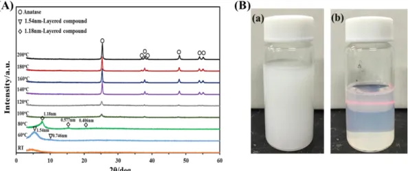
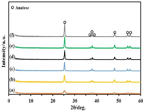
The X-ray powder diffraction (XRD) is an important method for the structural
phases are shown in Figure 1.2. The characteristic diffraction peaks of anatase are (101),
(103), (004), (112), (200), (105) and (211) planes. The characteristic diffraction peaks of rutile are (110), (101), (200), (111), (210), (211) and (220) planes. The main characteristic
diffraction peaks of brookite are (120), (111) and (121) planes.
The weight percentage of each crystal phase in the TiO2 nanocomposite can be
calculated from individual diffraction peaks based on formulas:8 𝑊𝐴 = 𝑘𝐴𝐼𝐴 𝑘𝐴𝐼𝐴 + 𝐼𝑅+ 𝑘𝐵𝐼𝐵 𝑊𝑅 = 𝐼𝑅 𝑘𝐴𝐼𝐴+ 𝐼𝑅 + 𝑘𝐵𝐼𝐵 𝑊𝐵 = 𝑘𝐵𝐼𝐵 𝑘𝐴𝐼𝐴+ 𝐼𝑅 + 𝑘𝐵𝐼𝐵
where WA, WR and WB represents the weight fraction of anatase, rutile and brookite,
respectively, and IA, IR and IB represents the integrated intensities of anatase (101) plane,
rutile (110) plane and brookite (121) plane, respectively. The optimized correction
Figure 1.2. Typical XRD patterns of anatase, rutile and brookite phases.
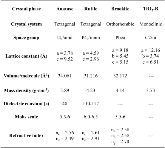
The different crystal structures of TiO2 polymorphs exhibit the different physical
properties. The volume/molecule, mass density, dielectric constant, Mohs scale and refractive index are listed in Table 1.1.
Table 1.1. Structural parameters and physical properties of anatase, rutile, brookite and TiO2-B phases.
1.2.2 Electronic Band Structure of TiO
2Polymorphs
photocatalytic and photovoltaic behaviors of TiO2 polymorphs and TiO2 nanocomposites.
The bandgap values of TiO2 phase can be determined by diffuse reflectance
measurements from the tangent lines to the plots of the modified Kubelka-Munk function
A = B(hv-Eg)2/(hv), where A, B, hv and Eg represent the absorption coefficient, absorption
constant, incident photon energy and bandgap value.10 The positions of the flatband potential (EFB) and the quasi-Fermi level (*Ef) of an n-type semiconductor TiO2 are the
same and very close to the lower edge of the conduction band.9 The Mott-Schottky method was usually used to measure the TiO2 flatband potential (EFB), which can be
regarded as the low edge of conduction band potential (ECB) and the valance band
potential (EVB) can be calculated from EVB = Eg - EFB.10 It has been reported that the
valence band position appears to be rather insensitive to the lattice structure of anatase
and brookite TiO2, namely, the valence band positions of anatase and brookite TiO2 are
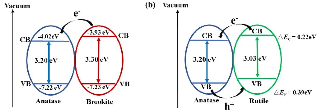
very close.11 Tay et al.12 have measured the E
FB of -0.48 and -0.57 V vs NHE at pH 7,
corresponding to the vacuum energy level of -4.02 and -3.93 eV for anatase and brookite particles, respectively. It can be concluded that the conduction band of brookite phase
positioned by about 0.09 eV more highly than that of anatase phase. And they have also measured the bandgap energies of 3.20 and 3.30 eV for anatase and brookite particles,
respectively. The difference in bandgap energies of anatase and brookite of 0.1 eV coincides well with the shift of the potentials of conduction band (0.09 eV). Therefore,
the electrons will transfer from the conduction band of brookite to that of anatase and the schematic illustration of band edges and transfer of photogenerated electron and hole is
shown in Figure 1.3a.
Scanlon et al.13 have provided enough evidences to prove that the conduction band
band value of rutile is positioned by about 0.39 eV higher than that of anatase from the
computational analyses and HR-XPS experiments. Therefore, the electron affinity of anatase is higher than rutile and brookite, that is, the photogenerated conduction electrons
will flow from rutile to anatase, while the hole affinity of rutile is higher than anatase, that is, the photogenerated valance holes will flow from anatase to rutile. The schematic
illustration of band edges and transfer of photogenerated electron and hole is shown in Figure 1.3b.
Figure 1.3. Schematic illustration of band edges and transfer of photogenerated electron and
hole of (a) anatase and brookite composite and (b) anatase and rutile composite.
1.2.3 Thermodynamic Stability of TiO
2Polymorphs
Rutile is thermodynamically stable, while anatase and brookite are
thermodynamically metastable, which are readily transformed to rutile by heat-treatment.14 At present, it is unclear which is more thermodynamically stable for brookite and anatase. Ye et al. have reported that brookite transforms to anatase and then to rutile.15 Conversely, it has been reported also that the thermodynamic phase stability for the three
polymorphs is in an order of rutile > brookite > anatase.16 Thermodynamic stability and the transformation sequence are dependent also on particle-size. Zhang et al. have
reported that if particle sizes of the three nanocrystalline phases are equal, anatase is most
thermodynamically stable in the crystal sizes range of less than 11 nm, brookite is most stable in the crystal size range of 11 to 35nm, and rutile is most stable in the crystal size
range of greater than 35 nm.17
The solution processes generally favor the anatase phase and brookite phase is
observed sometime as a by-product in an acidic medium at low temperature.12,13 The acidic and alkaline conditions affect strongly on the formation of TiO2 polymorphs.
Cheng et al. explained explicitly the pH effect on the formation of TiO2 phases.18 The
solution pH is higher, the degree of hydrolysis is higher due to the more the OH ligands,
which favors edge-shared bonding for the formations of anatase or brookite. Under sufficiently high acidity, the edge-shared bonding is suppressed, and the corner-shared
bonding can easily take place, resulting in rutile. Barnard et al. have investigated the phase stability of anatase and rutile nanoparticles based on surface free energies and
surface tensions obtained from first principles calculation and demonstrated that the anatase nanoparticles are stabilized by surface adsorbates containing a large fraction of
hydrogen, whereas rutile nanoparticles are stabilized by surface adsorbates containing a large fraction of oxygen.19
1.3 Surface Structures and Surface Energy of TiO
2Polymorphs
1.3.1 Surface Structures of Stoichiometric TiO
2Polymorphs
1.3.1.1 Surface Structures of Stoichiometric Anatase TiO
2structure of anatase.20 The anatase surface structures of the relaxed stoichiometric {111}, {001}, {010}, and {101} facets are shown in Figure 1.4. Both saturated six-fold coordinate titanium (Ti6c) atoms and unsaturated five-fold coordinate titanium (Ti5c)
atoms are present with a ratio of Ti6c/Ti5c=1:1, as well as unsaturated two-fold coordinate
oxygens (O2c) and saturated three-fold coordinate oxygens (O3c) atoms with a Ti-O-Ti
angle of 102o on the {101} facet. On the {010} facet, the outermost Ti atoms are unsaturated Ti5c atoms as well as saturated Ti6c atoms on the second layer. In addition,
both O2c and O3c are present on the surface with a Ti-O-Ti angle of 103o. On the {001}
facet, only unsaturated Ti5c atoms are present as well as both O2c and O3c with a Ti-O-Ti
angle of 146o. On the {111} facet, both unsaturated Ti3c atoms and Ti5c atoms are present
with a ratio of Ti3c /Ti5c=1:3 on the top layer as well as O2c.
Figure 1.4. Anatase surface structures of the relaxed stoichiometric {111}, {001}, {010} and {101}
facets.20 (Copyright@ 2013 American Chemical Society)
1.3.1.2 Surface Structures of Stoichiometric Rutile TiO
2Ramaoorthy et al. have presented the density-functional investigation of the surface
structure of rutile.21 The rutile surface structures of the relaxed stoichiometric {110}, {100}, {011} and {001} facets are shown in Figure 1.5. On the {110} facet, the surface
unit cell has Ti atoms lying in a centered rectangular arrangement, with the atoms at the cell corners being saturated Ti6c atoms, while the atoms in the center are unsaturated Ti5c
atoms. Rows of saturated O3c atoms lie in the plane of the Ti atoms, connecting the chains
Ti5c atoms as well as unsaturated O2c atoms. On the {011} facet, all the Ti atoms on the
surface are unsaturated Ti5c atoms as well as unsaturated O2c atoms at the highest level
on the surface and saturated O3c atoms at a level below that of the surface Ti atoms. On
the {001} facet, all the Ti atoms on the surface are unsaturated four-fold coordinate (Ti4c)
titanium atoms as well as unsaturated O2c atoms.
Figure 1.5. Rutile surface structures of the relaxed stoichiometric {110}, {100}, {011} and {001}
facets.21 (Copyright@ 1994 American Physical Society)
1.3.1.3 Surface Structures of Stoichiometric Brookite TiO
2Gong et al. have presented the density-functional investigation of the surface structure of brookite.22 The brookite surface structures of the relaxed stoichiometric
{100}, {010}, {001}, {110}, {011}, {101}, {111}, {210} and {120} facets are shown in
and O2c atoms are exposed on the facet. The unsaturated Ti4c and O2c atoms as well as
saturated Ti6c and O3c atoms are exposed on the {010} facet. The unsaturated Ti4c and O2c
atoms as well as saturated Ti6c and O3c atoms are also exposed on the {001} facet. On the
{110} facet, unsaturated Ti4c and O2c atoms are exposed at the step edges, while O3c, O2c,
Ti6c and Ti5c occur at the terraces. The {011} facet exposes unsaturated Ti4c, Ti5c and O2c
as well as saturated Ti6c and O2c atoms. The {101} facet exposes unsaturated Ti4c, Ti5c
and O2c as well as saturated Ti6c and O3c atoms. The {111} facet exposes unsaturated Ti4c,
Ti5c and O2c atoms. The {210} facet exposes unsaturated Ti5c and O2c atoms as well as
saturated Ti6c and O3c atoms. The {120} facet exposes unsaturated Ti4c, Ti5c and O2c atoms
as well as saturated Ti6c and O3c atoms.
Figure 1.6. Brookite surface structures of the relaxed stoichiometric {100}, {010}, {001}, {110},
{011}, {101}, {111}, {210} and {120} facets.22 (Copyright@ 2007 American Physical Society)
1.3.2 Surface Energies of Crystal Facets of TiO
2Polymorphs
The surface energy is defined as the excess energy at the surface of a material
compared to the bulk. The surface energy (γ) of each facet can be calculated by γ = (Eslab
- nEbulk)/2A, where Eslab is thetotal energy of the slab, Ebulk is thetotal energy of the bulk
per unit cell, n is the number of bulk unit cells contained in the slab, and A is the surface area of each side of the slab.20-23
Xu et al. have calculated the surface energies of anatase TiO2 based on the
density-functional theory (DFT), as implemented in the VASP code.24 The exchange-correlation energy can be represented by the generalized-gradient approximation (GGA) of Perdew-Burke-Ernzerhof (PBE). The Ti 3s23p63d24s2 and O 2s22p4 were treated as valence
electrons. The energy cutoff for the plane-wave basis set is 400 eV. The supercells which
are constructed from the relaxed unit cell of TiO2 are periodically repeated along the
surface normal and separated by vacuum layers. The calculated surface energies are 1.61,
0.95, 0.57 and 0.43 J/m2 for {111}, {001}, {010}, and {101} facets of anatase. In general, surface energies appear to be related to the presence of unsaturated Ti atoms.
Furthermore, the surface energy approximately increases with the increase of the density of unsaturated Ti atoms.
Ramamoorthy et al. have calculated the surface energies of rutile TiO2 based on the
density-functional theory (DFT).21 A cutoff of 25 Ry is used for the valence electron wave functions, which included the Ti 3s23p63d24s2 and O 2s22p4. The total energies of periodic slabs of TiO2 can be calculated using the LDA for the exchange and correlation energy,
with the Ceperley-Alder form of the exchange-correlation potential. The calculated surface energies are 15.6, 19.6, 24.4 and 28.9 meV/ (a.u.2) for {110}, {100}, {011}, and
{001} facets of rutile. Also, the surface energy approximately increases with the increase of the density of unsaturated Ti atoms.
Gong et al. have calculated the surface energies of brookite TiO2 based on the
density-functional theory (DFT).22 Electron-ion interactions can be described with
electrons from Ti 3s23p63d24s2 and O 2s22p4. Plane-wave basis set cutoffs for the smooth part of the wave functions and the augmented density are 25 and 200 Ry, respectively.
The calculated surface energies are 0.88, 0.77, 0.62, 0.85, 0.74, 0.87, 0.72, 0.70 and 0.82 J/m2 for {100}, {010}, {001}, {110}, {011}, {101}, {111}, {210} and {120} facets of
1.3.3 Surface Energy Effect on Crystal Shape (Wulff Construction)
The shape of a thermodynamically stable macroscopic crystal can be given by the
standard Wulff construction and the calculated surface energy based on the surface energy minimization. According to the Wulff construction and calculated surface energy, the
equilibrium shape of anatase is a slightly truncated tetragonal bipyramid enclosed with
the eight isosceles trapezoidal surfaces of {101} and two top squares of {001}, as shown in Figure 1.7.20 The most stable {101} facet is mainly exposed, and the exposed percentage of {101} facet is predicted to be as high as 94%.
Figure 1.7. The equilibrium shape of a TiO2 crystal in the anatase, rutile and brookite based on the Wulff construction and the calculated surface energies.20-22 (Copyright@ 2001, 1994, 2007
American Physical Society)
The equilibrium shapes of rutile and brookite crystals are also predicated based on
the Wulff construction and the surface energies. The shape of rutile crystal composes with major facets of {111}, {210}, {010} and {001} facets and small numbers of {011}, {101}
and {100} facets,21 while the shape of brookite crystal composes with major facets of {111}, {210}, {010} and {001} facets and small numbers of {011}, {101} and {100}
facets,22 as shown in Figure 1.7.
even though the surface energy of {010}-facet is between those of {001} and {101}-facet.
The equilibrium shape predicated based on Wulff construction is conducted in vacuum at absolute zero temperature, which is different from the conditions in air at room
temperature. Barnard et al. have systematically investigated the chemical adsorption effects on the morphology and phase stability of TiO2 using a thermodynamic model
based on surface free energies and surface tensions obtained from first principles calculations and indicated that surfaces under acidic and alkaline conditions had a
significant influence on both the shape of the nanocrystals.19 When hydrogen atoms are adsorbed dominantly on the surface, the shape of the anatasenanoparticles corresponds
to the Wulff construction result, as shown in Figure 1.8a-c, while the anatase nanoparticles become elongated when oxygen atoms are adsorbed dominantly on the
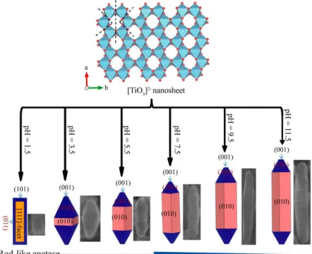
surface, resulting in the {010}-faceted “belt” particles, as shown in Figure 1.8d, e. Furthermore, the conclusions obtained from the theoretical calculation have been proved
by the experimental results from our lab. Du et al. in our lab have synthesized anatase TiO2 nanorod via topotactic transformation reaction from exfoliated protonated layered
titanate H2TiO3 nanosheets and demonstrated that the increase of pH is benefit to the
higher exposure of the {010}-facet, which leads to morphology changing from short
spindle to long spindle, as shown in Figure 1.9. 25
surface adsorbates, (c) hydrated surfaces, (d) hydrogen-poor adsorbates, and (e) oxygenated surfaces.19 (Copyright@ 2013 American Chemical Society)
Figure 1.9. Transformation reaction mechanism from layered metatitanic lithium oxides to anatase
TiO2 nanocrystal and simulated crystalline shapes.25 (Copyright@ 2015 American Chemical Society)
1.3.4 Surface Energy Effect on Bandgap (Quantum Size Effect)
The percentage of surface atoms of TiO2 nanocrystals increases significantly with
the decrease of the crystal size, which can cause changes of the bandgap and the lattice
parameters. The effects caused by the crystal size are called size effects26,27 or quantum size effects.28-33 The bandgap increases with the size decreasing, and the charge carriers show quantum mechanical behavior. A clear bandgap blue shift is observed in a crystal size range of < 2 nm by quantum size effect for anatase nanocrystals. For example, anatase
from 2 nm to 1nm.33 However, no obvious quantum size effect is observed for anatase TiO2 nanocrystals when the crystal size surpasses 2 nm.28-32
The surface effect can cause long-tail optical absorption and red-shifted optical
emission. Therefore, different truncated facets of TiO2 crystals display distinctly different
electronic behaviors. Ariga et al.34 experimentally and theoretically exhibited a surface-state-mediated photochemical reaction on the {001} facet for photooxidation of formic acid under visible light, and the {001} facet had a smaller bandgap than that of {110}
facet because the Ti4+ and oxygen orbitals on the {001} facet resulted in the energy levels near the conduction band minimum and valence band maximum, respectively, leading to
bandgap narrow, seen in Figure 1.10a. Tao et al.35 found that a new pure TiO2 phase forms
on the surface of rutile TiO2 {011} facet with a bandgap of only ∼2.1 eV by oxidation of
bulk titanium interstitials which is obtained in vacuum by repeated ion sputtering and vacuum annealing to 650 oC, matching it closely with the energy of visible light. The new
{011} facet had extra states within the bulk bandgap with a maximum at 2.1 eV blow EF and moved the valence band maximum toward EF by 0.3 eV, resulting in reduction by
0.9 eV of bandgap, seen in Figure 1.10b.
latticework structure,34 (Copyright@ 2009 American Chemical Society) and (b) band diagram of the (011) surface compared with the bulk.35(Copyright@ 2011 Macmillan Publishers Ltd.)
1.3.5 Surface Effect on Chemical Properties
The atoms on the surface are normally not saturated and have many dangling bonds when the surface atoms are truncated from the chemically stoichiometric bulk. One of the
surface effect is that the unsaturated bonds on the surface cause high surface activities to adsorb the adjacent molecules.26,27 Different surface will result in different physicochemical properties. It is well documented that the –OH groups are energetically favored on the {001} and {010} facets while water molecules are only adsorbed on the
{101} facet, and the schematic illustration of the –OH groups adsorbed the {001} surface and water molecules adsorbed on the {101} without dissociating is shown in Figure
1.11.36,37
Figure 1.11. (a) – OH groups adsorbed on {001} surface and (b) water molecules adsorbed on
1.4 Photocatalytic Reaction
1.4.1 Semiconductors as Photocatalyst
Semiconductor has an electrical conductivity value falling between the conductor and the insulator, which can act as sensitizers for light-induced redox process because of
the electronic structure with a filled valence band and an empty conduction band.38,39 Semiconductors as photocatalyst have been researched for a long time. As early as 1955,
Markham et al. researched the photocatalytic properties of ZnO, Sb2O3 and TiO2 under
UV light.40 In 1964, Kato et al. researched the photocatalytic oxidation of tetralin by a
TiO2 suspension.41 Subsequently, McLintock et al. investigated the photocatalytic
oxidation of ethylene and propylene in the presence of oxygen adsorbed on TiO2.42 The
great discovery of “Honda-Fujishima Effect” was found by Fujishima and Honda in 1972
and they demonstrated that the water could be electrochemically photolyzed into H2 and
O2 at a TiO2 electrode and a platinum black electrode under UV-light irradiation.43
Thereafter, numerous studies about the photocatalysis have been carried out. Bard et al.44
have reported the photodecomposition of cyanide in the solution by TiO2 suspension in
1977, which starts the direction of photodegradation of organic pollution. The nanosized
TiO2 particles as the photocatalyst has attracted enormous attentions in 1980s due to its
high performance. Since Serpone et al.45 coupled two kinds of semiconductors CdS and TiO2 together, resulting in excellent charge separation for the first time in 1984, many
researches have been carried out extensively. Wen et al.46 in our lab reported the first challenge on synthesis of {010}-faceted anatase TiO2 nanocrystals which exhibit a much
higher photocatalytic performance than that of the normal anatase nanocrystals in 2006, and since then the facet effect on the photocatalytic activity has attracted lots of attention.
Recently many studies focus on visible light response photocatalysts by modification of
the semiconductors, including doping, coupling and capping of semiconductor, which will be mentioned in section 1.7.
1.4.2 Semiconductor
Photocatalytic Materials
Many semiconductors, such as TiO2, SrTiO3, ZnO, Fe2O3, WO3, SnO2, ZrO2, CdS,
ZnS, SiC, GdSe, PbS, GaP, GaAsP and GaAs, have been studied as the photocatalysts.
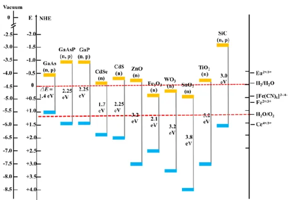
47-49 The photocatalytic abilities of the semiconductors depend on the bandgap and band
edge position of semiconductors and redox potential of adsorbates. Figure 1.12 shows the bandgaps and band edge positions of several semiconductors in contact with an aqueous
electrolyte potential at pH 1.39 The leftmost scale corresponds to the vacuum energy level and the adjacent scale corresponds to the normal hydrogen electrode (NHE) potential,
while the rightmost scale corresponds to the NHE potential of several redox couples. And the sides with low potentials (blue) represent the valence bands while the high potentials
(orange) represent the conduction bands of semiconductors. The energy level at the bottom of conduction band determines the reducibility of photogenerated electrons while
the energy level at the top of valence band determines the oxidizability of photogenerated holes. The photogenerated electrons of semiconductors can reduce the electron acceptor
species when the reduction potential of the acceptor species locates blow the conduction bands of semiconductors while the photogenerated holes can oxidize the hole acceptor
species when the oxidation potential of the acceptor species locates above the valence bands of semiconductors.
Figure 1.12. Bandgap and band edge positions of several semiconductors in contact with an aqueous
electrolyte potential at pH 1.
Most of the semiconductors have the distinct drawbacks as the photocatalysts. PbS,
GdSe, GaP, GaAsP and GaAs are instability in photocatalytic reactions in aqueous media and they are toxic.47 Fe
2O3, WO3 and SnO2 possess a conduction band edge at an energy
level below the hydrogen reduction potential, therefore cannot be used for the water splitting.48 ZnO is unstable because it readily dissolves in water to yield Zn(OH)
2.49 The
TiO2 is close to be an ideal photocatalyst because it has a strong redox potential and it is
stable in the photocatalytic reaction, nontoxic and cheap. However, it has a disadvantage,
1.4.3 Photocatalytic Reaction of TiO
2Polymorphs
1.4.3.1 Reaction Mechanism of TiO
2Polymorphs
The process of heterogeneous photocatalysis with the semiconductor TiO2 involves
two processes: (1) photophysical and (2) photochemical processes.50-52 (1) The photophysical process involves four steps: the excitation, bulk diffusion and surface
transfer of the charge carrier as well as the charge carrier annihilation. When the TiO2
adsorbs a photon with the energy higher than the bandgap energy of the TiO2, an election
in the filled valence band is excited to the empty conduction band and a hole is formed at valence band, that is, an electron-hole pair (carrier) is generated. The photogenerated
electron and hole will separate and transfer to the TiO2 surface and then transfer to the
adsorbates adsorbed on the TiO2 surface. Meanwhile, the carrier annihilation also can
occur by the recombination of electron and hole on the TiO2 surface, electron and hole
recombination inside TiO2 bulk phase and trapping of electron and hole by lattice defects.
(2) The photochemical process involves two steps: the oxidization of adsorbate by photogenerated hole and the reduction of adsorbate by photogenerated electron. The
Figure 1.13. Schematic illustrating heterogeneous photocatalytic reactions on TiO2 semiconductor The TiO2 photocatalysts can be applied to (1) photocatalytic water splitting to H2
and O2,12,43,53-55 (2) CO2 photoreduction to fuels,56-60 and (3) photocatalytic degradation
of organic pollutant.27,61-64
(1) The hydrogen production by water splitting over a single TiO2 photoanode
connected with a Pt electrode through an external load under UV light has been
discovered by Fujishima and Honda in 1972.43 The photocatalytic water splitting accords to the following schemes:
TiO2 + 2 hv → 2 e- + 2 h+ (excitation of TiO2 by light)
2 h+ + H
2O → 1/2 O2 + 2 H+ (at the TiO2 electrode)
2 e- + 2 H+ → H2 (at the Pt electrode)
The overall reaction is
H2O + 2 hv → O2 + H2
reduction, the same as that of the hydrogen production. The photoreduction products of
CO2 are CO, CH4, CH3OH, HCOOH and so on.56-60 The fundamental mechanism is
summarized as follows: TiO2 + 2 hv → 2 e- + 2 h+ H+ + e- → H· H· + H·→ H2 2 CO2 + 4 e- → 2CO + O2 CO + 4 e- + H+→CH4 + H2O
(3) The photogenerated hole oxidization and photogenerated electron reduction
simultaneously occur on the TiO2 surface in the process of photocatalytic degradation of
organic pollutant solution. The photogenerated holes can be trapped by OH- and H2O
adsorbed on the TiO2 surface and oxidized to ·OHradical which can oxidize the organic
pollutant into inorganic molecules CO2, H2O and so on. The photogenerated electrons can
be trapped by O2 adsorbed on the TiO2 surface and reduced to ·O2- radical, which can
oxidize the organic pollutant into inorganic molecules CO2, H2O and so on. Meanwhile,
the ·O2- radical can further transfer to H2O2 by protonation, which can react with ·O2-
radical to form the ·OH radical. The fundamental mechanism is summarized as
follows:63,64 TiO2 + 2 hv → 2 e- + 2 h+ h+ + H2O → ·OH + H+ e- + O 2 → ·O2- ·O2- + H+ → HO2· 2 HO2· → O2 + H2O2 H2O2 + ·O2- → ·OH + OH- + O2
1.4.3.2 Factors Influence Photocatalytic Activity
The structure,56,57,61 surface area,27 crystallinity,27 and crystal-facet exposed on the
crystal surface25,46,65-67 of TiO2 strongly affect its photocatalytic performances. It is
considered generally that the anatase phase exhibits excellent photocatalytic activity in
the TiO2 polymorphs because of its surface-adsorbed hydroxyl radicals and a slow
recombination of electrons and holes, while rutile phase exhibits low photocatalytic
activity because of its high recombination of electrons and holes.68 Much less studies have been reported on the photocatalysis of brookite because the brookite single phase is
difficult to be synthesized, especially, the nanosized brookitecrystals, and therefore its photocatalytic activity is still controversial.56,57,61 The TiO
2 nanocomposites exhibit a
higher photocatalytic activity than those of their single phases, respectively, because a synergistic effect can promote effective separation of the photogenerated electron-hole
pairs in the nanocomposites.13,16,56,57,70
Since the photocatalytic reaction occurs at the surface of TiO2 surface, the surface
area plays an important role in photocatalytic reaction. In general, the surface area is higher, namely, the more reactive site, and therefore, the photocatalytic activity is higher. However, the surface area doesn’t play the decisive role in photocatalytic reaction. The
diffusion rates of the photogenerated electrons and holes mainly decide the reaction rates
of photocatalytic reaction, rather than the adsorption-desorption rate of adsorbates on the surface. Furthermore, highly surface area tends to small particle size with decreasing
crystallinity, which reduces the photocatalytic activity.27
In general, the high crystallinity facilitates the diffusion of the photogenerated
electrons and holes, favoring the enhancement of photocatalytic activity. The lattice defects in the crystal will increase with decreasing crystallinity, which is adverse to
photocatalytic activity. 27
The crystal-facet exposed on the crystal surface of TiO2 strongly affect its
photocatalytic performances because different crystal facets exhibit different surface
energies and surface electronic band structures, which will affect the physicochemical properties on the surface. The detailed crystal-facet effect will be mentioned in the next
section.
1.5 Facet Effect on Photocatalytic Reaction of TiO
2Polymorphs
1.5.1 Synthesis of {101}-Faceted Anatase TiO
2and Photocatalytic
Behavior
As mentioned above, the {101}-facet with the lowest surface energy is the most thermodynamically stable and easily appears on the crystal surface which can be obtained
by coarsening in terms of Ostwald ripening. Amano et al.65 synthesized the octahedral
anatase crystallites with abundant {101} facets and a size less than 100 nm by
hydrothermal treatment of K-titanate nanowires with a size of 5-15 nm in diameter and hundreds of nanometers in length, as shown in Figure 1.14, and found that the
{101}-faceted anatase crystallites exhibited relatively high photocatalytic activity for decomposition of organic compounds and low activity for hydrogen evolution.
Meanwhile, the {101}-faceted anatase nanobelt and nanosheets were synthesized from the calcination of H-titanates which synthesized by hydrothermal treatment of TiO2
powder in a high-concentration NaOH aqueous solution as well as acid exchanging.
{101}-faceted nanospheres with an identical crystal phase and similar specific surface
area because the nanobelts yielded an enhanced reactivity with molecular O2, facilitating
the generation of superoxide radical, as well as the nanobelts have higher charge carrier
mobility and provided the pathway for transport of charge carriers throughout the longitudinal direction, which was expected to facilitate the charge separation.65,74
Figure 1.14. SEM image of (a) titanate nanowires and (b, c) particles after hydrothermal reaction of
titanate nanowires, and (d) TEM image and electron diffraction pattern of octahedral bipyramid.65 (Copyright@ 2009 The Royal Society of Chemistry)
1.5.2 Synthesis of {010}-Faceted Anatase TiO
2and Photocatalytic
Behavior
Since Wen et al.46 reported the first challenge on {010}-faceted anatase TiO2
nanocrystals which exhibit a much higher photocatalytic performance than that of the
normal anatase nanocrystals in 2006, many studies on the {010}-faceted anatase nanocrystals have been carried out. 25,75-79 Our group developed an environment-friendly
route to synthesize {010}-faceted anatase TiO2 nanocubes, nanorods via topotactic
transformation reaction from different exfoliated layered titanate nanosheets.25,75,76 This process includes three steps reactions, synthesis of layered titanate, exfoliation of layered
titanate, and topotactic transformation of the nanosheets to anatase nanocrystals without use of hydrofluoric acid. Meanwhile, some researchers also reported similar methods for
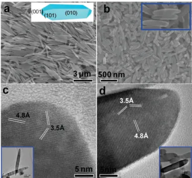
synthesis of {010}-faceted anatase tetragonal faceted nanorods by hydrothermal treatment of Na-titanate nanotubes and lepidocrocite-type protonated titanate
H0.68Ti1.83O4, seen in Figure 1.15.80,81
Figure 1.15. SEM and HRTEM images of (a) micron-sized and (b) nanosized TiO2 rods. The insets in (a) and (b) show a schematic shape of an anatase rod with {010}, {101}, {001} and a
high-magnification SEM image of nanosized TiO2 rods. The insets in (c) and (d) are the low-magnification TEM images of the micron- and nanosized rods.78 (Copyright@ 2010 The Royal
Society of Chemistry)
In addition, the rhombic-shaped {010}-faceted anatase nanocrystals and porous anatase TiO2 microspheres composed of {010}-faceted nanobelts have been successfully
synthesized using the organic titaniums (Ti(OBu)4 or Ti(OC4H9)4) as Ti source and the
organic capping agents (oleylamine or glycerol) which can selectively adsorb on the
crystals surfaces.77-79
For the synthesis of anatase TiO2 nanocrystals with {010} facet on the surface,
surface fluorination route to reduce the surface energy of the high-energy surface by adsorption F- on the surface is an effective and normal method. The {010}-faceted anatase
TiO2 nanocubes and anatase TiO2 nanosheets have been successfully synthesized by the
Figure 1.16. (a) SEM image, (b) TEM image, (c) HRTEM image, and SAED pattern (inset of c) of
TiO2 nanosheets, as well as (d) SEM image of anatase TiO2 cuboids. (Copyright@ 2013 American Chemical Society)
The synthesized anatase {010}-faceted TiO2 crystals exhibited a superior
photocatalytic degradation of organic pollutants, photocatalytic conversion of CO2 into
CH4 and H2 evolution because of the its superior surface atomic structure (100% Ti5c
atoms for active reaction sites) and surface electronic band structure (more strongly reducing electrons in the conduction band) of {010}-facet.78-83
1.5.3 Synthesis of {001}-Faceted Anatase TiO
2and Photocatalytic
Behavior
Since the surface free energy of the {001} facet (0.90 J/m2) is higher than that of other facets including {010} facet (0.53 J/m2) and {101} facet (0.44 J/m2), it is a big challenge to prepare uniform {001}-faceted anatase TiO2 singe crystals.20,24 In 2008,
Yang et al.66 have made a breakthrough in the synthesis of uniform truncated tetragonal bipyramid anatase TiO2 single crystals with 47% of {001} facets using the TiF4 as Ti
source and hydrofluoric acid as morphology controlling agent, as shown in Figure 1.17.
And they have made attempts to explore the effects of various adsorbate atoms with a systematic investigation of 12 non-metallic atoms based on first-principle calculations and revealed that termination with F atoms not only yields the lowest value of γ for both
(001) and (101) surfaces, but also results on (001) surfaces that are more stable than (101)
surfaces. These results revealed that anatase TiO2 singe crystals with high-percentage
{001} facets can be achieved by surface fluorination route. Subsequently, they
synthesized high-quality anatase TiO2 single-crystal nanosheets with 64% of {001} facets
using the TiF4 as Ti source and 2-propanol as a synergistic capping agent and reaction
medium together with HF and found that the presence of 2-propanol can enhance the stabilization effect associated with fluorine adsorption over the (001) surfaces.84
Figure 1.17. (a) SEM image and (b) selected-area electron diffraction pattern of {001}-faceted
anatase single crystals.66 (Copyright@ 2008 Nature Publishing Group)
Consequently, the surface fluorination route was widely applied to prepare the {001}-faceted anatase TiO2 crystals. The micro-size microspheres TiO2, micro-size
truncated tetragonal bipyramids TiO2, micro-size flower-like TiO2, nanosized TiO2 single
crystals as well as TiO2 nanosheets with different exposed percentages of {001}-facet
were successfully synthesized though different Ti resources, such as Ti powder,86 TiF4,66,87 Ti(SO4)2,88 Ti foil,89,93 Ti(OBu)4,90,91and Ti(OC4H9)492 as well as different
fluorine sources, such as HF,66,81,86,89-93 NH4HF2,88TiF4,66,87 and 1-methyl-imidazolium
tetrafluoroborate.87
The role of HF for preservation of {001} facet is explained by Zhang group. Zhang
et al.94 firstly reported a selective etching phenomenon on the {001} faceted anatase TiO2
crystal surface by HF, and the related HF etching mechanism based on the density
functional theory (DFT) and demonstrated that HF stabilized the grown {001} facets at low HF concentrations, but selectively etched the grown {001} facets at high HF
concentrations through the surface -OH replacement and -TiOF2 dissolution processes.
Subsequently, Zhang et al.93 reported that anatase TiO
2 crystals with exposed {001} facets
can be directly fabricated on Ti foil substrate by controlling the solution pH ≤ 5.8. When pH is increased to near neutral and beyond, the insufficient concentration of HF
dramatically reduces the extent of surface fluorination, leading to the formation of anatase TiO2 crystals with {101} facets and titanate nanorods/nanosheets. DFT calculations have
confirmed that {001}-faceted anatase TiO2 surface fluorination can occur only through
dissociative adsorption of molecular form HF under acidic conditions. This confirms that
the presence of molecular form of HF but not F- is essential for preservation of exposed {001} facets of anatase TiO2.
Some researchers have synthesized anatase TiO2 with a high percentage of {001}
facet by a fluorine-free route. Chen et al.95 hydrothermally synthesized uniform
exposed {001} facet using titanium isopropoxide (TTIP), diethylenetriamine (DETA) and
isopropyl alcohol (IPA) without fluorine. Li et al.96 synthesized {001}-faceted
single-crystalline anatase TiO2 nanofibers from layered potassium titanate K2Ti2O5 via topotactic
transformation.
The synthesized {001}-faceted anatase TiO2 crystals exhibited excellent
photocatalytic activities under UV light irradiation which was ascribed to the unique surface atomic structure with 100% Ti5c atoms and a Ti-O-Ti angle of 146o of
{001}-facet.85-93 The water molecules were chemically dissociated on the {001}-facet which facilitated the transfer of photogenerated carries and the formation of reactive radicals as
well as the organic pollutant molecules were also chemically dissociated on the {001}-facet which enhanced the interfacial charge transfer and photocatalytic reaction kinetics.
Except for the dissociated adsorption effect, the {001}-facet promoted the charge separation because abundant oxygen deficiency existed in the {001}-facet, as well as the
synergistic effect between the high-energy {001}-facet and low-energy {101}-facet facilitated the charge separation. In summary, the dissociated adsorption of water and
organic pollutant molecules on the {001}-facet and enhanced charge separation are the main factors accounting for the excellent photocatalytic activity for {001}-facet.
1.5.4 Synthesis of [111]-Faceted Anatase TiO
2and Photocatalytic
Behavior
Up to now, only a few of studies have been reported on [111]-faceted anatase
nanocrystals. As seen in the HE-TEM image in Figure 1.18,two sets of lattice fringes with d-values of 0.351 nm corresponding to the (101) and (011) plane of the anatase phase
and an interfacial angle of 82o between these two lattice fringes which agreed with the theoretical value of 82.1o were shown in the anatase nanocrystals. The results reveal that the surface of the nanocrystal is vertical to [111] crystal zone axis and the facet cannot be
denoted by a simple Miller index plane {hkl}, therefore, is referred to the [111]-facet. The [111]-facet is different from the {111}-facet because the anatase belongs to tetragonal
system but not cubic system.
Xu et al.24 have synthesized the [111]-faceted square-like plate anatase TiO2
nanocrystals via TiF4 as Ti resource and both F- and ammonia as the capping reagents, as
shown in Figure 1.18, and demonstrated that the [111]-faceted anatase TiO2 nanocrystals
exhibited an excellent photocatalysis on the H2 evolution compared to those of the TiO2
samples with majority {101},{010} and {001} facets because of its excellent electronic
band structure and abundant oxygen vacancies on the surface. Zhang et al.97 synthesized
[111]-faceted anatase TiO2 nanocrystals by a hydrothermal route with NH4+ and F- as
capping agents and indicated that the [111]-faceted nanocrystals exhibited a better selectivity than that of the {001}-faceted nanocrystals in the photocatalytic degradation
of MB and an excellent photocatalytic MB decomposition as much as 2-3 times than that of {001}-faceted TiO2 nanosheets and P25. However, these studies have made a mistake
on the facet assignment, namely they treated the [111]-facet as the {111}-facet and explained the superiority of the {111}-facet using the experiment results of the
[111]-facet.
Besides the fluorination effect for synthesis of [111]-facet, our group has synthesized
the [111]-faceted anatase TiO2 nanocrystals via a topotactic transformation reaction from
different exfoliated layered titanate nanosheets to synthesize [111]-faceted anatase TiO2
photocatalytic for degradation of MB solution.25
Figure 1.18. (a, b) SEM, (c) TEM, and (d) HRTEM images of [111]-faceted single crystalline
TiO2.24 (Copyright@ 2013 American Chemical Society)
1.5.5 Comparison of Photocatalytic Activity of Anatase with Different
Crystal Facets
Some studies have been reported on the comparison of photocatalytic activities of
different faceted anatase nanocrystals. In general, it is considered that the
high-surface-energy facet exhibits a high photocatalytic performance because of its high percentage of undercoordinated titanium atoms. However, some different results have been reported.
Pan et al.83 have reported that the facet-dependent photocatalytic activity for
hydrogen-evolution rate increases in an order of {001} < {101} < {010} and explained that the low
photocatalytic activity of {001}-facet is due to its low bandgap value and the high photocatalytic activity of {010}-facet is due to its favorable surface atomic structure and
surface electronic structure. However, the exposure percentages of the {001} facet of
these samples are 40%, 76% and 53%, respectively. The study has not considered the exposure percentage of the predominant facet of these anatase TiO2 nanocrystals. The
recent researches demonstrated that the facet synergetic effect can affect also the photocatalytic activity. Ye et al.98,99 have reported an opposite order of {010} < {101} < {001} for liquid-phase photocatalytic reduction (O2- generation) and oxidation (·OH
generation) after normalizing specific surface area effect where the exposure percentage
of the predominant facet of these anatase TiO2 nanocrystals is more than 90%. Recently,
Li et al.100 have reported that the photocatalytic activity for degradation of MO solution increases in an order of {101} < {010} < {001} for anatase nanocrystals with a similar bandgap energy of 3.28 eV and high percentage (>86%) of the exposed predominant
facet after normalizing specific surface area effect, which corresponds to the increasing order of surface energy and the relative number of Ti4+ sites with undercoordinated
five-fold coordination environments. Our group demonstrated that the photocatalytic activity for degradation of MB solution increased in an order of non-facet < [111]-facet <
{010}-facet after normalizing specific surface area effect and calculating the exposed percentage of predominant facet, which was in accordance with the increased order of surface
electronic band structure of non-facet < [111]-facet < {010}-facet.25
1.5.6 Synergistic Effect of High-Energy Facet and Low-Energy Facet on
Photocatalytic Activity for Anatase
The studies described above mainly focus on synthesizing the high-energy facets
have demonstrated that the coexistence of the low-energy facet with the high-energy facet
facilitates the charge separation and thereby enhances photocatalytic activity of anatase TiO2.
Truncated tetragonal bipyramidal anatase TiO2 crystals with the {001}-facet and
{101}-facet have been widely used for the study on the synergistic effect between
{001}-facet and {101}-{001}-facet. It has been concluded that the {001}-{001}-facet and {101}-{001}-facet provided the reduction and oxidation sites, respectively. And anatase TiO2 with 45%
{101} and 55% {001} facets which exhibited the highest photocatalytic CO2 reduction
performance,101 anatase TiO2 with 40% {101} and 60% {001} facets which exhibited the
highest photocatalytic degradation of MB solution102 as well as anatase TiO2 with 55%
{101} and 45% {001} facets which exhibited the highest photocatalytic degradation
activity for ·OH radical generation103 have been reported.
Compared with the facet synergistic effect of {101} and {001} facets, the facet
synergistic effect of {010} and {001} facets have rarely been researched. It has been reported that the {101}-{001} facets exhibited excellent photocatalytic activity compared
to the {010}-{001} facets due to the efficient charge separation between the {101} facet and {001} facet because the presence of the low-energy {101} facet facilitates the charge
separation and thereby enhance photocatalytic activity. 82,104,105
1.5.7 Facet Effect on Rutile TiO
2Photocatalytic Activity
The rutile generally exhibits low photocatalytic performance because of low special
surface area and fast charge recombination rate. Analogous to the facet effect for photocatalytic activity of anatase, the facet controlling of rutile has attracted lots of
attention by many researchers.106-113 The rutile generally grows anisotropically along the [001] direction to form a rod morphology with low-percentage exposed {111} top-facet and high-percentage {110} side-facet because the surface energy of {111} facet is higher
than that of {110} facet and the frequently observed morphology tends to bundled or self-assembled nanowires or nanorods. Generally, the existence of Cl- facilitates the formation of rutile phase.106-108
Some researchers also reported the high percentage of high-energy {111}-faceted
rutile. The surface fluorination route usually was used for synthesis of high-energy {111}-faceted rutile. The photocatalytic results demonstrated that {111} facet exhibited a higher
activity than that of {110} facet because more unsaturated O2c modes on the {111} facet
caused higher adsorption and degradation ability, resulting in enhancement of the
photocatalytic activity.109-111 Besides the {110} facet and {111} facet, the high-energy {001} facet has also been reported. The prepared rutile TiO2 nanorods exhibited
considerably enhanced photocatalytic activity compared to bulk rutile TiO2.112,113
1.5.8 Facet Effect on Brookite TiO
2Photocatalytic Activity
Brookite has attracted much less interest because the brookite single phase is difficult to be synthesized, especially, the nanosized brookite crystals, and therefore its
photocatalytic activity is still controversial. The selective control on the exposure of specific crystal facets and research on the facet-dependent photocatalytic activity are still
a challenge.
Some researchers have synthesized that brookite nanosheets and TiO2 nanorods
the crystal surface via a hydrothermal process utilizing TiCl4 or tetrabutyl titanate
(TBOT) as a titanium source and urea as an in situ OH- source and sodium lactate as the complexant.114,115 The prepared brookite TiO2 nanosheets with four {210}, two {101} and
two {201} facets exhibited outstanding activity toward the photocatalytic degradation of organic contaminants superior even to that of P25 due to the exposure of high-energy
facets and the effective suppression of recombination rate of photogenerated electrons and holes by the charge separation effect of coexistence of the low-energy facet with the
high-energy facet.114 And the brookite TiO2 nanorods with dominant {121} facet
exhibited excellent performance for RhB photodegradation due to more undercoordinated
Ti atoms on the {121} facets and a lower VB potential of the TiO2 nanorods, while
brookite TiO2 nanosheets with dominant {211} facet exhibited superior H2 productivity
due to a much higher CB potential of the TiO2 nanosheets.115
1.6 Nanocomposite Effect on TiO
2Photocatalytic Reaction
The TiO2 polymorphs nanocomposites exhibit a higher photocatalytic activity than
those of their single phases, respectively, because a synergistic effect can promote
effective separation of the photogenerated electron-hole pairs in the nanocomposites. Hydrothermal process usually was used to synthesize the anatase-rutile nanocomposite
with different phase compositions by altering the synthesis parameters or in presence of additives. Up to now, much attention has been paid on the high photocatalytic
performance of the anatase-rutile composite. Many researchers have reported that anatase-rutile composite exhibited more efficient photocatalytic performance than that of
that is, the photogenerated conduction electrons will flow from rutile to anatase, while
the hole affinity of rutile is higher than anatase, that is, the photogenerated valance holes will flow from anatase to rutile, leading to more efficient electron/hole separation and
higher photocatalytic performance.13 And some researchers have reported the optimum ratio of anatase-rutile of 4:1 exhibited the highest photocatalytic activity.121-123
In comparison with anatase-rutile nanocomposite, much less the anatase-brookite and brookite-rutile composites have been reported because they are difficult to be
synthesized. As to anatase-brookite composite, some researchers have reported that anatase-brookite composite exhibited more efficient photocatalytic performance than the
pure single phase even the P25 which was attributed to the increased charge separation efficiency resulting from the transfer of photogenerated electrons from brookite to
anatase.12,13,124-127 Meanwhile, several researchers have reported the optimum ratio between anatase and brookite with brookite phase ranging between 20 and 40% for the
highest photocatalytic performance.13,126,127 Only few papers have reported the photocatalytic performance of the brookite-rutile composite which exhibited excellent
photocatalytic performance than that of pure phase and P25.128,129 We think the anatase-brookite nanocomposite is one of the most promising combinations for the enhanced
photocatalytic activity due to the large bandgap of brookite and long lifetime of the photogenerated electro-hole pairs on anatase.
1.7 Visible Light Active TiO
2Photocatalyst
TiO2 is an excellent UV-light response photocatalyst. However, the visible light
approaches including doping, coupling and capping of TiO2 have been studied
extensively to develop the visible light response TiO2 photocatalysts. Some transition
metal cations doped TiO2, such as Fe, Mo, Ru, Os, Re, La, Nd, V, Sm and so on, exhibit
excellent visible light photocatalytic performance because transition metal cations can provide additional energy levels within the bandgap of TiO2.130,131 Xu et al.132 have
reported a metalloid boron (B) doped TiO2 photocatalyst and its excellent active for
degradation of Reactive Brilliant Red under visible light. Many studies have been carried out to develop the visible light response photocatalysts by doping TiO2 with non-metal
anions, such as C, N, F, P and S. These non-metal atoms doped TiO2 photocatalysts exhibit
excellent visible light photocatalytic performance because the mixing of the p orbits of the doped anion with the O 2p orbits shifts the valence band edge upwards, narrowing the bandgap energy of TiO2.133-135 Additional, coupling TiO2 with visible light response
semiconductor particles, such as TiO2-CdS, Bi2S3-TiO2, TiO2-WO3, TiO2-SnO2, TiO2
-MoO3 and TiO2-Fe2O3, can also enhance visible light response photocatalytic
performance by improving the charge separation and extend the energy range of photoexcitation.136,137
1.8
TiO
2Nanocrystals for Dye Sensitized Solar Cells (DSSCs) and
Perovskite Solar Cells (PSCs)
1.8.1 Progress on DSSCs and PSCs
Silicon based solar cells today dominate the photovoltaic market, which have
cell is high because the manufacturing process is complex. Dye sensitized solar cells
(DSSCs) and perovskite solar cells (PSCs) are considered the most promising photovoltaic technologies as the alternatives to traditional silicon-based solar cells
because of low production cost and the high efficiency. 139,140
In 1991, Grätzel and O’Regan139 successfully made a breakthrough in DSSCs by
using a mesoporous TiO2 film with a ruthenium based metallo-organic dye, which have
achieved an efficiency of 7.9%. Now, the highest conversion efficiency has arrived to 12.3% based on a liquid cobalt-based electrolyte and a porphyrin in 2011.141 However,
the improvement of the efficiency becomes the bottleneck of development of DSSCs. Recently, perovskite solar cells (PSCs) based on halide perovskite have attracted
substantial attention because of the high efficiency. In 2006, Miyasaka et al. made the first attempt to use the halide perovskite materials CH3NH3PbBr3 and CH3NH3PbI3 as the
absorber on mesoporous TiO2 in the junction of liquid redoxelectrolytes, which was as an
extension of dye sensitized solar cells and achieved efficiencies of 2.2% and 0.4%.142
They improved the efficiency of this liquid-junction perovskite-sensitized solar cell up to 3.8% in 2009.143 Park et al. demonstrated highly efficient QD-sensitized solar cell based
on perovskite CH3NH3PbI3 with best efficiency of 6.54% in 2010, however, the
dissolution of the perovskite CH3NH3PbI3 in the liquid electrolyte leads to the rapidly
degradation of the solar cells within a few minutes.144 Grätzel and Park et al. made a great
breakthrough in 2012 through utilization of a solid-state hole transporter spiro-OMeTAD
with CH3NH3PbI3 and CH3NH3PbI3-xClx as light absorbers and the efficiency can arrive
to 9.7%.141 The first solid-state mesoscopic perovskite solar cell, in which the
CH3NH3PbI3 nanoparticles were deposited onto the mesoscopic TiO2 layer, followed by
of the solid-state mesoscopic perovskite solar cell was gradually improved by optimizing
of the materials and fabrication techniques. And Seok et al. reported a record breaking efficiency of perovskite solar cell of 22.1% in 2017.145
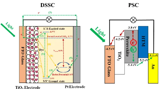
1.8.2 Structures and Operation Principles of DSSCs and PSCs
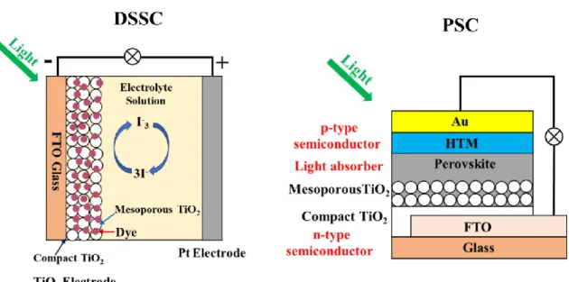
Thedye sensitized solar cells (DSSCs) mainly consists of three parts: dye sensitized
TiO2 electrode, liquid electrolyte containing redox-mediator I3-/I- and platinum electrode
with a sandwich structure, as shown in Figure 1.19.139 The dye sensitized TiO2 electrode
consists of nanoporous TiO2 film with a porosity of 50-60 sintered on the conducting glass
coated with fluorine-doped tin oxide (FTO) with a film thickness of about 10-15 um. The sensitizer dye should contain the anchoring groups such as hydroxy (-COOH) and -H2PO3
groups which can be anchored onto the TiO2 crystal surface and can absorb the light
effectively. Meanwhile, the lowest unoccupied molecular orbital (LUMO) and highest occupied molecular orbital (HOMO) of dye can match the potentials of TiO2 conduction
band and redox-mediator I3-/I-, respectively, to ensure the photoelectrons can be injected
into TiO2 and the regeneration of dye by the redox-mediator I3-. The redox I3-/I- acts as
the electron donor to regenerate the sensitizer dye from oxidized state. The platinum is used as counter electrode because of its low interface resistance for the I3-/I- redox
![Figure 2.1. Schematic illustrations of (a) [111]-faceted cubic nanocrystal and (b) crystallographic](https://thumb-ap.123doks.com/thumbv2/123deta/5737772.1020690/71.892.191.694.187.431/figure-schematic-illustrations-faceted-cubic-nanocrystal-b-crystallographic.webp)