浮体式縦軸ポンプの流力特性と循環流形成に関する研究
佐々木壮一*・徳重達也**・馬場マルティン***
A Study on the Fluid-dynamic Characteristics and the Formation of Circulating Flow of a Floating Vertical Pump
by
Soichi SASAKI*, Tatsuya TOKUSHIGE** and Martin BABA***
In order to improve the water quality environment of the stagnation waters such as the reservoirs and the dams, the floating vertical pump was developed. In this study, first of all, the influence of the setting angle of the impeller on the fluid dynamic characteristics of this pump is clarified. Moreover, the characteristics of the pump were applied as the boundary conditions to the numerical analysis on the circulating flow in a water tank.
The static pressure and the flow rate of the pump are raised up to approximately 40°according to the setting angle. The static pressure on the pressure surface side of the blade also rises at the blade tip side until 40 °; on the other hand, the pressure on the pressure surface side does not rise when the setting angle becomes more than 40°. When the angle becomes more than 40°, the domain of the low pressure of the suction pressure side has been expanded by the vortex formed to the blade tip side. It is considered that the static pressure of the pump receives the influence of the increase of the slip velocity according to the expansion of the vortex on the blade tip side. It clarified that the strong circulation can be formed with the suitable setting angle of the blade in the range of flow rate that the flow around the impeller does not separate.
Key words : Turbomachinery, Pump, Numerical Simulation, Separation, Blade
1,はじめに
浮体式縦軸ポンプは,貯水池やダムなど,静止した 水域の水質環境の改善を目的として開発された装置で ある(1).静止水域の水が縦軸の軸流型プロペラで垂直 方向へ搬送され,その水はラッパ状のダクトで表層部 へ放射状に放出される.このポンプによって水域の底 部から上昇してきた低酸素状態の水は,水面近くで空 気から酸素を取込み循環する.この結果、水中の酸素 を好む微生物が活性化され、これが汚濁原因物質を分 解する.また,このポンプによって循環流が形成され ると,水表面の紫外線によって殺菌作用が起こり,こ れが悪臭などの抑制にも効果を発揮する.このように 水質環境が実際に改善されることは,実機のフィール ド試験によっても確認されている.
このポンプによ って静止水 域の水に対 して広範 囲 に循環流を形成させるためには,軸流ポンプの流体力 学的特性と循環流形成の関係を把握することが必要に なる.しかし,実機の流体力学的特性の試験や,その 循環流形成に関する実際のフィールド試験をすること は,敷地,施設,あるいは開発コストの制約からも困 難である.このような背景から,著者らは,浮体式縦 軸ポンプによって形成される循環流を数値シミュレー ションによって再現することを試みてきた(2).これま でのポンプの分割要素を利用した流れの解析で,ポン プ近傍における実測値の速度場の傾向を数値シミュレ ーションによって表すことができることや,静止水域 の循環流の定性的な挙動を把握できることなどを示し てきた.
平成22年6月24日受理
* 機械システム工学講座(Department of Mechanical Systems Engineering)
** 生産科学研究科博士前期課程(Graduate School Student, Graduate School of Science and Technology)
*** 株式会社マサキエンベック(Masaki ENVEC Co., Ltd.)
しかし,貯水池やダムなどの実際の使用状況下では,
その水域の広さに数 10m の範囲を想定することもあ る.このような水域のモデルに対してポンプモデルを 設定し,そのポンプの流体力学的特性と循環流の流動 現象を同時に汎用計算機でシミュレーションすること は技術的に困難である.そこで本研究では,まず,軸 流ポンプ単体の流体力学的特性に及ぼす羽根取り付け 角の影響を明らかにし,羽根車の取り付け角とポンプ 設計流量の関係について考察した.また,いくつかの 羽取取り付け角における流力特性を水域での循環形成 シミュレーションに対する境界条件に利用して,その 循環流形成に及ぼす羽根取り付け角の影響を考察した.
2,おもな記号 B;羽根枚数 D;ダクト直径
D tip;羽根車直径(mm)
D hub;ハブ径(mm)
Q;流量(m3/min)
t;翼先端隙間(mm)
U;周速度(m/s)
V;絶対速度(m/s)
W;相対速度(m/s)
θ;羽根取り付け角(°)
σ;ソリディティ ψs;圧力係数 φ;流量係数 Ω;渦度(1/s)
Γ;循環(m2/s)
ν;ハブ比
3,解析モデルおよび計算方法
図1には浮体式縦軸ポンプの外観図が示されている.
このポンプには,羽根車の回転方向に応じて,正転と 逆転の2種類の運転状態がある.図中の矢印で示され るように,正転の運転では水の流れがポンプの下部よ り入り,その流れは水面に流出する.
図2には,供試羽根車の三次元モデルが示されてい る.表1は羽根車の主要寸法を整理したものである.
羽根車の外径は235mm,ハブ径は30mm,羽枚数は4 枚である.ソリディティは翼先端側から根元側まで約 1.2 となるように設計されている.実機のポンプの羽 取り付け角は28°である.この数値計算では,この羽 根取り付け角がポンプの流力特性に及ぼす影響を考察 するために,10°から50°まで5種類の羽根車の流力 特性が評価されている.
Reversed
Reversed Normal
Normal
Impeller
700 mm
Fig.1 Model of SMB30W
Hub
(a) Impeller
θ Main Flow
Hub
(b) Setting Angle on the hub
Fig.2 Model of the impeller
Table1 Main dimensions of the impeller Diameter of Impeller , Dtip(mm) 235 Diameter of Hub , Dhub(mm) 30 Setting Angle , θ (°) 10, 20, 28, 40, 50
Number of Blades , Z 4
Solidity , σ 1.2
図3は,浮体式縦軸ポンプの流力特性を評価するた めに用いられる,軸流ポンプのモデルである.表2に は,ダクトの主要寸法が示されている.ダクト直径は
245mm,翼先端すき間は5mm,ダクトの全長は1715mm
である.羽根近傍の流れに及ぼす境界条件の影響を勘 案し,ダクト直径Dを基準に,羽根車の上流側と下流 側のダクト長さがそれぞれ2Dと5Dに設定されている.
下流側から観察した羽根車の翼面が正圧面側になり,
上流側からの翼面が負圧面側になる.
数値シミュレーションの計算コードには Cradle の
SCRYU/Tetra が用いられている.浮体式縦軸ポンプ内
部の作動流体は常温(20℃)の水を想定している.ポ ンプの設計流量は100m3/hであり,実際に運転される ポンプ羽根車の定格回転数は 310rpm である.非構造
格子の要素数は約200万である(図4参照).羽根車近 傍の最小格子幅はy+ = 100程度に設定されており,こ れは汎用計算機での現実的な計算負荷に基づいて決定 されている.軸流ポンプの入口側の境界条件には全圧
一定(Pt =0)の条件が与えられており,出口側には大気
圧の条件(Ps =0)が与えられている.軸流ポンプのP-Q 特性の解析に利用される無次元量は,式(1)で定義され ている.
2 2
1 900 U Di
Q ,
2
2 U
pS
s (1)
ここで,φは流量係数,ψsは圧力係数,νはハブ比( ν
= Dhub / Dtip )である.
図5はポンプの循環特性を解析するための水槽のモ デルを示したものである.水槽の直径は32mであり,
Lin= 2D
Lout
= 5D
D
Main Flow
Main Flow Viewpoint
(a) Viewpoint for the pressure surface side
Main Flow Viewpoint
(b) Viewpoint for the Suction surface side
Fig.3 Model of the axial pump
Table2 Main dimensions of the duct for the estimation of the fluid-dynamic characteristics
1225 Outlet Length , Lout(mm)
490 Inlet Length , L in(mm)
5 Tip Clearance , t(mm)
245 Diameter , D(mm)
1225 Outlet Length , Lout(mm)
490 Inlet Length , L in(mm)
5 Tip Clearance , t(mm)
245 Diameter , D(mm)
Main Flow
A
(a) Unstructured grid around the impeller
Blade
Hub
(b) Enlargement of A
Fig.4 Mesh for the numerical simulation
Pump 32 m
2 m
Fig. 5 Schematic view of the water tank
その水深は 2mに設定されている.浮体式縦軸ポンプ の最大直径が 700mm であるので,水槽の大きさはそ の約46倍に設定されている.ポンプの入口側と出口側 の境界条件には,ポンプの流体力学的特性から決定さ れる一定流速の条件が与えられている.また,水面と 水槽の側壁にはフリースリップの条件が与えられ,水 槽の底面には壁面の境界条件が与えられている.
4,実験結果および考察
図6はポンプの流力特性を羽根取り付け角度毎に整 理したものである.実機の羽根取り付け角は28°であ り,そのときの流量は実機の試験において100m3/h(φ
=0.15)であった.図中の抵抗曲線は,この実機の運転 条件に基づいて決定 されている. 羽根取り付け角 が
10°から40°に変化すると,同一曲線上におけるポン
プ流量はその静圧の上昇に応じて増加する.しかし,
取り付け角が40°から50°に変化すると,ポンプ静圧
は上昇しなかった.
図7は取り付け角と流量係数,静圧係数の関係であ る.横軸が羽根取り付け角,縦軸が流量係数と静圧係 数である.これらは図6の抵抗曲線上の特性である.
取り付け角が10°から40°に変化すると,ポンプの流 量と静圧は増加する.一方,その角度が40°から50°
に変化したとき,その静圧は増加しなかった.これよ り,取り付け角の設計限界は40°近傍に存在すること がわかる.また,これらの関係から設計流量(φ=0.15)
を満足する羽根車の取り付け角は,25°近傍に存在す ることがわかる.
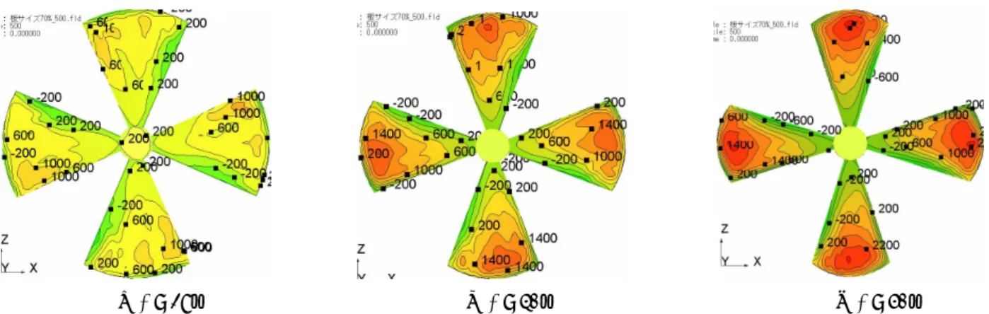
図8には,羽根車の正圧面側の圧力分布が示されて いる.羽根表面の圧力が取り付け角28°から40°にか けて上昇している.しかし,取り付け角が 40°から 50°になると,翼先端近傍での圧力の上昇量は小さい.
流れが翼に沿うときには,理論的に羽根の取り付け角 が大きくなると,その相対速度は小さくなる(図 10
0 0.1 0.2 0.3
0 0.1 0.2
φ ψs
θ = 10° θ = 20° θ = 28° θ = 40° θ = 50° N = 310 rpm
Di = 235 mm
B = 4 ψs ∝ φ2
φ = 0.15
Fig. 6 Fluid-dynamic characteristics of the pump in the different setting angle
0 10 20 30 40 50 60
0 0.1 0.2 0.3
θ , ° φ, ψs
N = 310 rpm Di = 235 mm B = 4
φ ψs
φ=0.15
Fig. 7 Relation between the setting angle and the normalized characteristic
(a) θ = 28° (b) θ = 40° (c) θ = 50°
Fig. 8 Pressure distribution on the blade surface of the pressure surface side
参照).従って,取り付け角 40°までの羽根車出口側 の静圧は,この相対速度の減速に伴うディフューザ効 果によって上昇することがわかる.図9は,負圧面側 の圧力分を示したものである.いずれの取り付け角で も,はく離渦の形成に伴う低圧の領域が翼の前縁側で 確認される.取り付け角28°の場合,羽根の先端側に 翼端渦の形成に伴う圧力分布の軌跡が確認される.取
り付け角40°と50°では,この低圧の圧力分布の軌跡
が羽根スパン中央へ広がっている.取り付け角の増大
に伴う翼端渦の拡大によって,翼後縁側の相対流れに 対して上向きの流れが生成される(図10参照).羽根 の取り付け角が40°から50°に変化したとき,このは く離流れによって生じる負圧面側のすべり速度の影響 でポンプの静圧が上昇しなかったと考えられる.
図 11 はポンプから流出した流れの速度ベクトルを 示したものである.水底側からの流れが水表面に放出 され,再びポンプへ回流する循環が形成されている.
取り付け角20°,28°および40°の循環流の形成を定 (a) θ = 28° (b) θ = 40° (c) θ = 50°
Fig. 9 Pressure distribution on the blade surface of the suction surface side
(a) θ = 28° (b) θ = 40° (c) θ = 50°
Fig. 10 Schematic view in the 2-dimensional flows on the blade
Fig. 11 Velocity vector in the water tank
N= 310 rpm D= 235 mm Re= 8.9 ×10⁵
Separated
Vortex Tip Vortex
N= 310 rpm D= 235 mm Re= 8.9 ×10⁵
Tip Vortex
N= 310 rpm D= 235 mm Re= 8.9 ×10⁵
Tip Vortex
θ
W1
W2 th
V1
Vx2
U1
Main Flow θ
W2 th
W1
V1
U1
Vx2 Main Flow
W1
V1
U1
Vx2
θ
W2 th Csl Tip Vortex
Main Flow
W2
y v z Ω u
z Ωdz dΓ
y
z ∂y
∂z 5 m
性的に比較した結果,その循環流形成の範囲について は大きな差は生じなかった (図省略) .ここで,浮体 式縦軸ポンプの半径5m以内の範囲におけるy - z断面 の循環の強さを評価する.循環は式(2)で定義される.
y v z Ω u dydz Ω
Γ x
yz x
x ,Q (2)
ここで,Ωxは渦度である.
図 12 は水平方向の微小循環の分布を取り付け角毎 に比較したものである.横軸がポンプからの距離であ り,縦軸が微小循環である.この微小循環は渦度Ωx をz方向に積分したものである.ポンプ近傍では,水 平方向に流出するせん断流の影響で,その微小循環が 大きくなっている.表3は取り付け角,流量および循 環の関係を整理したものである.羽根取り付け角が大 きくなると,ポンプの流量は静圧の上昇に伴って増加 する.また,本計算の範囲では,羽根車の取り付け角 が大きくなると,その循環は強くなった.これより,
羽根取り付け角は,水槽内の循環流の強さに影響を及 ぼすことが明らかになった.
5,おわりに
浮体式縦軸ポン プの流体力 学的特性と 水槽内の 循 環流に及ぼす羽根取り付け角の影響を明らかにするこ
とを目的として,そのポンプの流体力学的特性と外部 流動を数値シミュレーションした結果,以下の結論が 得られた.
(1) ポンプの静圧は取り付け角 40°近傍までは上昇 し,これに応じてその流量も増加する.設計流量 100m3/h を満足する羽根取り付け角は,25°近傍 に存在することがわかった.
(2) 取り付け角28°から40°では,羽根車の正圧面側 の圧力が翼先端近傍で上昇した.しかし,40°か
ら50°では,その圧力は上昇しなかった.これは,
負圧面側のはく離流れに伴うすべり速度による圧 力低下の影響であることがわかった.
(3) 羽根取り付け角が大きくなるとポンプの流量が増 加し,その流量が増えると外部流動の循環が強く なる.これより,適切な羽根取り付け角のポンプ を設計すると,外部流動に強い循環流を形成する ことができることを明らかにした.
参考文献
(1) Masaki ENVEC Co. Ltd., “Floating Water Punter – Water Beetle –”, http://www.mizusumashi.jp, (accessed 2010-5-7).
(2) Soichi SASAKI, Michio YAMASHITA, A Numerical Simulation on Underwater Convection Phenomena of a Floating Vertical Axial Pump, Reports of the Faculty of Engineering, Nagasaki University, Vol. 38, No.71 (2008), pp. 1-7
Fig.12 Distribution of the circulation element in the water tank
Table 3 Summary on the flow characteristics in the water tank
-0.30 107
40
-0.28 95
28
-0.23 82
20
Circulation, Γ(m2/s) Flow Rate , Q(m3/h)
Setting Angle , θ(°)
-0.30 107
40
-0.28 95
28
-0.23 82
20
Circulation, Γ(m2/s) Flow Rate , Q(m3/h)
Setting Angle , θ(°)
0 1 2 3 4 5
-0.1 -0.05 0
θ = 20°
θ = 28°
θ = 40°
y , m
∫Ωx dz
N = 310 rpm Di = 235 mm B = 4