Mem. School. B. O. S. T. Kinki University No. 15 : 65 ~ 74 (2005)'
Frictional Pressure Drop Characteristics of Gas-Liquid Two-Phase Flow in Small Bore Tubes
Masuo Kaji 1, Torn Sawai 1 and Tadanobu Veda 2
Abstract
65
Frictional pressure drops of horizontal and vertical air-water two-phase flows in small bore tubes were measured. Horizontal flow test sections are Pyrex glass tubes with inside diameters of around 1, 2 and 4 mm, and vertical flow test sections are stainless steel tubes with inside diameters of around 1 and 2 mm, respectively. The experimental results were compared between the horizontal and vertical flows, and good agreement was obtained for the same diameter tubes. Two-phase frictional pressure . drop multiplier
([J/
agreed well with the correlation of Chisholm and Laird at relatively large liquid and gas superficial velocities, whereas the correlation of Mishima and Hibiki for small diameter tube was valid for the case where the liquid superficial velocity was low. This depends on the Reynolds number of liquid component flow. Transition from laminar to turbulent flow was considered to occur at the liquid phase Reynolds number between 800 and 1000.1. Introduction
Pressure drop and heat transfer characteristics of gas-liquid two-phase flow in mini scale channels are important to design compact heat exchangers such as a refrigerator, an electronic device and so on.
A number of investigations have been made on hydrodynamic characteristics of two-phase flow in minichannels as reviewed by Ghiaasiaan and Abdel-Khalik(l). Experimental investigations on pressure drop and void fraction of air-water two-phase flow in circular tubes have been done by Sugawara et al.(2) , Fukano and Kariyasaki (3) , Bao et al.(4) , Mishima and Hibiki (5) and Triplett et al.(6,7). Sugawara et al. and Mishima-Hibiki found that the frictional pressure drop decreased as the tube inside diameter became small. But the pressure drop data of Fukano-Kariyasaki and Triplett et al.
gave higher values compared with the Mishima-Hibiki correlation.
The authors (8) investigated the analogy between heat transfer and fluid friction of heated air-water two-phase flow in 2 mm LD. tubes. The frictional pressure drop agreed with the Misima-Hibiki correlation at low liquid flow rate, whereas it agreed with the Chisholm-Laird(9) correlation for larger diameter tube when the liquid flow rate was large and the liquid component flow was turbulent. By using the frictional pressure drop data, the heat transfer coefficient was theoretically calculated and good agreement with the experimental results was obtained at high liquid flow rate.
The objective of this work is to experimentally investigate the frictional pressure drop of gas- liquid two-phase flow in small diameter tubes. The effects of tube wall material, flow direction and inside diameter on the frictional pressure drop characteristics of gas-liquid two-phase flow in small bore tubes are discussed. Based on the experimental data, the applicability of existing correlations is examined.
Received 15 December 2004
This study was supported by the Project Research of the School of Biology Oriented Science and Technology No. 03-IV-18, 2004.
1. Department of Mechanical Engineering and Biomimetics, Kinki University, Wakayama 649-6493, Japan
2. Graduate School of Department of Mechanical Control Engineering, Kinki University, Wakayama 649-6493, Japan
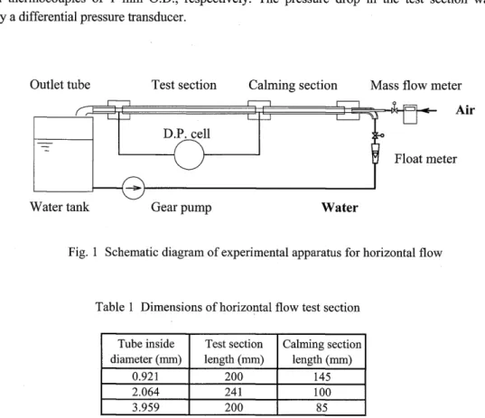
Figure 1 shows a schematic diagram of the experimental apparatus for horizontal two-phase flow.
Water is fed by a gear pump from a water tank and air is fed from a compressor to an air-water mixer.
The air-water mixer is made of a co-axial round nozzle in which air is supplied from its inner tube and water is supplied from an outer tube, respectively. The air-water mixture is introduced to the test section through a calming section made of the same material as the test section. After leaving the test section and an outlet tube, the air is released to the atmosphere and the water is circulated.
The test section is made of a Pyrex glass tube and horizontally installed. Dimensions of the test section and the calming section are shown in Table 1. The tube inside diameter is the mean value of measured inside diameters of the inlet and outlet of each test section. The test section is connected with the calming section and an outlet tube by acrylic resin joints that are carefully manufactured to have the same hole diameter.as the test section inside diameter. To measure the pressure drop in the test section, static pressure tap of an inside diameter of 0.5 mm is drilled. Smoothness of the junction was examined by measuring the frictional pressure drop of single phase water flow, and it was confirmed to agree with Hagen-Poiseulli equation for laminar flow and Blasius equation for turbulent flow.
Air flow rate was measured by a mass flow meter and water flow rate was measure by a float meter or a laminar flow meter. Temperatures of the air and water were measured upstream of the mixer by K- type sheath thermocouples of 1 mm O.D., respectively. The pressure drop in the test section was measured by a differential pressure transducer.
Outlet tube Test section Calming section Mass flow meter Air D.P. cell
Float meter
Water tank Gear pump Water
Fig. 1 Schematic diagram of experimental apparatus for horizontal flow
Table 1 Dimensions of horizontal flow test section
Tube inside Test section Calming section diameter (mm) length (mm) length (mm)
0.921 200 145
2.064 241 100
3.959 200 85
Cooling water Air
Separator Heating
test section
Air water mixer
Water
Air
67
Table 2 Dimensions of vertical flow test section Inside OJtside lbrted llfferntial pressure diarreter diarreter lerurth treaSUrel1l.l11lerurth
1.03 1.40 60 100
2.01 2.60 120 160
:amrtiCB.lS III mn
Fig. 2 Schematic diagram of experimental apparatus for vertical flow
Figure 2 shows a schematic diagram of the experimental apparatus for vertical two-phase flow.
Water is fed by a gear pump from a separator tank through a rota-meter to the test section and circulated. Air is fed from a compressor through a mass flow meter. The test section consists of an air-water mixer, a calming section, a void fraction measuring section 'and a heated section. The air- water mixer is made of a co-axial nozzle. The calming section is made of a transparent tube with the same diameter as the test section in order to observe the flow pattern. The void fraction measuring section was formed by a sandwich arrangement of five acrylic resin and four brass plates bonded together. The void fraction measurement was carried out by an electric conductance method. To make conductive the distilled water, sodium chloride (NaCl) was dissolved in about 0.04% concentration.
But the output signal from the liquid holdup probe was not affected by an alternate current for heating the stainless steel test tube.
The heated section is made of a stainless tube and heated by an alternate current. Inside diameter, wall thickness, heated length and pressure difference measurement length of the test sections are shown in Table 2. Inlet air and water, and outlet mixture temperatures are measured by K type sheath thermocouples of I mm O.D .. Outside wall temperatures of the heated test section are measured by E type thermocouples of 0.2 mm O.D. at several locations along the axis. Outlet pressure of the heated test section was measured by a Bourdon-tube gauge and pressure drop was measured by a differential pressure transducer. Heat flux was selected by a criterion that the subcooled boiling did not occur.
Figures 3 shows the measured pressure drop iJP against the superficial gas velocity} g for three test sections of the horizontal flow, respectively.}z represents the superficial liquid velocity. In these figures iJP increases as}g increases except when}z is very low. For the case of inside diameter d=0.92 mm (Fig.3(a)), iJP increases with increase in}g at lower gas flow rate, when}z is less than 0.256 mls. This is caused by the increase of volumetric flow rate by increasing the gas flow rate. Thereafter, iJP decreases as the gas flow rate increases up to a certain value, then iJP increases. From the visual observation of flow pattern, it was found that the change of pressure drop characteristics corresponded to the flow pattern transition between bubbly, plug (or slug) and annular flows. Pressure drop decrease may occur when the slip between the gas and liquid phases increases. For the cases of d=2.06 and 3.96 mm as shown in Figs. 3(b) and 3(c), data in the region where iJP increases with increase in}g at lower gas flow rate, are difficult to obtain because}g is very low.
For the vertical flow, similar relations of iJP versus}g were obtained.
~
~
~
~
T v
102 j[ mls TTT "1:·0
T 2.684 T "1"1 . 0 0 T v •• 0 •
1.681 T v . •
T T V • 00 • 0
1.148 v
•
0.673 v v
•
0 o • 0 00.256
• •
0 • 0101 0.127 0 0 a •
.·0
6.6. 0.052
•
0•
0 o 0•
o 06.6. 0 6.6. 6. 6. 6.
6. 6.
10°
10-2 10-1 10° 101 jg (mls)
(a) d=0.92 mm 102
~
101 j[ mls • • 00. 0
..
~~~ • 1.329
•
0 0 • •~
0 • • DO 6.1.056
• •
DO 6.~ 0.764
•
0 0~
o 0.474 0•
• 0 0 6. 6.10° 6. 0.163 0 6. 6.
6.
6. 6. 6.
102
j[ mls
• 1.068 o 0.821
• 0.544 o 0.285
6. 0.0996
1 0 -1 '---I.-1..L.I....L.1.I.LL.---'-.L.J....I..L.1.W.-....l-L....L.1..J..LI..LI..-.L...L...1..J...J..LW
10-2 10-1 10° 101 102 jg (mls)
(b) d=2.06 mm
10-1L--L....L..JL..U..LJL.I.L---'--L..I...L.LI.I.LI-...J...L..L.L.u..w...--,--,-,-LJ.J.llJ Fig. 3 Measured pressure drops over the test
10-2 10-1 10° 101 102 section against superficial gas velocity for jg (mls)
(c) d=3.96 mm
horizontal flow in various inside diameter tubes
69
Frictional pressure drop iJPj is calculated by subtracting the gravitational and acceleration losses in the following equation:
Mf
=
M-{(l-a)PI +apg}h-G.Gg(_l ___ l_]Pgollt Pg il1
(I)
Where, the second term of the right hand side is the gravitational loss and the third term is the acceleration loss. a is void fraction, h is the measurement length and PI, Pg are the density of liquid and gas, respectively. By assuming the homogeneous flow, the acceleration loss is evaluated from the volumetric change of the gas flow. Gg is the mass flux of gas phase, and Pgin and Pgout is the gas density at the inlet and outlet of the test section. Static pressure at the outlet of the test section is approximately the atmospheric, and the inlet static pressure is determined from the measured pressure drop. The densities Pgin and Pgouf are estimated by the both static pressures. For the horizontal flow, the gravitational loss is neglected.
For the gas-liquid two-phase flow, the frictional pressure drop is correlated by the relation between Lockhart and Martinelli parameter X and two-phase mUltiplier
f/J/
(10). X andf/J/
are defined by using the frictional pressure gradient of two-phase flow, (dp/dz)jTP' and those of gas and liquid component flows, (dp/dz)jg and (dp/dz)jl, as follows:X= (dp I dz) j1 (2)
(dp I dz) jg
2 (dp I dz ) fTP cD, = (dpl dZ)j1
(3)
Pressure gradient of gas and liquid component flows are calculated by
[dPJ
dz k-A~
2Pk(4)
The subscript k indicates the phase of liquid I or gas g. The coefficient of skin friction A is estimated by the following equations, depending on the flow is laminar or turbulent. In the gas-liquid two-phase flow, transition from laminar to turbulent is considered to occur when the Reynolds number Re becomes greater than 1000.
A = 64/Rek : Rek < 1000
A = 0.3164Rek -0.25 : Rek ~ 1000
}
(5)Lockhart and Martinelli found a relation between
f/J/
and X from experimental data of various fluids and gave a table. Chisholm and Laird (9) proposed to correlatef/J/
with Xby the following equation.(6) where C is a parameter which depends upon whether the gas and liquid component flows are laminar or turbulent, respectively. They recommended C=21 when the both component flows are turbulent.
Equation (6) with C=21 is shown by a solid line in each figure. For small diameter tubes, Mishima and Hibiki(5) measured the pressure drop of air-water two-phase flow and found that the parameter C became small as the tube diameter decreased. They proposed to modify the correlation of Chisholm and Laird by using the following parameter C.
c
= 21(1-e-0.333d)where d is the inside tube diameter in mm.
102 ... 2.684 j[ mls v 1.681
~-
•
0 1.148 0.673•
0.256101 o 0.127
~ 0.052
100~-=-~~~~~~~--~~~
10-2 10-1 100 101
j[ mls
• 1.329 o 1.056
• 0.764 o 0.474
~ 0.163
llX
(a) d=0.92 mm
100~~~~~~~~~~~~
10-2 10-1 100 101
llX
(c) d=3.96 mm
(7)
102 • 1.068 j[ mls
0 0.821
~-
•
o 0.544 0.285~ 0.0996
101
(b) d=2.06 mm
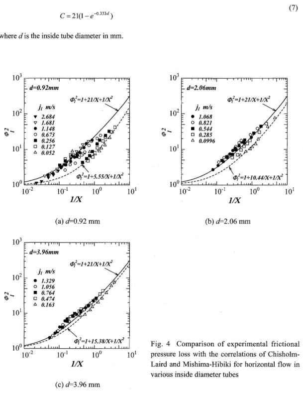
Fig. 4 Comparison of experimental frictional pressure loss with the correlations of Chisholm- Laird and Mishima-Hibiki for horizontal flow in various inside diameter tubes
71
The Mishima-Hibiki correlation is shown by a dotted line in each figure from Figs. 4(a) to 4(c).
Comparing the present experimental data with these correlations, almost the data are found to agree with Chisholm-Laird correlation at relatively high liquid flow rates. If we estimate the Reynolds number Rei of the liquid component flow, these conditions corresponds to the values of Rei larger than about 1000.
At lower liquid flow rates (Rei <1000) the present data agree with the Mishima-Hibiki correlation.
Wheni[ is low and llX is small, however, the present data give higher values compared with Mishima- Hibiki correlation, particularly, as can be seen in Fig. 4(a). In theses cases, the flow patterns are bubbly or slug flow as described above. It is considered that the frictional pressure drop characteristics of gas- liquid two-phase flow depend on the flow pattern rather than the flow condition whether the flow is laminar or turbulent, when the tube diameter is small and the gas and liquid flow rates are low.
102 j[ 'V mls 6.017
•
4.438~- o • 1.205 3.229 o 0.608
101 l::,. 0.043
100~~~~~~~~~~~~
10-2 10-1 100 101
llX
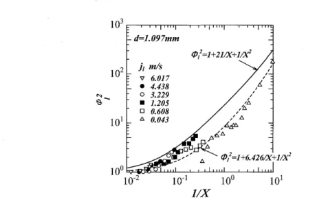
Fig. 5 Relation between
f/J/
and llXfor horizontal air-water flow experiment by Triplett et al. (7). (d=1.097 mm)Figure 5 shows the experimental results by Triplett et al. (7) with the relation between
f/J/
and llXThey carried out experiments on the air-water two-phase flow in horizontal Pyrex circular tubes with diameters d=1.097 and 1.447 mm. Only the data of d=1.097 mm tube are plotted in the figure to compare with the data shown in Fig. 4(a) (d=0.96 mm). Similar to our results,
f/J/
agrees well with the Mishima-Hibiki correlation at low liquid flow rate. But, it is not clarified whether the data agree or disagree with the Chisholm-Laird correlation at higher liquid and gas flow rates, because the number of data is insufficient.Figures 6(a) and 6(b) show the experimental results of heated air-water flows in vertical stainless steel tubes with d=1.02 and 2.01 mm, respectively. In these experiments, the heat transfer coefficient, the void fraction and the pressure drop were simultaneously measured. Flow direction was upward and the boiling did no occur. The frictional pressure drop was calculated from Eq. (1). The static head was estimated by the measured void fraction. Because the phase change due to the boiling did not occur, the acceleration loss was estimated by the change of liquid density from the inlet to the outlet of the test section, as described in Eq. (1). To consider the dependency of temperature, the physical properties, such as density and viscosity, of the fluids were evaluated by the mean temperature at the
d=1.03mm (Vertical heatedflow)
j[ m/s
• 1.874 o 1.205
• 0.796 o 0.523
b. 0.200
llX (a) d=1.03 mm
d=2.0Imm (Vertical heatedflow) (/)/=1+21IX+1IX2
• 1.12 o 0.87
• 0.57 o 0.30
b. 0.11
fo;;"
tff/i\b.
,P'~b. \
t::/
r,.,f:>
,,/Ii
,/6
, / / (/)/=1+10IX+1IX2
-_ ...
100~~~~~~~~~~~~~
10-2
(b) d=2.01 mm Fig. 6 Relation between lP/ and llXfor for heated air-water flow experiment
in vertical stainless steel tubes
inlet and outlet of the test section.
In Fig. 6(a), the experimental data atjFO.lI mls agree with the Mishima-Hibiki correlation shown by a dotted line. Whenjz becomes greater than 0.30 mis, almost the data agree with the Chisholm- Laird correlation except for a few data at jz=0.30 mls. The liquid superficial velocities of jz=O.l1 mls and 0.30 mls correspond to the liquid phase Reynolds numbers of about 300 and 800, respectively.
Although the liquid component flow is laminar considering the value of Rez, transition from laminar to turbulent may occur in the liquid flow as the gas flow rate is increased.
Making a comparison among Figs. 4 to 6 with approximately the same diameter tubes, similar results can be seen for both the horizontal flow and the vertical upward flow. The influences of the tube material, flow direction and heating on the frictional pressure drop .characteristics were not found.
4. Conclusions
In order to clarify the characteristics of frictional pressure drop in small diameter tubes, experiments were conducted on air-water two-phase flows in horizontal Pyrex glass tubes with inside diameters of about 1, 2 and 4 mm and in vertical stainless steel tubes with inside diameters of about 1 and 2 mm. The experimental data were compared with existing correlations and the applicability was investigated.
Reliability of the present data was examined by comparing with the experimental data presented by other reserchers. Results obtained are as follows:
(1) When the liquid flow rate was relatively high, the frictional pressure drop agreed well with the correlation of Chisholm and Laird. At lower liquid flow rate except for the condition of very low gas flow rate, the frictional pressure drop agreed with the correlation of Mishima and Hibiki for small diameter tube. This depends on whether the liquid component flow is laminar or turbulent, and the
73
transition from laminar to turbulent is considered to occur at the liquid phase Reynolds number between 800 and 1000.
(2) When the gas and liquid flow rates are very low, particularly, the frictional pressure drop characteristics in small diameter tube depends on the flow pattern rather than the condition whether the flow is laminar or turbulent.
(3) The experimental results of frictional pressure drop characteristics agree well between the two-phase flows in Pyrex glass horizontal tube and vertical stainless tube with the same inside tube diameter. It is found that the tube material, flow direction and heating does influence on the frictional pressure drop characteristics. Reliability of the present experimental data was confirmed by the fact that the present results of relation between
d>/
and 1 IX were similar to the experimental results of Triplett et al. (7).(4) The correlation of frictional pressure gradient should include the liquid Reynolds number as a modifying parameter to attain an accurate prediction.
5. References
(1) Ghiaasiaan, S. M., Abdel-Khalik, S. I., (2001) Two-Phase Flow in Micro-Channels, Advances in Heat Transfer, 34, Academic Press, 145-254.
(2) Sugawara, S., Katsuta, K., Ishihara, I. and Muto, T., (1967) Consideration on the pressure loss of two- phase flow in small diameter tubes, Proc. 4th National Heat Transfer Symp. of Japan, 169-172 (in Japanese).
(3) Fukano, T. and Kariyasaki, A., (1993) Characteristics of gas-liquid two-phase flow·in a capillary tube, Nuclear Engineering and Design, 141, 59-68.
(4) Bao,Z. Y., Bosnich, M. G., and Hayens, B. S., (1994) Estimation of void fraction and pressure drop for two-phase flow in fine passages, Trans. Inst. Chem. Eng., 72, 625-632.
(5) Mishima, K., Hibiki, T., (1996) Some characteristics of air-water two-phase flow in small diameter vertical tubes, Int. J Multiphase Flow, 22, 703-712.
(6) Triplett, K. A., Ghiaasiaan, S. M., Abdel-Khalik, S. I. and Sadowski, D. L., (1999) Gas-liquid two- phase flow in micro-channels, Part I: Two-phase flow pattern, Int. J. Multiphase Flow, 25, 377-394.
(7) Triplett, K. A., Ghiaasiaan, S. M., Abdel-Khalik, S. I. LeMouel, A. and McCord, B. N., (1999) Gas- liquid two-phase flow in micro-channels, Part II: Void fraction and pressure drop, Int. J Multiphase Flow, 25,395-410.
(8) Kaji, M.; Sawai, T. and Mori, K., (2003) Analogy between heat transfer and fluid friction of gas-liquid two-phase flow in minichannel, Thermal Science and Engineering, 11-6. 59-66.
(9) Chisholm, D. and Laird, A. D. K., Two-Phase Flow in Rough Tubes, Trans. ASME, 80,276-286 (1958).
(10) Lockhart, R. W. and Martinelli, R. C., (1949) Proposed correlation of data for isothermal two-phase, two-component flow in pipes, Chem. Eng. Prog., 5, 39-48.
*,OO1f
~ ~¥TrEn Q
~5(\, - 71< =:t§ ¥TrE
0) ~~EEjJ m~!pij'''t1 0)iJ!U AE
~~ ~iT v '\,
~ 1~ 0):*:
V \1f
~;:M T Q
Chisholm-LairdO):t§ M:rt, *,OO1f
~;:MTQ
Mishima-HibikiO):t§ M:rt
~ .I:t~ • 1~~iL
t~o ~~~'i~1~~1, 2, 4rumO)/'~-{V/'~Ajj7A1f~{!:t~5:\1f~Lt~*F1JO~71<I!L¥TrE,
JOJ:u,
~1~*'1 1,
2rum
O)A T ~ vAi~1f~1*~5:\1f ~ Lt~1Jo~A~IlLI:.~¥TrE~;:'0v\--C~jjlliLko
71<I!L¥TrE~~'i~EEO)Jj.O)iJ!UAE~iT"0 t~iJ~, ~@Ll:~¥TrE~~'im5(\,::1 ~
7'"
~7'
~ A¥t~;:J:
~ ~-{F¥ t
[RJa~~AEL,&.m~O)~~~fi"0--C~~EEjJm~~.WLko
~1~iJ~~
Lv
\1f~;:MT Q5(\,?11Z=:t§¥TrEO)~~EEjJm~tr~lt1~'i,71<I!L¥TrE
~ ~jILl:~¥TrE~;:'0 v \--C
O)~~~*iJql~~f-!SeTQ:' ~
iJ)G,
1f:t;jW~¥TrEtbjJrPJO)~.~st~tftv\:, ~ iJ~~ GiJ)~ ft"0 t~o ~
G
~;:, ~~EEjJm~¥f't1~'i?11Z¥TrE:5:~;:*~< 13X1f L,
?11Z¥TrE:5:iJ~*~< ?11Z
v-{ / !VA'*y:iJ)GEL¥TrE~*Ij~~nQ~B'~'i, tf::~I3"J~1~0):*:v\1f~;:~tL
--cJim
~nQ Chisholm-Laird O):rt~;:-!SeT Q
iJ~,?11Z¥TrE.£
~iijGy ~ it Q~;: '0n~~EEjJm~~'i{Xm~;:1fS:TL
--Cv \< :.
~ iJ~~G iJ)
~ ft"0t~o ?11Z¥TrE:5:iJ~ti60--C!J\~<, ?11Zv-{ /
!VA'*y:iJ)G)j¥TrE~*Ij~~nQ~~:t~~~'i, ~~EEjJ t~~¥f't1~'i*,OO1f ~;:MTQ
Mishima-HibikiO):rt
~J: < -!SeT Q :.
~ iJ~*Ij"0 t~o Mishima-Hibiki 0):rt~'i1f~1~0)Jj.~/~7;'