PhD Dissertation
Experimental and Numerical Investigations on the Hydraulic Characteristics of Two-phase Flow in Rock Fractures
岩盤き裂内における二相流の水理学的特性に 関する数値と実験的研究
2019
年3
月長崎大学大学院工学研究科
王 辰
Chen Wang
Experimental and Numerical Investigations on the Hydraulic Characteristics of Two-phase Flow in Rock Fractures
I
Acknowledgements
I would like to express my appreciation to all those who offer their kind help during my stay in Nagasaki University. It’s difficult to list all of them, but I’d like to appreciate everyone who has contributions to my research and life.
I will forever be grateful for the guidance from my supervisor—Professor Yujing Jiang, not only because he guided my studies, but also for the sustained support and encouragement on me which has provided me with the confidence in continuing this PhD program. The skills I learned from my professor are not only useful to the PhD studies, but also bring benefits to my lifetime.
My thanks also go to Professor Akihide Tada and Professor Kiyoshi Omine, who offered their kind suggestions to make this work better.
Assistant Professor Satoshi Sugimoto is appreciated for his kind help in preparing the experiments. In addition, I especially appreciate the sincere help from Professor Bo Li, who has offered valuable proposals to my work, especially in the period when I was confused about the research.
My fellows in Nagasaki are appreciated for their contributions to both my study and life. Thanks for the care from my tutor Dr. Xiao Shi and my senior Dr. Xiaoshan Wang, especially in the period I fell ill in 2016. Thanks for the kindness of Mr. Xuepeng Zhang from entrance to the university to graduation from here. Many thanks to Mr. Changsheng Wang and Mr. Jiankang Liu for their support in my experiment.
Before I came to Japan, Professor Yaodong Jiang, my supervisor of master course, has encouraged me to apply for this overseas study, for which I express my sincere gratitude.
Finally, I’d like to express my gratitude to my parents and brothers for their dedicated love.
II
III
Abstract
Multiphase flow is an important research task in many engineering applications, including the exploitation of conventional gas and oil resources, coalbed methane recovery, CO2
sequestration and the exploitation of geothermal energy. Two-phase flow is the basis for understanding the multiphase flow. Two-phase flow in porous media or rock fractures tend to be investigated with seepage theories, while analysis on the two-phase flow are very dependent on the experimental equations. Experimental equations that are applicable to one kind of fracture may have significant deviations on the other fracture. In other words, a general model for describing two-phase flow in the fracture is still absent. This research is aimed at expanding the results on the hydraulic behavior of two-phase flow and making a further step to establish general equations. It investigated the hydraulic characteristics of two-phase flow in rock fractures with both experiments and numerical simulation. It is composed of two aspects: two phase flow in the single fracture and two- phase flow in the intersecting fractures, which aims at forming the basis for studying the two-phase flow in the fracture network.
In Chapter 1, the two-phase flow phenomena in rock fractures in the coalbed methane recovery and geothermal energy development are introduced, and the purposes and contents of this dissertation are introduced.
In Chapter 2, the current research status and previous researches on two-phase flow in pipes, porous media and fractures are list. Different research approaches are compared and analyzed, and the corresponding enlightenment on this research is also list.
In the Chapter 3, an experiment system developed for two-phase flow test is introduced.
The experiment system is composed of the fluid supplying subsystem, the two-phase flow box and the measurement subsystem. The two-phase flow box is the core element in this system, which can seal up the rock specimens without using glue. With this experiment system, two-phase flow experiments were conducted in the single rock fractures. The results show that the flow structures in a rough fracture show more similarity to that of two-phase flow in porous media, while the flow structures in a smooth fracture were similar to that in pipes. In the rough fracture, both water and gas tend to flow in their own channels, and the flow channels are stable. The relative permeability approximately follows the Corey model, but there are some deviations, and the deviation increases with respect to the increase of water flow velocity. This is to say, the relative permeability is not only the function of saturation, but also the function of water flow velocities. The deviation from Corey model indicates that the inertial effect of water decreases the relative permeability and increases the two-phase interference. The Lockhart-Martinelli model can also fit the results well. The increase of water flow rate leads to the increase of flow turbulence, which also increases the flow interference between two phases.
In Chapter 4, a 2D numerical model of two-phase flow in the single rock fracture was established for investigating the role of fracture morphology on the two-phase pressure drop. As indicated by the experiment results, the pressure drop of two-phase flow in the single rock fracture is influenced by multiple factors. In order to quantify the role of one
IV
factor—the fracture morphology, a 2D numerical model was established with the level set method. The simulation is conducted in a series of rough fractures, which have a normal distribution in the fracture aperture but with different standard deviations. The simulation results show that the flow structures are correlated with the fracture morphology. With the increase of the standard deviation, the flow structure becomes more tortuous. The relative permeability is also influenced by the standard deviation of the fracture aperture. This is induced by two reasons: the tortuosity degree of the flow channels and the different effects of the capillary pressure. The flow tortuosity is influenced by the aperture distribution; the larger the standard deviation, the more tortuous the flow channels will be; while the influence of capillary pressure also increases with respect to the roughness of the fracture. In addition, the impact of capillary pressure differs in different flow patterns due to the different quantities of phase interfaces. The effect of capillary pressure is more significant in bubble flow than in continuous flow.
The simulation results show that the relative permeabilities of both phases are not only the function of saturation, but also the function of flow velocities and the aperture distributions (especially standard deviations).
In Chapters 5 and 6, a series of gas-water two-phase flow experiments were conducted in both the 3D intersecting fracture model and 2D intersecting fracture models. The results of experiments in the smooth 3D intersecting fracture indicate that the flow structures show more similarity to that of stratified wavy flow in pipes. The nonlinearity induced by the inertial force and turbulence in the intersecting fractures cannot be neglected. The two-phase pressure drop increases nonlinearly with respect to the gas flow rate, which is induced by the strong inertial effect in the intersecting fracture. The Martinelli-Lockhart model is no only effective for describing the two-phase flow in the single fracture, but also effective for the intersecting fractures. The phase distribution behavior at the fracture intersection was studied with the 2D models with intersecting fractures. The results show that with the increase of gas injection rates, the evolution of water and gas distribution can be classified into three stages. In different stages, the dominant factors differed. In the first stage, gas flowed as bubbles and the flow of gas bubbles was stable; gas distribution was dominated by the gas injection position; in the second stage, gas flow as larger bubbles and the phase distribution of water and gas was dominated by the difference of the inertial effect of the two phases; in the third stage, the turbulence became serious and gas flowed as slugs. The inertial effect still influenced the phase distribution, but it is no longer the dominate factor. The inertial effect tended to separate the two phases, but the turbulence tended to homogenize the phase distribution.
In Chapter 7, the conclusions in each chapter are summarized and the enlightenment on future studies are given.
Keywords: two-phase flow, rock fracture, intersecting fracture, visualized experiment, relative permeability, Lockhart-Martinelli multiplier, flow structures, level set method, phase distribution
V
要 旨
混相流は炭層ガスの開発、天然ガスと石油の利用、地熱開発、二酸化炭素の 貯留などの工事の中で発生する。混相流の行為を理解するため、二相流の知識 は基礎である。岩盤き裂における二相流は一般的に多孔質材料の流体力学に基 づいて研究されている。今岩盤における二相流の解析には実験式に依存する点 が多い。いずれの実験式はあるき裂の実験データに適用しますが、他のき裂に 対して誤差が大きくなる傾向がある。つまり、一般形の式はまだない。本研究 はき裂における二相流の挙動に関する研究結果を拡充するため、実験とシミュ レーションで岩盤き裂の水理学的特性を解明することです。本研究には「単一 き裂における二相流」と「交差き裂における二相流」という二種類の内容があ る。
第一章では、炭層ガスと地熱の開発に伴う岩盤き裂における二相流現象を紹 介した。その上に、本研究の目的と構成を示した。
第二章では、管内、多孔質材料とき裂における二相流に関する研究現状と既 往研究について記述し,各種の研究方法を分析した上に、本研究に与えたヒン トを示した。
第三章では、単一き裂の二相流実験システムを紹介した。この実験システム は液体供給設備、気体供給設備、二相流ボックスと測定設備により構成される。
二相流ボックスはコアな設備であるので、接着剤を使わないながら岩盤供試体 を密封できる。この実験システムを使って単一き裂の気液二相流実験を行った。
実験結果により、滑らかき裂における二相流の流動様式は管内における二相流 の流動様式と似ていましたが、粗いき裂における二相流の流動様式は多孔質材 料における二相流の流動様式と似ていた。粗いき裂における二相流は、液相と 気相両方も自分の流路に流れていたので、流路が安定である。相対浸透率は大
体に Corey モデルに合いますけど、すこし偏差がある。その偏差は水流速度の
増加に対して増加する。相対浸透率は飽和度の関数だけではなく、水流速度の 関数でもある。水の慣性は相対浸透率を減少させ、二相間の干渉を増加させる。
実験結果もLockhart-Martinelliモデルに合う。水流速度の増加は乱流の程度を増 加させるので、それも二相間の干渉を増加させる。
第三章の実験結果により、二相流の水力的特徴は複数の要因に影響される。
実験で単一の要因を解析することが難しいである。従って、単一き裂面の形態
VI
が二相流水理的特性に与える影響を解明するため、第四章では等位集合方法
(Level set method)で二次元シミュレーションモデルを立てた。このシミュレ ーションは一連の生成したき裂面に行われた。これらのき裂面の開口幅は正規 分布に従いますけど、開口幅平均値と分散の値が異なる。シミュレーションの 結果より、二相流の流動様式はき裂面の形態と相関する。分散値の増加に伴い、
流動様式はより曲がりくねっている。相対浸透率も正規分布の分散値に影響さ れる;これは二つの要因によって引き起こされる:一つが流路の屈曲度、もう 一つが毛管圧である。正規分布の分散値の増加に伴い、流路の屈曲度が増加す るので、流動中の圧力損失と相対浸透率を高める。また、き裂面の粗さの増加 に伴い、毛管圧の影響も増加する。この毛管圧より発生した抵抗力が相対浸透 率を減少する。また、二相間の界面の量が異なるため、異なる流動様式に毛管 圧の影響は異なる。連続流により、気泡流における毛管圧の影響が大きいであ る。総じて言えば、シミュレーションの結果により、相対浸透率は飽和度の関 数だけではなく、水流速度とき裂開口分布(特に分散値)の関数でもある。
第五章と第六章では、二次元交差き裂と三次元交差き裂における気液二相 流実験を行った。三次元交差き裂の二相流実験結果により、滑らかな交差き裂 における二相流の流動様式はパイプにおける成層二相流の流動様式と似ている。
慣性力と乱流によって誘起される非線形性が無視できない。き裂交差点によっ て誘起された慣性力により、気体流量の増加に対して圧力損失が非線形的に増 加する。交差き裂に対してMartinelli-Lockhartモデルは有効である。二次元交差 き裂で相の分配の特徴を研究した。実験結果により、気体注入速度に伴い、水 と気体の分配は 3 段階に分ける。異なる段階で分配を支配する要因が異なる。
第一段階では、気体は気泡として安定的に流れていた;気体の分配は気体注入 位置に支配された。第二段階では、気泡のサイズが大きくなって、気体と水の 分配は二相間の慣性力の差に支配された。第三段階では、気体はスラグ流とし て流れていたので、乱流の程度も上がった。水と気体の分配は慣性力に影響さ れますけど、慣性力は唯一の要因ではない。慣性力は二つ流体を分離する傾向 がありますけど、乱流は二つ流体の分配を均一化する傾向がある。
第七章では、各章の成果を総括して結論とした;その上に、未来研究の考え をしめした。
キ ーワード : 二 相 流 、 岩 盤 き 裂 、 交 差 き 裂 、 可 視 化 実 験 、 相 対 浸 透 率、
Lockhart-Martinelli 乗数、流動様式、等位集合方法、相分布
VII
Contents
Chapter 1 Introduction ... 1
1.1 Background ... 1
1.2 Outline of the dissertation ... 5
Chapter 2 Reviews on the studies of two-phase flow ... 7
2.1 Approaches of two-phase flow in pipes ... 7
2.1.1 Homogenous model and the friction factor ... 8
2.1.2 Lockhart-Martinelli model and the multipliers ... 9
2.2 Approaches of two-phase flow in porous media... 10
2.2.1 Extended Darcy’s law and relative permeability ... 10
2.2.2 Models for relative permeability ... 11
2.3 Typical studies on two-phase flow in the rock fracture ... 13
2.3.1 Studies that conform to X-model, viscous coupling model, Corey model .... 14
2.3.2 Studies that shows stronger interference than Corey model ... 14
2.3.3 Studies with novel models of relative permeability ... 15
2.3.4 Studies with models of two-phase flow in conduit ... 15
2.4 Motivations of this research ... 16
Chapter 3 Development of an experiment system and experimental studies on the hydraulic characteristics of two-phase flow in the single rock fractures ... 18
3.1 Development of an experiment system ... 18
3.1.1 Reviews on experiment systems for two-phase flow ... 18
3.1.2 The experiment system ... 20
3.1.3 Two-phase flow box ... 23
3.1.4 Measurement techniques ... 28
3.2 Two-phase flow experiment in the single rock fracture ... 29
3.2.1 The testing procedures ... 29
3.2.2 Calculation of the hydraulic aperture and intrinsic permeability ... 32
3.2.3 Calculation of the relative permeability and phase multipliers ... 33
3.3 The testing results ... 34
3.3.1 Evolution of the flow structures ... 34
3.3.2 Evolution of the relative permeability ... 41
3.3.3 Evolution of the phase multipliers ... 43
3.4 Summary ... 45
Chapter 4 Numerical investigation on the two-phase flow in single rock fractures: the effect of capillary pressure and fracture morphology... 47
VIII
4.1 Introduction of level set method in two-phase flow simulation ... 47
4.1.1 Introduction of the level set method ... 47
4.1.2 Derivation of the 2D model of level set method ... 49
4.2 Model description ... 52
4.2.1 Geometry and boundary conditions ... 52
4.2.2 The randomly rough surface generated with the spatial-frequency series ... 53
4.3 Evolution of the flow structures and relative permeability ... 55
4.3.1 The role of capillary pressure on the two-phase flow ... 55
4.3.2 Quantification of the evolution of saturation and relative permeability ... 62
4.3.3 The evolution of flow structures in normal distribution fractures ... 66
4.4 Summary ... 73
Chapter 5 Experimental study on the two-phase hydraulic properties in the intersecting fracture ... 74
5.1 Introduction ... 74
5.2 Experiment in the intersecting fractures ... 76
5.2.1 Experiment system ... 76
5.2.2 Experiment procedures ... 78
5.3 Potential models for describing two-phase flow in the intersecting fractures ... 79
5.4 Hydraulic characteristics of two-phase flow in the intersecting fractures ... 80
5.4.1 Results of single-phase flow test ... 80
5.4.2 Hydraulic characteristics of the two-phase flow in the intersecting fractures 81 5.5 Summary ... 95
Chapter 6 Experimental investigation on the phase distribution characteristics of gas and water in the intersecting fracture ... 96
6.1 Introduction ... 96
6.2 Experimental study on the distribution of two phases ... 98
6.2.1 Experimental system ... 98
6.2.2 The testing procedures ... 100
6.3 Quantification of the phase distribution ... 101
6.3.1 The effect of gas injection rate ... 101
6.3.2 The effect of water injection rate and fracture intersecting angle ... 108
6.4 Summary ... 112
Chapter 7 Conclusions and Future Work ... 114
7.1 Conclusions ... 114
7.2 Recommended future studies ... 116
References ... 117
1
Chapter 1 Introduction
1.1 Background
Multiphase flow refers the simultaneous flow of materials with two or more immiscible phases (gas, liquid, solid), or materials with different properties but in the same phase (i.e.
liquid-liquid systems) [Wang, 2012]. Multiphase flow exists in many engineering applications, such as the gas-oil exploitation, gas-oil storage and transportation, chemical engineering, coalbed methane recovery, CO2 sequestration, contaminant transport and the exploitation of geothermal energy [Kimura, 1997; Detwiler et al., 2009; Persoff and Pruess, 1995; Sudicky and Frind, 1982; Nuske et al., 2010]. Two-phase flow is the basis for studying multiphase flow. Studies on two-phase flow can be classified into two categories: (1) Two-phase flow in pipes. In the gas-oil transportation and chemical engineering, the two-phase flow dynamics in different kinds of conduit is a critical concern, because two-phase flow shows different pressure drop characteristics from that of single-phase flow. These issues are studied with the conduit flow models and conventional theories of fluid mechanics. (2) Two-phase flow in porous media or fractures.
In oil-gas recovery and coalbed methane recovery, the issues concerning two-phase flow in porous media and fractures tend to be investigated with seepage theories.
In this dissertation, the two-phase flow in fractures is investigated, which concerns the applications such as coalbed methane recovery, CO2 sequestration and geothermal energy exploitation.
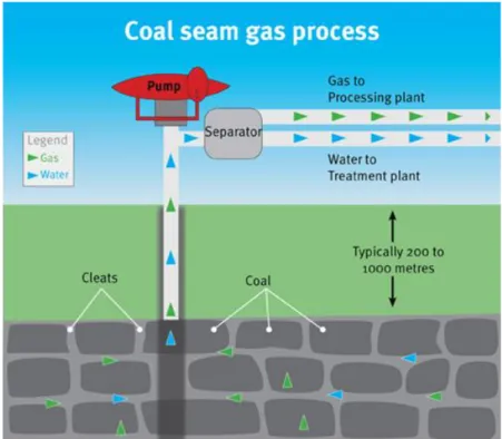
Coalbed methane is one of the extensively utilized unconventional gases, which has decreased the utilization of coal. Consequently, it is assumed as an environmentally friendly resource. More than 90% coalbed methane is stored as absorbed state in the coal seams. With the depletion of reservoir pressure, the absorbed gas changes into gaseous phase. That is to say, the exploitation of coalbed methane is accompanied with a process of gas desorption. In addition, the coal seams are initially abounded with water. The recovery of coalbed methane resources is composed of three stages [Feng, 2009]. In the first stage, water is drained out from the coal seams, which is a single-phase flow process.
With the depletion of the reservoir pressure, gas in the absorbed phase begins to desorb from the coal matrix. Due to its small quantity, the gas phase is discontinuous and bubbly
2
Fig. 1-1 The schematic of gas and water extraction from coal seams
flow is formed. The water and gas transport in the fractures of coal seams and the conduit of the extraction well, and they will be separated by a separator, as shown in Fig.1-1. With more gas desorbing, the gas percentage increases and the flow structures may change. In the third stage, the water depletes, and gas keeps transporting, namely the recovery process returns to a single-phase flow; but the trapped water phase may have a significant influence on the transport of gas. In the above-mentioned process, there is a transition from single-phase flow to two-phase flow in the fracture network, and the gas desorption rate varies with respect to time. Consequently, a two-phase flow with different gas-water ratios will be formed. Since the two-phase flow process influences the production rate, the water drainage rate and gas exploitation rate must be well controlled to reach an optimal recovery ratio.
CO2 sequestration is an effective method to reduce the CO2 emission amount into the atmosphere. The injection of CO2 into the saline aquifers or abandoned coal seams will lead to a two-phase flow of CO2 and saline water [Soong et al., 2004]. The injection of CO2 into the coal seams can increase the output of coalbed methane. The injected CO2
can be in gaseous, supercritical or liquid state. Consequently, different kinds of multiphase-phase flow can be formed, namely supercritical CO2-water, gaseous CO2-
3
water or even three-phase flow of supercritical CO2-gaseous CO2-water. The relative permeability of CO2 and brine has an obvious impact on the transport of both phases and the injection efficiency. The relative permeability is influenced by many factors, for example, the increase of the viscosity ratio between the fluid pairs will make the more mobile phase (less viscous) to flow through the pore space [Bachu and Bennion, 2008].
The stability of CO2 in the aquifers should be carefully evaluated to avoid the escape of CO2, so before CO2 becomes fixed through chemical reactions with the saline water, the transport of multiple phases shall be fully estimated, which requires a profound understanding of the transport mechanisms of multiphases in the fracture network or saline aquifers or coal seams.
Fig. 1-2. The schematic of geothermal power plant [Kimura, 1997]
4
Geothermal energy is an environmentally friendly reproducible resource. Conventional method of utilizing the geothermal energy includes two steps: (1) injecting water into the rock strata through the fracture network, where steam will be produced due to the high temperature; (2) extracting the high-temperature steam and water into the earth surface to generate electricity. Because the average temperature gradient in the earth's crust is about 30 °C/km, an excavation of 10 km into the earth will provide access to the heat source of 300 °C, where the water will be in the state of steam [Kimura, 1997]. This is to say, a two-phase flow of water in liquid state and gaseous state exists in the rock fractures and the production well, as shown in Fig. 1-2. The two phases, namely water and vapor, are separated in a separator. The vapor is used for generating electricity, and the water is injected back to the underground strata. The purpose of injecting water back to the underground is to prevent it polluting the environment since the extracted water is generally brine. However, this two-phase flow process is different from the above- mentioned two-phase flow in coalbed methane recovery or oil-gas exploitation, because liquid water and steam can convert into each other according to the temperature, namely there is a phase change process along with the transport of two phases. In this process, the decrease of the two-phase pressure in the production well and the evolution of temperature are coupled with each other, which requires to be fully understood for providing basis for the design of the production well.
Compared with single-phase flow, the hydraulic characteristics of two-phase flow is influenced by more factors, including the capillary pressure, the viscous coupling and additional turbulence induced by two-phase interactions. Due to the complexity of the influencing factors, there is still not a general equation which can predict two-phase flow characteristics in all kinds of circumstances. In addition, it is also difficult for two-phase simulation to cover all the factors which influence the flow. In view of this, this dissertation has three aims: (1) To investigate the hydraulic characteristics of single fractures with experiments, and evaluate the effect of surface morphology on two-phase relative permeability and Lockhart- Martinelli multipliers; (2) To quantitatively evaluate the impact of aperture distribution on the two-phase flow concerning the effect of capillary pressure with simulation; (3) To study the applicability of Lockhart-Martinelli model in intersecting fractures with experiments. Based on the above-mentioned researches, we expect to provide a basis on studying the hydraulic characteristics of two-
5
phase flow in the fracture network.
1.2 Outline of the dissertation
This dissertation is divided into 7 chapters. Chapter 1 and Chapter 2 give a review on this research theme. Chapter 3 and Chapter 4 study the hydraulic characteristics of two-phase flow in single fractures, with experiment and simulation respectively. Though the experiment includes more pressure-drop mechanisms than the simulation, Chapter 4
Fig. 1-3 Dissertation structure Numerical study
on the role of capillary pressure
Hydraulic Characteristics of Two-phase Flow in Fractures
Two-phase flow in single fractures
Experimental study on the hydraulic characteristics
Experimental study on the hydraulic characteristics
Experimental study on the phase distribution
Two-phase flow in the intersecting fractures Development of an
experiment system
Generation of random fracture Numerical simulation with level set method Obtain the flow
structures, pressure drop characteristics
Quantification of the distribution behavior in 2D intersecting fractures
Quantification of the hydraulic properties of 3D intersecting fractures
Quantification of the effect of fracture morphology
Determine the dominant factors governing the two-phase flow
Form the basis of establishing a general method for two-phase flow in fracture network
Chapter 3 Chapter 4 Chapter 5 Chapter 6
6
provides reference with quantitative analysis on the effect of capillary pressure. Chapter 5 and Chapter 6 investigate the two-phase flow hydraulic characteristics and distribution behavior, respectively. They are outlined as the following:
Chapter 1 introduces the engineering applications of two-phase flow in fractures and states the significance of the research.
Chapter 2 lists the theoretical and empirical models for two-phase flow in conduit, porous media and fractures. Most of the approaches in two-phase flow are covered here.
Many of them are derived from the experiments, and the derivations are also simply introduced.
Chapter 3 firstly introduces the experimental apparatus developed by the author; the core part—two-phase flow box and the corresponding sealing techniques are introduced in detail. Then the experiment procedures, results of tests in two different fractures are list. The effect of the fracture surface morphology on the relative permeability and phase multipliers is discussed.
Chapter 4 introduces a two-dimensional numerical model for simulating two-phase flow in a single fracture with the level set method. The effect of capillary pressure and fracture aperture distribution on the relative permeability is discussed.
Chapter 5 introduces the experimental apparatus and procedures of two-phase flow tests in intersecting fractures. The applicability of the method in single fractures (Lockhart-Martinelli multipliers) in intersecting fracture is investigated. Furthermore, the influence of fracture intersections on the Lockhart-Martinelli multipliers is also discussed.
Chapter 6 investigates the two-phase flow distribution behavior in intersecting fractures by experiments. The inertial effect, intersecting angle on the distribution characteristics are analyzed.
Chapter 7 lists the conclusions. In addition, future numerical and experimental researches are recommended.
7
Chapter 2 Reviews on the studies of two-phase flow
Studies on two-phase flow can be divided into three types: (1) Two-phase flow in pipes, which refers to the two-phase flow in large-scale tubes, such as the gas-oil transportation conduit. This kind of studies are conducted on the basis of the conventional theories of fluid mechanics. (2) Two-phase flow in porous media, such as the gas-water two-phase flow in the matrix of coal seams. This kind of studies are based on the theory of poromechanics. (3) Two-phase flow in the fractures, such as the gas-water two-phase flow in the fractures of coal seams, CO2-water two-phase flow in the fractures of saline aquifers.
Under many circumstances, the flow in fractures exists together with that in porous media since many porous media are abundant of fracture network.
In this dissertation, we investigate the two-phase flow in fractures. The studies of two- phase flow in the fractures mainly borrow the methods of two-phase flow in porous media, namely poromechanics, since they show much similarity to each other [Fourar and Lenormand, 1998; Brooks and Corey, 1964]. But some researchers also tried to use the theories in conduit flow, and they found some correlations between the flow regime and the pressure drop characteristics [Fourar and Bories, 1993]. To illustrate the relationship between different approaches, a systematical introduction is given in the following sections. This helps understand the origins of different research methods that are used in investigating two-phase flow in fractures.
2.1 Approaches of two-phase flow in pipes
As mentioned above, two-phase flow in conduit are studied on the basis of conventional fluid mechanics, that is to say, the fundamental mass conservation equations and momentum conservation equations shall be established for the fluids. However, compared with single-phase flow, more difficulties or complexities remain in the two- phase problems remain, as indicated in the following aspects: (1) Besides the conservation equations and momentum equations, additional equations also require to be established, such as the interactions between two phases (mass transfer, energy transfer);
(2) Much of the energy transfer occurs at the two-phase interfaces, however, the interfaces are always moving, which adds to the difficulty of calculation. (3) The distribution of two phases can be of different forms. Suppose a gas-water two-phase flow in which the gas
8
and water accounts for 50%, respectively, the distribution of two phases can be the even distribution of gas bubbles in water, or both gas and water flow continuously in their respective channels, which is knows as stratified flow. This is called as flow structure.
Difference in flow structures leads to different mechanical (pressure drop of flow) performance, mass transfer performance and heat transfer performance.
Due to the above-mentioned complexities, until now there is still not a general equation that can cover all kinds of two-phase flow issues. Taking the problem of moving interface as an example, some methods track the two-phase interface to accurately estimate the interactions between two phases, such level set method, phase field method, and VOF method. In the future, it may be possible to code the Navier-Stokes equations for each of phases and compute every detail of a multiphase flow and the position of every interface [Brennen, 2005]. This will lead to very accurate calculation results. But this kind of calculation is far beyond the capacity of present computers. Consequently, macroscopic calculation models, which are more applicable to compute large-scale two-phase flow problems, should be established. In this section, some typical methods are list as the following.
Fig. 2-1 Flow structures—bubble flow, stratified flow, droplet flow
2.1.1 Homogenous model and the friction factor
Homogenous model is a simple method for the calculation of two-phase conduit flow. In this method, two-phase flow is treated as single-phase flow by homogenizing the parameters of two phases into that of a hypothetical single-phase. In this “sing-phase flow”, all the critical variables and parameters are the average of the original two phases.
The flow of this “single-phase” fluid is assumed to follow the rules of classical fluid mechanics, therefore, the two-phase flow can be calculated with the sing-phase fluid mechanics. The density of the two-phase mixture is defined as Equation 2-1, in which ρ,
9
ρα, ρβ are the density of the mixture, density of phase α and density of phase β, respectively.
qα, qβare the flow rate of phase α and phase β, respectively.
q q
q q
= +
+ (2-1) The viscosity of the two-phase mixture is defined as Equation 2-2, in which μ, μα, μβ
are the viscosity of the mixture, phase α and phase β, respectively. χ is the mass fraction factor, which is defined as Mα/ Mα+Mβ, Mis the mass flow rate.
q q
q q
= +
+ (2-2) The two-phase Reynolds number is defined as Equation 2-3, in which h is half of the hydraulic diameter, in which V is the velocity of the mixture, defined as (qα+qβ)/A, where A is the area of the cross section. The two-phase pressure gradient is derived as Equation 2-4 (with the acceleration components neglected), in which the Cf is the friction factor, d is the hydraulic diameter. The homogeneous model aims to seek for the correlation between Cf and Re2. With an appropriately established correlation [Fourar and Bories, 1993], the pressure drop of two-phase flow can be predicted.
2
Re 2hV
= (2-3)
2
2 f
dp V
dx = C d (2-4) 2.1.2 Lockhart-Martinelli model and the multipliers
Lockhart-Martinelli model is derived by accounting for the property that the two-phase pressure drop is always than that of single-phase pressure drop with the same flow rate.
Two critical parameters are defined to evaluate this property, as indicated in Equations 2- 5 and 2-6. Here, φL is the liquid multiplier. It is defined as the square root of the ratio between the two-phase pressure drop (dp/dx) and the single-phase pressure drop of the liquid (dp/dx)L. φG is the gas multiplier, which is defined as the square root of the ratio between the two-phase pressure drop (dp/dx) and the single-phase pressure drop of the gas (dp/dx)G.
10
/
( / )
L
L
dp dx dp dx
= (2-5) /
( / )
G
G
dp dx dp dx
= (2-6) These definitions are similar to that of relative permeabilities (as will be illustrated in Section 2.2), which are defined as the ratio between the two-phase permeability and the single-phase permeability. Both the multiplier and the relative permeability are the ratio between the two-phase transport capacity and the single-phase transport capacity.
However, the difference lies in that the multipliers in Lockhart-Martinelli model accounts for the inertial effect. This is because in calculating the single-phase pressure drop (dp/dx)L and (dp/dx)G, the inertial effect is accounted for by using the Forchheimer’s law.
A suitable model which can describe the evolution of Lockhart-Martinelli multipliers can be used to model the two-phase flow, especially for calculating the pressure drop. This will be introduced in Chapter 5 in detail.
2.2 Approaches of two-phase flow in porous media 2.2.1 Extended Darcy’s law and relative permeability
The main difference between the two-phase flow in porous media and the single-phase flow in porous media is that: the permeability of single-phase flow a constant and it is considered as a property of the porous medium itself [Brooks and Corey, 1964]; but the effective permeability of two-phase flow is not only influenced by the property of the porous medium, but also the properties of both fluids and the interactions between them.
This difference gives enlightenment about the approaches of studying two-phase flow in porous media: to extend the equations of single-phase flow by considering the two-phase interactions, and to extend the effective permeability as the function of the property of the medium and the interactions between two phases. The most commonly adopted alternative is to extend the Darcy’s law.
Darcy’s law is the basis of hydrogeology, which is formulated by Henry Darcy, a French engineer, from the experiments on the flow of water through beds of sand. It is also derived theoretically from the Navier-Stokes equations via homogenization [Whitaker, 1986]. This law indicates a linear correlation between the pressure drop and the superficial velocity of water fluid in porous media, as shown in Equation 2-7, where
11
u refers to the superficial velocity, k is the permeability, μ is the dynamic viscosity, Δp is the pressure drop of fluid flow, L is the flow distance.
k p
u L
= − (2-7)
Darcy’s law is widely adopted to calculate the single-phase flow in porous media in engineering applications. The extended Darcy’s Law is assumed effective for describing the two-phase flow in porous media [Scheidegger, 1974]. Compare with Darcy’s law, a critical parameter—relative permeability is introduced to the extended Darcy’s law to include the interference and interaction between two phases. The extended Darcy’s law was firstly proposed by Wyckoff and Botset [1936], as indicated in Equation 2-8. The subscript α refers to different phases; u, k, μ are same as that defined in Equation 2-7; ∇p is the pressure gradient, which is proportional to Δp/L defined in Equation 2-7; kr is the relative permeability of each phase.
( )
kkr
u p
= − (2-8) The relative permeability is a critical parameter in two-phase flow, because it is an evaluation of the interactions between the two phases. Quite a significant part of the studies on two-phase flow in porous media or fractures are about the evolution the relative permeability and different kinds of conclusions are obtained. That is because there are many kinds of two-phase interactions, such as the capillary pressure, viscous coupling induced by the different viscosities of phases. Since the relative permeability is influenced by multiple factors, different models are proposed to describe the evolution of relative permeability. They are introduced in detail in the next section.
2.2.2 Models for relative permeability
Commonly-used models of relative permeability of two-phase flow in porous media include the X-model, the viscous-coupling model and the Brooks-Corey model [1964].
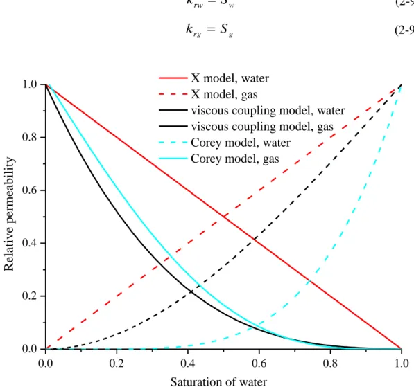
The X-model has been used to simulate reservoir behaviors for its priority in simplicity [Gilman and Kazemi, 1983; Thomas et al., 1983]. This model is derived based on the assumption that each phase flows in its own channel, so that no interference between two phases exist in their simultaneous flow. Consequently, the relative permeability of each phase equals its saturation, as indicated in Equation 2-9 and Fig. 2-2.
12
rw w
k = S (2-9a)
rg g
k = S (2-9b)
0.0 0.2 0.4 0.6 0.8 1.0
0.0 0.2 0.4 0.6 0.8
1.0 X model, water
X model, gas
viscous coupling model, water viscous coupling model, gas Corey model, water
Corey model, gas
Relative permeability
Saturation of water
Fig. 2-2 Evolution of relative permeability with respect to saturation in X-model, viscous model and Corey model (μw = 1.01×10⁻³ Pa·s; μnw= 17.9×10⁻⁶ Pa·s in the viscous coupling model)
However, the interference between phases cannot be neglected in many occasions. The viscous-coupling model accounts for the interaction between phases induced by the viscosity difference. It is derived by integrating Stokes’ equation. It is assumed that the fracture is a small sized conduit, in which the wetting phase flows at both sizes (contacting the wall) and the nonwetting phase flows in between. The relative permeability is derived as Equation 2-10, in which μw andμnw are the viscosity of wetting phase and non-wetting phase, respectively. Note that the relative permeability of nonwetting phase is dependent on the viscosity ratio between two fluids.
13
2
(3 )
2
w
rw w
k = S −S (2-10a)
3 3
(1 ) (1 )(2 )
2
g
rg w w w w
w
k S
S S S= − +
− − (2-10b)The Corey model is a commonly used approach in porous media [Corey, 1954], in which capillary pressure plays a dominant role on the relative permeability. It suggests stronger phase interference than viscous coupling model. The relative permeabilities are described as Equation 2-11, in which the Sw,r and Snw,r are the residual saturation of wetting phase and non-wetting phase, respectively.
( )
41
w wr
rw
wr gr
S S
k S S
= −
− −
(2-11a)2 2
(1 ) [1 ( ) ]
1 1
w wr w wr
rg
wr gr wr gr
S S S S
k S S S S
− −
= − −
− − − −
(2-11b)The diversity of various models indicates that their difference is induced by different mechanisms. In the next section, we introduce a series experimental and numerical studies in fractures, in which the results conform to different models.
2.3 Typical studies on two-phase flow in the rock fracture
Studies on two-phase flow in fractures can be divided into two categories, namely the displacement mechanisms [Babadagli et al, 2015] and simultaneous flow of two phases in the fractures or porous media [Fumagalli and Scotti, 2013; Hauge and Aarnes, 2009].
These two categories of studies have something in common, because the flow is under the same influence of the two-phase interactions, such as the capillary pressure. However, these two kinds of studies correspond to different types of engineering background. For example, in the gas and oil recovery, the simultaneous flow of oil and gas exists in the previous stage of exploitation, while the displacement process exists in the stage of water displacing oil. In this dissertation, we focus on the simultaneous flow of two phases.
Methods of studying two-phase flow in fractures are of two types: (1) To borrow the theories and approaches of two-phase flow in porous media. In this method, fracture is assumed as two-dimensional porous media [Pruess and Tsang, 1989]. (2) To borrow the approaches of two-phase flow in conduit. This is on the basis that the flow structures in
14
fractures are similar to that in conduit in some experiments [Fourar and Bories, 1993].
Different methods and the corresponding typical researches are introduced as the following.
2.3.1 Studies that conform to X-model, viscous coupling model, Corey model
Conventional theories on the two-phase flow in porous media, which is based on the concept of relative permeability, has been widely used to describe the two-phase flow in fractures. Romm [1966] conducted the kerosene-water two-phase flow tests in parallel artificial fractures. The fracture is composed of parallel bands with alternate wettability.
The results confirm to X model, indicating negligible two-phase interference. Analysis on the production data of a geothermal field by Pruess et al [1983] also supports the X model. Mahoney and Doggandt [1997] also showed similar results. Fourar and Bories [1998] investigated the air-water flow in parallel artificial fractures, and the relative permeability complies with viscous-coupling model. Fourar and Bories [1995] also observed results that conform to viscous coupling model. Their experiment was conducted with air and water in parallel glass plates, in which the aperture was about 1mm. Diomampo [2001] conducted N2-water flow experiment in smooth-walled fractures, and the results conform to the Corey model. This indicates that in some cases the two- phase flow behavior in fractures is a limiting case of that in porous media.
2.3.2 Studies that shows stronger interference than Corey model
Persoff and Pruess [1995] conducted air-water two-phase flow in rough-walled fractures, and they observed that the sum of relative permeabilities was much less than 1 at intermediate saturations. This indicates a more severe phase interference than Corey model. Watanabe et al. [2014] conducted a series of experiments with decane-water and nitrogen-water in real fractures with different wettability values. They also observed a stronger phase interference and proposed a new v-type relative permeability model.
Pruess and Tsang [1990] conducted a numerical study in a fracture to study the effect of capillary pressure on the relative permeability. The fracture aperture follows a log-normal distribution. Their results also indicate that the two-phase interference is stronger than that of Corey model. All of the above three studies indicate that in some cases the Corey model, which is originally proposed for porous media, is not applicable to fractures. This
15
may be because in 2D porous media (fractures) the chance of one phase bypasses the other phase is larger than in 3D porous media.
This indicates that the three models for porous media shall be revised for application in fractures due to the difference between 2D porous media (fractures)and 3D porous media.
2.3.3 Studies with novel models of relative permeability
Conventional models for relative permeability are mainly expressed as the function of saturations, which neglects the contributions of fracture roughness. In consideration of this deficiency, Chen [2005] established the correlation between the flow structures and the relative permeability in single fractures through visualization experiment. Based on this correlation, the permeability was expressed as the function of both saturation and flow tortuosity. The flow tortuosity is a parameter that is related to flow structures. Since the flow tortuosity is also a reflection of the fracture roughness, the influence of fracture roughness is included in the expression of relative permeability.
Besides the viscous coupling and capillary pressure, the inertial effect also influences the two-phase flow hydraulic characteristics. However, the influence of inertial effect is not included in the above-mentioned three models of relative permeability. Experiments by Radilla et al [2013] show that the relative permeabilities not only rely on saturation, but also the flow regimes. They expressed the relative permeability as the function of both saturation and Reynolds number.
The above two studies indicate that the X model, viscous coupling model and Corey model are not enough for describing the two-phase flow in fractures, because the three models fail to include the influence of fracture morphology and the inertial effect.
2.3.4 Studies with models of two-phase flow in conduit
Fourar and Bories [1993] observed the evolution of flow structures of bubble flow, fingering bubble flow, complex flow, film flow and drop flow in their experiment.
Because the inertial force cannot be neglected in their experiment, they abandoned the relative permeability model which cannot account for the inertial force. Since the evolution of the flow structures show similarity to that of two-phase flow in conduit, they tried to use the models developed for two-phase flow in conduit, which account for the
16
inertial effect. Their results show that both the Lockhart-Martinelli model and homogeneous model can predict the two-phase friction factor, and the homogeneous model fit the experiment data better than the Lockhart-Martinelli model over the entire range of pressure gradients. But the deficiency is that their model for the rough fracture was only applicable to the only one rough fracture which was used in their experiment.
The applicability to other fractures was not investigated.
To conclude, the effect of fracture morphology is not included in this model for predicting two-phase pressure drop.
2.4 Motivations of this research
From this review, we conclude that some shortages in the researches remain in:
(1) Different experiments show different results about the evolution of relative permeabilities. Some testing results follow the X-model [Romm, 1966, smooth fracture with alternative stripes], some follow the viscous model [Fourar and Bories, 1995, smooth fracture], some follow the Corey model [Diomampo, 2001, both smooth and rough fracture;], while some indicate more severe two-phase interactions than Corey model [Persoff and Pruess, 1995, rough fracture]. Since different researchers use specimens with different fracture surface morphologies, it is believed that different performances are induced by the difference in the surface morphology or roughness of the fractures.
Consequently, the effect of fracture roughness on the relative permeability remains to be further investigated quantitatively.
(2) The X-model, viscous model and Corey model are all expressed as the function of saturations, as indicated in Equations 2-9, 2-10 and 2-11. However, the hydraulic characteristics of two-phase flow are influenced by many factors, such as the viscous force, the capillary pressure, the inertial effect etc. Compared with single-phase flow, there are more influencing factors. It is difficult to quantify the effect of a single factor with experiments. In addition, the fracture roughness also has effect on the relative permeability. The effect of fracture roughnessshould be quantitively evaluated.
Consequently, this dissertation seeks for additional results on the effect of fracture surface morphology on the two-phase flow characteristics. The experimental study used smooth and naturally rough fractures to evaluate the surface roughness on the relative permeabilities and Lockhart-Marinelli multipliers. This helps understand what factor
17
(capillary pressure, viscous coupling, inertial effect et al.) is the dominant one in different kinds of fractures. To quantitatively evaluate the capillary pressure effect in different fractures, simulation with level set method, which accounts for the effect of capillary pressure, is conducted in the generated random rough fractures. Detailed descriptions are given in the following chapters.
18
Chapter 3 Development of an experiment system and experimental studies on the hydraulic characteristics of two-phase flow in the single rock fractures
In present engineering applications, calculations of hydraulic properties in two-phase flow are still highly dependent on empirical or semi-empirical equations obtained from experiments. However, the empirical equations that can reproduce the experiment data on a certain fracture specimen may have errors on other specimens. Sometimes researchers have obtained results that show quite different evolution forms of relative permeability [Romm, 1966; Persoff and Pruess, 1995; Diomampo, 2001; Watanabe, 2015]. This is because two-phase flow in a fracture is influenced by multiple factors, which add to the difficulty on establishing a general equation. This chapter aims at expanding the experimental results and making a further step to establish a general model. Firstly, an experiment system which can conduct visualized two-phase flow experiments is introduced. By analyzing both the flow structures and the pressure drop characteristics, the two-phase hydraulic properties in this certain rock fracture are concluded.
3.1 Development of an experiment system
3.1.1 Reviews on experiment systems for two-phase flow
In many engineering applications, the multiphase flow tends to be an important issue.
Due to the complexity of two-phase flow, a universal equation for describing all the two- phase flow problems is still absent, which indicates that the empirical or semi-empirical equations obtained from the experiments are still important in practice use. At the present stage, experimental studies remain to be a significant method to gain more insight about the two-phase flow mechanisms. What’s more, the two-phase flow in fractures is more complicated considering the influence of the fracture roughness or aperture on the fluid flow.
In addition, sealing the specimens remains to be a principle difficulty in a two-phase flow experimental apparatus. The sealing process tends to be time-consuming or difficult.
Generally, there are two kinds of sealing methods: mechanical sealing and sealant sealing.
Mechanical sealing refers to compacting the specimens and the flow box with the mechanical force. This method is time-saving and convenient. But in many situations, the
19
sealing effect is not good. Water or gas leakage may happen at some junctions. Sealing the specimens with sealant is generally with good effect, but it’s time-consuming in assembling the specimens because some time is required for solidification of the sealant.
When replacing the specimens, it takes time to remove the used sealant, meaning that this method is also costly. What’s more, in natural rock masses, fractures tend to have shear displacements. However, it’s quite hard to apply shear displacements in existing apparatuses since it causes more difficulties in sealing.
Some researchers have already developed certain experimental apparatuses for two- phase flow in fractures. Liang et al [2016] has developed “An visualized experimental system for two-phase flow in fractured rocks”. In this system, a T-type fracture intersection model was designed as the two-phase flow channel, as shown in Fig. 3-1.
This fracture intersection model can be viewed as an element of the fracture network, namely a special combination of two single fractures intersecting at 90°. The fracture surface is to be carved in a machine tool to simulate the natural rough surface of the fracture. However, in this fracture intersection, the flow of water and gas is under the gravitational effect and buoyancy in the vertical fracture, while the flow in the horizontal fracture is not influenced by this effect. Consequently, there are too many impact factors which influence the two-phase flow characteristics in this fracture intersection model, which increases the difficulty of analyzing the influence of different factors based on the measured data such as the pressure, the flow rate and the flow structures. Fan et al [2017]
developed “An experimental system for two-phase flow in fracture network”, in which experiments can be conducted in fracture networks. In addition, an effective method for
(a) The fracture specimen (b)The sealing rubber Fig. 3-1 The T-type fracture apparatus [Liang et al. 2016]
20
dealing with the mixed water and oil has been proposed. Two-phase flow itself is influenced by many factors such as the water-gas ratio, the aperture fracture, the fracture roughness etc. In the fracture network, more factors characterizing the network structure are introduced to influence the flow process. Due to the complicity of different impact factors, study on the two-phase flow in single fractures is still necessary.
Diomampo [2001] has designed a system for conducting gas-water two-phase flow experiments in single fractures. The core device of this system is a two-phase flow apparatus, which consists of a smooth glass plate as the upper plate for the convenience of observing the flow structures, and an aluminum plate as the bottom. There are two groups of ports acting as the water injection ports and the gas injection ports, respectively.
Viton is placed between the bottom and upper plates for sealing. A couple of pressure measurement ports and temperature measurement ports are set in the bottom plate. A wire mesh is inserted in between the two plates of the apparatus, which is assumed to represent the rough fracture. However, the rough surface of the wire mesh is different from that of the real fractures in rock specimens. On the other hand, shear displacement between two rock specimens will lead to a totally different aperture distribution, which will induce serious influence on the fluid flow. With this apparatus, the flow tests in the rock fracture with different shear displacements and different apertures can’t be conducted.
In this section, a newly developed experimental system is introduced. The core component of this system is a two-phase flow box, in which two rock specimens can be put in. One of the specimens is transparent for the convenience of observing the flow structures. With the specially designed sealing structure of the two-phase flow box, good sealing effects can be acquired. Since we can assemble the specimens without using sealant, the assembling process is time-saving and economical. The aperture and shear displacement between two specimens can be assigned as different values. With this system, experiments can be conducted to investigate the gas-water two-phase flow characteristics in single fractures with different roughness degrees, different shear displacements, and different apertures.
3.1.2 The experiment system
The experimental system is shown in Fig. 3-2, which includes four subsystems: the water supply subsystem, the gas supply subsystem, the two-phase flow box and the
21
measurement subsystem. The water supply subsystem includes a peristaltic pump and a pulse damper. The peristaltic pump can inject water at a specified flow rate in the range of 0-2000 mL/min, as shown in Fig. 3-3. The flow rate and pressure of the water from the peristaltic pump is always fluctuating. This is because water is injected by squeezing the flexible tube with a rotor in the peristaltic pump. To decrease this fluctuation, a pulse
Fig. 3-2 The schematic of the experimental system
Fig. 3-3 The peristaltic pump Fig. 3-4 The pulse damper
Plaster specimen
Pressure sensor Pressure sensor
Gas Gas & Water
Electronic balance
Mass flow controller Pressure regulator
Peristaltic Water Pump
Transparent specimen Camera
Gas cylinder
Gas Pulse damper
Water
22
damper is connected to the pump. As shown in Fig. 3-4, the pulse damper has an inlet (at the bottom) and an outlet (in the above). Inside the pulse damper, the upper space is filled with air while water flows through the lower space. Due to its great compressibility, the air will swell and contract periodically, whereby the fluctuation of water pressure and flow rate will be decreased. Consequently, water flows out of the outlet with stable flow rate and pressure. With the peristaltic pump and the pulse damper, water can be stably injected to the two-phase flow box at a specified flow rate.
The gas supply subsystem includes a gas cylinder, a pressure regulator and a mass flow controller. Nitrogen is supplied from the gas cylinder, in which the initial pressure is within 0~14 MPa. With the pressure regulator, the gas pressure can be decreased to be the value within 0~0.2 MPa to protect the mass flow controller, since the mass flow controller cannot bear a pressure over 1 MPa. The mass flow controller can inject gas into the two- phase flow box at a specified rate between 0~5000 mL/min. The two-phase flow box is the core component of the experimental system. Two rock specimens can be put into the flow box, and one of the specimens is transparent for the convenience of obtaining the flow structures. The measurement system includes the pressure sensors, the camera and the electronic balance. They are used for obtaining the flow pressure of both phases, the flow structures and flow rate of water, respectively. This experimental system has the following advantages: (1) To conduct the visualized two-phase flow experiments in single fractures, meaning that the flow structures can be captured; (2) Rock specimens with different roughness degrees can be used in the system to study the influence of roughness on the two-phase flow characteristics; (3) The specimens can be placed with different apertures to investigate its influence on the two-phase flow; (4) The specimens can be placed with different shear displacements to investigate its influence on the two-phase flow; (5) A specially designed mechanical sealing method is used to seal the specimens.
Sealant is not needed in the process of assembling or replacing the specimens, and consequently it’s time-saving and economical. With this experimental system, the two- phase flow characteristics can be quantitatively studied to understand the two-phase flow mechanisms in engineering applications such as coalbed methane recovery, CO2
sequestration and nuclear waste storage.
Since the two-phase flow box is the core component in the experiment system, it is introduced in the next section in detail.
23
3.1.3 Two-phase flow box
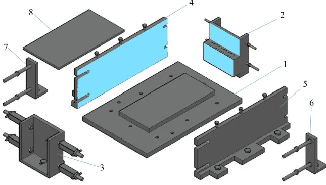
The two-phase flow box is manufactured with stainless steel. It is composed of one pedestal, two long-edge side plates, one fixed short-edge plate, one mobile short-edge plate, two L-modules, five pieces of rubber sheets, spacing shims, displacement shims and other accessories. After assembling the above-mentioned components, mechanical force can be applied on the specimens by tightening the screws, whereby the specimens can be sealed. As shown in Figs. 3-5 and 3-6 (a), the components include:
Fig. 3-5 The components of the two-phase flow box
1--Pedestal. The pedestal has a raised baseplate, on which the specimens will be put on.
The length of the baseplate is 220 mm, which is 20 mm longer than the length of the specimen (200 mm). Several tapping holes are set on the pedestal, which are used for fixing the pedestal with other components.
2--Fixed short-edge plate. The fixed short-edge side plate can be fastened on the pedestal.
A rubber sheet is pasted on the inside of this plate. There are 10 water injection poles and 10 gas injection poles on the plate. The height of the gas injection pores and water injection poles is 50 mm, which is identical to the thickness of one specimen; in this way the gas and water can be directly injected into the fracture between the two specimens.
1 4
5 2
3
6 7
8
24
3--Mobile short-edge plate. The mobile short-edge side plate is also fastened on the pedestal, but the position can be adjusted. By adjusting its position, the specimens can be compacted. A rubber sheet is pasted on the inside of this plate. There is an outlet on the mobile short-edge side plate for discharging the water and gas, as shown in Fig.3-7.
4,5—Long-edge plates. Two long-edge plates are also fastened on the pedestal. Rubber sheets are pasted on the inside of the plates.
6,7—L-modules. Two L-modules are fastened on the pedestal. They are connected to the mobile short-edge plate by the bolts. By screwing up the bolts, the position of the mobile short-edge plate can be adjusted to compact the specimens.
8—Transparent acrylic plate (not shown in Figs. 3-5 and 3-6). This acrylic plate is fastened on the long-edge plates with bolts. It is used for controlling the vertical displacement of the upper specimen under the water and gas pressure. It is made transparent for the convenience of observing the flowing structures.
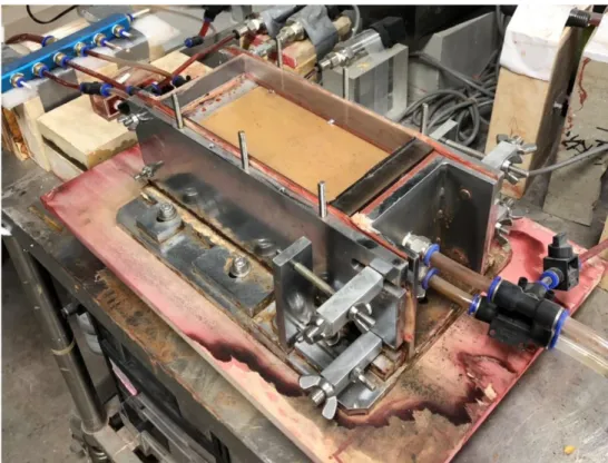
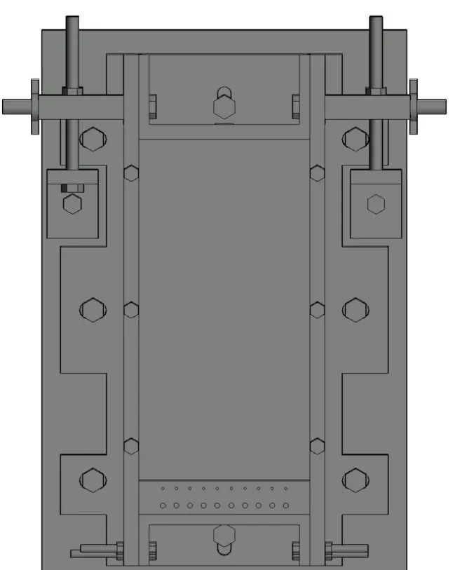
In Fig. 3-5, the blue parts refer to the rubber sheets, which are used for sealing up the specimen. Fig. 3-6 (b) shows the physical picture of the two-phase flow box. Figs. 3-7 shows the side view (in the direction of width), in which the outlet of fluids is clearly shown. Figs. 3-8 and 3-9 show the vertical view and the side view (in the direction of length) of the two-phase flow box.
(a) Schematic (oblique view)
25
(b) The physical picture
Fig. 3-6 The assembled two-phase flow box
Fig. 3-7 Two-phase flow box--side view (in the direction of width)
26
Fig. 3-8 Two-phase flow box in vertical view (without specimens)