Architectural Institute of Japan
ArchitecturalInstitute of Japan(at
Rl
UDC:691.32:539.374PLASTIC
LAn'
Journal
ofSttuctural
andConstructioo
Engineering
NdynM\kesxxXtsNvatsff
'
ng
377e・mata
62
e7fi
CTransactions
efAIJ)
No.
377,July,
1987'
DEFORMATIONAL
BEHAVIOR
OF
AXIALLY
'
LOADED
CONCRETE
UNDER
LOW
LATERAL
PRESSURE#
'
'
Evaluation
Method
for
Compressive
Toughness
of
Laterally
t
tt
tt
tt/t
Confined
Concretes
(Part
l)-
・
/t
/t
'
tt
by
SHIGEMITSU
HATANAKA*,
YOSHIO
KOSAKA**,,.
and
YASUO
TANIGAWA"'
Members
of
A.
I.
J.
gl.
tntroduction.
'
.,
For
the
applicationof
the
plastic
design
methodto
reinforcedconcrete
(RC)
frames,
it
is
the
first
requisitethat
constitutiveRC
;nembers areductile
enoughfor
the
redistribution
ef
mornent andfor
the
formation
ofplastic
collapse
mechanisma).It
is
well
knowp
that
the
preferr,ed
failure
pattern
ofRC
members
is
a
flexural
failure
preceding
type
with adequate warning
of
collapse,
then
increase
in
the
toughness
(energy
absorptien
capacity) of concretein
the
compressive zone ofRC
membersis
qttite
effectiveto
improve
their
ductility,
.
It
has
been
pointed
out
that
the
mechanism ofthe
toughness
improvement
of
confined
concrete and steelfiber
reinforced
.concrete
under
cempressionis
malnlydue
to
the
lateral
cenfining
effectgf
lateral
bars
and steelfibers
causedby
the
Poisson's
effect of cencrete afterfailure5).
This
effect
can
be
easily relatedto
th.e
behavior
ofplain
concrete under multiaxialstfess
states61'l?).Thus,
it
is
possible
to
discuss
systeinatically
the
toughness
improvement
of various
kinds
of
laterally
confined copcretes,based
ontriaxial
cempression
test
data,
especially enthe
post-failure
behaviQr
of concrete under.,alow
confininglateral
pressure
ofless
than
about20kgflcm2iO),
However,
information
is
not
adequate
to
date
to,develop
areliable constitutivemodel
including
such apost-failure
behavior
ofcoticrete'L]i)-i3).
Some
ofthe
main reasons arein
the
difficulties
in
the
c6ntr616f
sitrain
rate andthe
measurement oflateral
strains, resultedftom
the
fact
that
the
dilatation
of concretebeYond
"ltimate
stressis
remarkablein
this
range
of
lateral
pressure.
The
authors,therefore,
have
developed
4
triaxial
testing
methodin
which ahigh
rigiditycompression
testing
machine and a,newtype
of
lateral
loading
device
are combined, and cenfirmed, usingthis
method,that
fundamental
information
can
be
obtainedfor
discussing
the
mechanism ofthe
toughness
improvement
of
laterally
confined eoncretesi4)'i6).There
are
two
maip
purposes
ip
the
present
study,The
first
is
to
propose
an
evaluatien
systemfor
the
effect of varioustypes
oflateral
confinements onthe
compressivetoughness
ofc6ncrete,
based
onthe
behavior
of concreteund,er
triaxial
compression(Part
1,).
The
secondis
to
discuss
in
terms
ofthe
toughness
evaluation
systemthe
rationalcombination
pattern
of concrete and othe: materials, especiallysteel,
to
provide
a requiredductilitY
to
RC
members
(Part
2).
,
The
present
paper
<Part
1)
describes
the
re$ult efthe
investigation
relptedto
the
first
purpose.
First,
the
effectof
various
factors
onthe
plastic
deformational
behavior
of
boncrete
undertriaxial
compression was examinedin
an
experime,nt.Next,
'a
systematic methodbased
onthe
triaxial
compressive
test
data
wasproposed
for
the
evaluationof
the
compressive
tbughness
of variouskinds
oflaterally
contined concretes.Further,
the
stress(
a,)-strain<
Ei)
curves
in
the
direction
ofthe
maximumprincipal
compressive stre.ss were numerically expressed,the
expressionbeing
usedasastandard
in
the
eyaluation
system.
,
'
'
.
'
#
This
paper
is
based
onthe
earlier workspresented
in
Refs.1)
through
3).
i
ReseaTch
Assoeiate,
Department
ofCivil
Eng,,
Nagoya
Univ.,
Dr.
ofEng.
i-
Professor,
Department
ofArchitectute,
Nagoya
Univ.,
Dr.
ofEng.
・
i"Professor,
Department
ofArchitecture,
Mie
Univ.,
Dr.
ofEng.
(Man"script
reeeiyed・,June2,
1986)
-27-Architectural Institute of Japan
NII-Electronic Library Service
ArchitecturalInstitute of Japan Notationof SpeCinenw!cHIDtt
'eLCkgf!cm2}s'Ccm)u'
o・loo ,l・3 o.4+"'e.g.)'-S-1-O.4I,Igii/E::o-4
Ta.U.:#ik.Ylf.!te.Ms2t 5+10+L1.01.32.e'
e O.45.O.55,O.,70e 6+1j 5'o10o 12t25・10g2;
Experimental
procedures
'
'
.,'
''.
'
'
tt
ttt
2.1
Outline
of experimentThe
outline
of experimeptis
shownin
Table
1.
The
variablesin
the,experiment
werethe
water-cement ratio(vrIC=O.45,
O.55,
andO.70).1
hei'g'
ht
{H)lwidth
(D)
ratio of specimen'(HfD=1,1.'3,
and
2),
magnitude oflateral
pressure
(
a.=O,1,
3,
6,
and12
kgflcm2.
Here,
these
values of aLg'raduaHy
increaSe
from
about E,=5 ×IO-3
in
the
stressdescending
rangedue
to
the
rapid
dilatation
of concrete・in
the
experiment),
spacing
ofloading
point
of'
lateral
pressure
(S=o,
5,
and10cm'),
arid
friction
atthe
sb'ecimenlloadingplaten
interfaces
(coefficient
of staticfriction
"=O
andO.
4).
The
term
"pressure(
aL)"is
usedfor
tfe
representqtionof
the
balanced
lateral
stresses,i.
e. ai. =a,=ala, andthe
subscripts
ofboth
stress(a)
and strain(E)
.represent
th.e
co-ordinate axes(see
Figs.
1
and2),
compressionbeing
positive.
The
cross-section
of s'pecimerifor
the'triaxial
test
waskept
to
loxlocm.
Three
specimens
were
prepared
for
gach
variable.2.2
Fabrication
hnd
curihg of specimens'
'
・'1-'
Ordinary
Pbrtlarid
cement, riversand
(maximdm
size:
'5
inm)
and rivergravel
(size
range:s-lsmm)
wereprepared
for
concrete.The
slumpof
concretes
wasdesigned
t6
be
5
cmfor
allthe
batches
in
orderto
minimizethe
'
variation
of
mechanipalproperties
ofthe
specimens resultingfrom
bleeding.
Concretes
were
cast
into
stbel molds and consolidated witha
woodenhamrner
and arotarytype
poker
vibratorfrom
the
outside ofthe
molds.
All
the
specimens'
were capped with cement
'paste
at
thle
age
df
1day
and
deinolded
ht
the
age
of
2days,
andthbn
curedin
an airconditioned
room
<23
±20C,
relatiye'humiditY
7s
±s
%)
untiltes'ting,
exc'eptthat
somecylindrical
spe6imbns were cured'in
"rater.
The
tests
were carried out atthti
ag'e'
ol about50days.
・
'
'
'
'''''
'
z.3
Methods
of
loading
and'measurement
'
・
''
L
'
''
'・・
・
・A
triaxial
dompressive
loading
clevice
itlttstrhted
in
Fig.1
'
.
t
tTable
1
'Outline
of experiment'i
''
''''was used, with which arbitrarylateral stresses'are applied'
to
tt
the
sipecim'en
by
mea'n'Sof
'the
flexutal'moment
rlesistance of'steel
plates.
The
lateral
loads
applied
are estimatedby
the
straih'of steel
6olts
setbetween
the
steel
platen
and a steelbarl
The'initial
values oflateral
'stresses
are controlledby
''
tightenirig
the
steelbars
with nutS.All
the
specimens wereset uPside
down,
'that
is,
a cappedsurface
WaS
setdn
the
'
othdr' s'ideiof atiltlng
platen
(see
Figs.1
and2)
in
orderto
ENotes]
wlc: water-cement ratso, HID, H.i.ghtl alleviatethe
'concentration
ofthefailure
in
a'specimenm.
All
gidst,h.:f.8P:;
±:::s.a.l:.t:grr,a.r.70:{iX;g7.:;・i::2
'the
specirnefis
for
the
uniaxihlahd
triaxial
testg
W6re
l6aded
Zgl":1'O,S,70flfiglr,"t,:;
fi;:://C.;r:i:,tl87g,r"i??iY'
ih
the
16ftgitudinal
('first)
direction
underthe
constant slrain:;e.yof:E.HfD=1
and 2 of WIC'O・5S, '": O"IY iOrrate of about
2
×loL31min."by
using
ahigh
rigidity'cbmL'' i
'''
"'prb'sgion
testing
thachine.'
For
the
di$persed
t'y'pe
lateral
lp.
p.,.d.i.g・.・,t'b.'rOugfi・・
・
,T.i,!!iR.g
piaten'
'
'
cohfineinefit,
asetdf
steelbars
with
S'><5mm
sebtion' wereMechinePIaten
Stee1E..ifl..t.e.n.
Yieldlng,Section'Stee1Boltt.t.
./
w・s,,.g.r.ls.・set'between
'a
specimen'hnd
・'Fig.7(a)).
'
The
complete stress-strainX-Y
recorder upto
a specifie
,
,/ .
.t
,1.
.・
・
Yielding
5qction
lateral
loadirig'platens
(see
.
t.
1.
/
t. 1 /,
.
curves wefe recorded
by
and
s'train<E,=30
×10-3).
The
'
Ol,El
/
.t
{a)
Exterior
view
FIg.1
Triaxial
loading
;,
"
(b)
Section
/t
device
'
S.G.,s
I,・.・
'
/
U2,e2.U3tE3
Capped
.-
Cast
tt
'
Flg.2
Convention
fer
subscripts'
'
'of-stress
and・'str'ain---
28
-Architectural Institute of Japan
ArchitecturalInstitute of Japan
'
friction
atthe
specimen-loadingplaten
interfaces
was reducedby
placing
friction
reducingpads.
The
pad
consists oftwo
polypropylene
sheets with silicongrease
between
them,
with which sufficient uniformity of stressdistribution
onthe
ends ofthe
specimen canbe
expectediS).
It
was confirmedby
using "pressure sheetsr']S}placed
atthe
'
specimen-platen
interfaces
that
the
laterai
stress
distribution
induced
by
the
loading
device
was adequately uniform.For
allthe
spticimens, a couple ofdifferential
transformers,
were setbetween
the
tilting
platen
andthe
machinebase
platen
to
measurethe
over-all' strains.For
cubic
,specimens,
lateral
strains were measuredby
two
deformation
'
transducers
as shownin
Fig..1.
For
the
specimens ttnder uniaxialcompressio-,
two
c6upies of wire straingages
(W.S.G.
)
we;eglued
to
the
specimento
measurethe
longitudinal
andlateral
strains.'
'
93.
Test
resultsand.discussion
・
'
'
'
Since
the
displacement
w'as measuredby
a
couple
of
differential
transformers
setbetween
platens,
the
strainin
the
stress ascenaing
portien
ofthg
curvesis
over-es'timateddue
to
the・p'resence
ofthe
friction
reducingpads.
Therefore,
the
uniaxiallongitudinal
tst'i
ess'1(a,)-longitudinal strain(E,)
curve was used upto
the
stress at whichthe
tangent
'
modulus of a,-si curVe
from
the
!riaxial
test
becbmes
compatible
withthat,of
the
curvefrgm
the
uniaxialtest,
3.1
Failure
patterns
of specimensTypical
ultimatefailure
patterns
of
various shapes of specimens are shownin
Photo.
1.
As
seenin
Photo.
1,
cracks
extend
thrQughout
the
wholeheight
for
the
specimenof
HID=1
and1.
3,
while crushing occurs only atthe
upper end zone which correspondsto
the
upper-zone of specimen at casting,for
the
specimen ofHfD=2.
This
trend
is
observed regardless ofthe
level
of
lateFal
pressure
applied
in
the
experiment.'
'
3.2
Effect
of magnitude oflateral
pressure
Figures
3
(a)
and(b)
showthe
effects of uniformlydistributed
lateral
pressure
onthe
deformational
behayiors
ofthe
specimens ofHID=1
and2,
respectively,For
bdth
shapes of specimens,large
increases
in
load-carrying
capacity andtoughness
are observed even under asitialllateral
Pressure
such
as
at=3kgflcm2,
The
increases
in
peak
stress and
toughness
due
tg
a certainlevel
ofIateral
pressure
are almost constant regar.dless ofthe
HID
ratio of'
specimen.
Furth,er,
lateral
strain at acertainlongit",din'al
strainlevel
in
the
stressdescending
rangedecreases
almostproportionally
to
the
magnitude oflateral
stress.3,3
Effect
of wateT-cement ratig・''
'
Figures
4
(a)
and(b)
showthe
effect of water-ceinent ratio(
WIC)
onthe
a,-e,
curves.A
similartrend
ofthe
effect ofWIC
onthe
at-Ei curve of concrete under uniaxialcompression,
is,obs,erved
for
concrete undertriaxial
tt
compression,
Namely,・the
strainleve.1
at-the
b'eginning
of convergingbfanch,
whichis
usually observedin
the
'
descending
portion
ofthe
q-Ei
curves ofthe
concrete
under
uniaxial
compression]9),gradually
increases
withincreasing
lateral-pressuTe.
The
concrete specimen atthis
strain
level
is
consideredto
sufferacertain criticaldamage
regardless of
the
strength of concrete.,
3.4
Effect
ofheightlwidth
ratio of specimenFigure
5
showstheeffect
of
HID
ratio of specimen on cr,-E, curves.The
stress andstrain.
at
the
peak
point
slightlyincrease
withdecrease
in
the
HID
ratio of spegimen.The
effect ofthe
HID
ratio of specimen onthe
shape ofthe
'
-
-
'
descending
portion
of a,-}, cur"eis
quite
remark-mrmua1l・M.ik'IX,xffrmt
s,
sti's':,g'g,:.L'i
ulD"l-3.,wuth-.a.7 kgFrkflfi
,...,.ne.:.,fi-l.,(toweF,
'e.h''dL'''eoi,r.Ss'"p,gnd"
Ill:
Pheto.1
Typicar
ultimatefailure
patterns
t
t
able regardless of
the
magnitudd oflatelral
pressure,
i.e.
the
shape ofthe
curvebecomes
steep asthe
HID
rat.i:oof specimenincreases,
Such
change
is
almost
independent
ofthe
magnitude-of
lateral
pressure.
'
It
is
Well
known
that
i)
the
a,-si curve measuredin
a conventional'uniaxial
compression
test
is
significantly
influenced
by
the
strain measvrement region andii)
it
is
quite
important
to
make clearthe
equivalence ofthe
failure
zones of atested
concrete
specimen
and a reinforced concretemem-ber
to
whichthe
a,-e, curveis
to
be
appliedin
the
-29-Architectural Institute of Japan
NII-Electronic Library Service
ArchitecturalInstitute ofJapan ' -Rcn,s).t"wzaN8 eom
6o"
oon. oopt eo・--Rpt-B".bvzaH: e eeut oe" eom oDpt // 'ttt
-20
ooH-16-12
.t/
HID=2 w/c=e.ss,t-UoL.-'-r.Zre.9i"kgg[f/icptpt'7
.o
-e-4STRAIN(a)
TENSION,e2=e3f/cpt12
..tl "l-."3lpxggtfcrb t #sxle-3, 1-3
[ tlOxlO 1,..1
.
f''
olrel Os,EsEs/.tt.///
o(xleHID=)
-3
VzJEI 4) e coMPRESSION.,elt:t
e St"olgfe(?ILY
・12.
,
'1
t' 16///
OLt"3
QL'S6-9',
tigtyeTn2
t7
kgt?Ih2'
"
'kflizae''
''' ' uo Ae eszaE"neB
tn m,-NX.q.
x,B
'NH'tv
,
,
q.'
v i20o/T
' uegg
zaE
n'gza'
za
;.N."
g.
wP'-eq v i・,' ,i2 o ,
/t
・-,
o.,,,..Nfi"tpE
8
za
:
oe" eon ee" eoH o-20
Fig.3
r'-IS
Effect
of's ,l,
N
-12
lateral
'-s!
.L
/)
pressure
(q)
z4
''
b''
4 STRAINCXIe:1)
・(b)
,HID-2.,
On al-EL, Eh and EsD24
S
S
10''12
14,
16
le 20sTRAIN
{xlo--3}
,[1'
'
'
'
(a)
HID=1
'
Fig.4
Effect
of water-cement-Re--E)xo
zaNza
ratio eow eem oeN oeH oe
curves ef aitially /tt16
loaded
20'cencrete
e(vafc}
246e le 12 STRAINC
x 10-3)(b)
HID=2
On aL-et curves 14 16 IB 2e tEI30
Architectural Institute of Japan
ArchitecturalInstitute ofJapan
deformation
'analysisi7i・eni'22].
Koyanagi
et a12Z). reportedan
analytical
model
for
the
load-deformation
curves of specim6ns,rangingfrom
HID=2
to
4
in
whichthe
deformations
in
failure
and
elastic
zones
are
superimposed,
In
the
experiment,
the
castingdirection
of concrete was normalto
aloading
a\is.and
the,friction
atthe
spgcimen-loadingplaten
interface
was
not reduced.The
authorsi6)discussed
the
relation /betweenthe
length
offailure
zone andthe
measured
a,-e,curve,
based
onthe
data
from
atriaxiai
test
ofthe
specimens ofHID
=1to
2
in
whichthe
casting
direction
of concrete wasparallel
to
the
loading
axis andthe
friction
was reducedin
the
same manner asin
the
present
experiment; and
proposed,an
idealized
failure
zone model shownin
Fig.6
(a),
Based
onthe
Photg.
,1
andprevious
evidences]6),
the
ai-e, relationin
the
idealized
crusheq zone.is
E
o[g.-mgi-g-.8,NgUH'o
Fig.5
D 2 4 6 e 10-12 14sTR"LIN
cxlo"3),tl
Effect
ofheig'ht/width・
(HID)
speclme,n onla,-sl curves
16 le
'2D
ratio ofassumed
to
be
equivaientto
the
a,-E, curvefrom
the
specimen ofHID=1
as well asin
the
earlier reporti`).The
dashed
lines
in
Fig,
6
(b)
arethe
predicted
a,-E, curvesfor
the
specimen ofHID=
1.3
and,2, obt4ined onthe
cpndition ofl.=D(l.:length
ofidealized
c.rushed zone,D
:
width of speclmen),The
predicted
curves arein
good
agreement with experimentalgnes.
Aithough
the
ai-ei curves
for
the
crushed and non-crushed zonesbifurcate
at
the
peak
point
in・
the
presept
model,the
internal
failure
of aspecimenprogressively
develops
.after
the
critical stresspoint,
Therefore,
different
ai-Eicurves
should
be
provided
after
the
critical
stress
point
e.g.,afterO.8Fc
(Fc:peak,
stress) regardlessof
lateral
stress
level
fpr
mo,redetailed
discussion.
,・
.
'8za:
For IdealtzedL-!-, o shetl STRAIN(a)
Idealized
Qo"Nbe
.o.-.
ptNs>eMOe.Jgeg$-・
efailurezone
rnodel O24 tFig.6
eow e".g.AMgx"oe.: rv8za:za
-o02(b)
Cernparison
4
6 8 10 12 14sTRAIN
(
x 10-3)
,El・between
measured and16
le
20predicted
curvesfi
e 16 o 246,s
lo
o 246sTRILIN
(x10-3]
,El(c)
Prediction
ofpost-peak
a,-E, curvesIdealized
failure
zone model andits
applicabilitye lo
-31-Architectural Institute of Japan
NII-Electronic Library Service
ArchitecturalInstitute of Japan
'The
appli'cabilitY o{the
present
modelto
the
pre'dictiori
ofthe
stressdeseending・portion
is
discussetl.
Figure
6
(c)・
shows
the
bomParison
bet"ieen
'the
ptedicted
ahd
the
measured a,-'e, curvesin
the
stres's'descending rangefor
the
specimens of
HID
='2 with' various compressiive strengthshnd
lateral
pressitires.
Fairly
good
agreementis
observedbetween
the
tWo
'cinrves
regardless oftlie
level
of・lateral
pressure
for'
ViilC!'O.
45
andO.
55,
whilethe
predicted
cuf"es are
gteeper
thhn
the
mehsured ones,''andthe
dif'ference
becomes
larger
asthe
level
oflateral
pressure
dee'reases
for
WIC=OL'70L
One
ofthe
reason's'for such adifference
in
prediction
thay・be
due
to
the
fact
that
the
failute
ofthe'
6oncrete
ofWICtO,
70
is
ratherductile
comparedto
-that
ofWIC=O.
45
andO,
55,
Namely;''due
to
the
relatively/
.
smdll'degradation' of
the
loadlcarrying
eaPacity
i'n
the
'crushed
zone!,.tbg
failure
concentration orthe
st{,ainlocalization
iS
consiideredto
be
alleviated,In
order't6
refiledt sdch atrend
in
the
present
model,the
length
ofthe
ciushed zone(l.)
shouldbe
slightlyincreased.''
'
.-'
'
'
,.
t
t
ttt
3.5
Effect
of'dis'persedlateral
confirfeinent'・-・
'-...
''
,..".・'
,,
tt
/
.t
t
In
the
preliminary
experiment,it
was'observedthat
the
a,LE, curveis
pgtin'fluenced
so muchby.the
arrahgement oftt
t
/
t
la'ter'al
'bars
<E]
andD)
for
the
pitch
(S)
df
10
cm.''Therbforelin
the
presit/'
nt study,'the
f61meg
arrangement wasadoPted,
'Figufe''7
(a)
Sh'ows'
the'effects
of
the
pitch
-(
S>
oflaterti1
confin'emhe'nt o'nthe
al-e,gurVes
gf
concrete,T.
h'e
t
/
ttt"
t.
evident effect of
the
Pitbh
is
not observed onthe'stress
and
strain atthe
peak'point
asfar.as
the
present
experimefitiS
'
'
concerned,
i.
e,the
pitch
(S)
being
lesS
than
the
width('D)
of specimen and.thelateral
Pressure
being
not morethan
t
tt
tt
12
kgflcm2.
HeweVler,
the
effect efthe'
disPersion
Of
-late'Ta'1
pre'ssure
becgmes,
gradually
remarkable afterthe
peak
point,
that
is,''the'
decreasb
in
the
10tidicarryin'g
capacity ofti
specimenbecomes・larger
asthe
pitch
increases.
Furth'er,
suchtrehd
6e'comes
m'eteinarked'with
iric'tease
in
the
lateral
pressure.
Figttre,7(b>
shows equivalentlateral
pressures
(i,)
for
the
sPecim6ns6f
HID=1
and2
under'dispersed
lateral
confinem6nt', whe're'theq-e,
curves ofthe
specimens are evaluatedby
those
ofthe
specimens under uniformlydistributed
confinement.g4.
Evaluation
apd
estimation
of
compressive
toughness
of
iaterally
confined
concretes
4.1
Equivalent
later.ai
pressure
t/
The
improvement
of compressivetoughness
of concretedue
to
lateral
confinernents canbe
evalttatedin
terms
of"equivalent
lateral
pressure
(iL)"
.which
is
defined
as apressure
whose effect onthe
load-carrying
capacity of aspecimen at a certain strain
leyel
is
equivalent,t,o
that
by
uniform.lydistributed
lhterti1
pre'ss'ure,
The
equivalent'
lateral
pressure
is'
given
as afunction
of s,f.fai,n(E,)
by
c;omparing
the
a,-i,curves
ofthe
confined
concretes
under
uniaxial compression and
those
ofplaip
cpn' crete unaer a..certain
triakial
stress state:One
ofthe
standard conditions'
adopted
in
the
piesent
studyis
as"follpws:'
t
t.
'
'
Shape
of specimen:HIDLI・
'
・,
ttt
t
Loading
path
of1titeral
pressute:active
loading
''
.
'
Ratio
oftwo
lateral
stre.sses:atla3=1
,'
'
V"
Leading
point
oflateral
pressure
:
uniformlydistributed
overlateral
surfaces'of specimen
t
tt
t
tt
t
leA.
S=OC:Ao
:
rw Y o o o M'
g
L'
N w!c=e.ss1
g
H
:
b-:ptEq"t'n58za: Q0246
e
10
12 1416
sTImlN
Cxlo-3),[1
(a)
al-El curves'
Fig.7'
Effect
ofpitch
IS 20
E>'MO,
zaE
s::::,zn8
(S)
bf'lateral
e O 24E B 10 12 14sTRAIN
{xle-3)
.Ei
(b}
Equiyalent
lateral
pressure
confinerne'nt on' a,-ss curves
IE IS 20 culves
-32-Architectural Institute of Japan
ArchitecturalInstitute of Japan
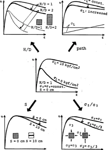
Here,
activeloading
meansthe
loading
path
in
whichthe
latgral
stresses(
cr,,-op)
are appliedto
aspecimen
before
axial
loading
(
ai),The
effects
of
variousfactorS
onthe
a,-s, curve,,of concrete underthe
abovestandard
condition are schematically shownin
Fig,8.
The
evaluation
of oi-ei curvein
terms
of.the
equivalentlateral
pre.ssure
has
a
significant merit,Since
the
equivalent
lateral
pressure
(Vt)
is
aphysical
quantity,
it
is
consideredpossible
to
estirnate
to
seme extentthe
toughness
improvement
due
to
the
combination of varioustYpes
of comPosites(multi-order
composites)just
by
superimposingthe
each value ofli,
and,if
necessary,by
introduc.ing
areductioncoefficient
for
the
combination of6,.
The
equivalent
lateral
pressure
for
the
multi-order compositesis
calculated e.g.
by
usingEq.
(
2
)
in
Table
2,
wherethe
effects ofthe
factors
treated
in
the
present
study are assvmedto
be
independent.
4,2
Stress-strain
modeltt
The
stress( ai>-strain(E,)curves
in
the
direction
ofthe
maximumprincipal'
compressive stress were numerically expressed.Tension
is
pbsitive
here
in
the
calculation
offailure
criteria.For
n6r' mhlizing stresses and strains,the
absolute values
of
the
uniaxia1 compressive strength(alr)
andthe.strain
(s.)
at
the
uniaxial
compressive
strength were used as standards,(1)
Strength
failure
criterionThe
four
parameter
fu,nction
usedin
Ottosen's
criterionZ3)・24)
{see
Eq.
(
1
)
in
Table
3),
which
is
rather simple and maybe
easily calibrated, was usedto
express a strengthfailure
envelope,As
seenin
Fig.9,
however,
Ottosen's
criterion(dashed
line)
provides
slightlylower
valuesthan
the
data
obtainedby
the
authorsi-)'i6] and
Mills
et a125).in
the
range of relativelylow
lateral
pressure.
Therefore,
the
parameters
in
the
function
were calibratedbased
onthe
present
ex-perimental
data.
The
obtained valuesof
the
parameters
and
the
criterion are shownin
Table4
andFig.
g
(solid
line),
respectiyely,It
was also cgnfirmedthat
the
modified criterion
is
in
rathergood
agreerpent
withthe
experimental
data
in
the
range ofhigh
lateral
pressure
reportedby
Richart
et al,,Balmer,
etc24),(
2
)
Strain
failure
criterionStrain
atfailure
(ev)
was assumedto
be
given
by
afunction
ofthe
first
invariant
of stresstensor
atfailure
{Ar)
in
the
form
efEq.(2)
in
Table
3.
The
reason whythe
criterion
was expressed onlyby
the
value ofLt
orhydro-pressure
componentis
asfollows:
i)
consider-able
scattering
is
observedin
the
measured valuesof
the
strain at
failure,
iO
it
is
quite
difficult
to
precisely
measure
the
strain
at
failure
in
atTiaxial
test,
andiji
)
in
actual
confined
concretes,increase
in
the
deviatric
stress component
due
to
the
irnbalance
oftwo
lateral
stresses
is
rathersmall.
Figure
10
showsthe
comparisonbetween
the
proposed
strain
failure
criterion andthe
experimental
data,
empirical con$tanta
in
Eq.{2)
in
Table3
being
determined
to
be
2.2.
(
3
)
NoTmalized
stress-strain
relationshipsThe
expressionof
normalized
stress(a,la,)-strain
(EilEc)
relationshipfor
concretesin
uniaxialcompress-
o-,L.-±
L--ks' VSI..--x....<XAV".
"NLHID=l
HID=2
#
ee
-H!D=1
HID=2L--g-HIDIsxe
t e a1.-s/
oe/
N
cr2io3
e2tej o3 Cl"e ele
;l
.
ee
..e2.
ee.
't
02;e3 a'2;a313 ed es=o
SkOs
E
"2eeq cTnse
sIO
cm e eFig.8
Efiects
of variousfactoTs
on triaxial concrete under standaTd conditionTable
2
Estimation
of equivalentlateral
composlte concretes
Ol-Elccurve of
pressure
for
For Eirst-OrderComposites
For
oLtEl) ia.B(El)
・yC[
D
-eL
---
a)
where, a; Ceefftctent coneerntng rotto uf two leteral stresses.S(El); Coefftctent conceTning p±tch of copfined p/]ints,
TCEI}':Coeffl[tent concerntng lnter,/1stres.g pnth, eL: Mnximum loteTnl pressure
tir
m:txln/"/:/ nveritge t)f Lvt!lateTal stressps expected. Multi-Order Composites' Ol(El)=ZULiCEi)
i=?(ori・BICeD-Ti{[i)・crti)-""'T""""--t2)
--Architectural Institute of Japan
NII-Electronic Library Service
ArchitecturalInstitute ofJapan
/'
Table
3
Stress
(a,)-strhin(ei)/'modet
'
strength Failure crtte'rlon
(u
''
'
'
'
'
fc!,,J.,cos3e}
=
Au:; + xgtt +B}t/-
x=
o---:---;'--")
'
"here-
ti:Fltet t"vartlint' eE strLss tenset, JhJs:kecend and thtrd tnvartants/,
:[.::E::7,S.e;・
;・
:;::
.t::::;I:::r:xtl:tk.gsv"::::g:,f:m,',f;:::;,es,
,,.
.
/, A,,B,K}tKfiEirp±ricaleaTaneters,
,,
.
,,
,.
i St:ain pailure Criterion E
,.'
''
,
'
/ ttflic=TIIIflucla
,-.""".----"-"-"---"-"-"-"-"L.(2)
t
,
vhere, Ec:straltt at'un
±axtal cmp:essive,strength
!IE:ll at fatture
Relative Stress(oifetfl
-
Relative StrainCEilei
(posttive
value),)
Relatien 1'/
/''
ttt'/'
t
'
e7cendtng
portion: aa,it =, na-:+`7!,Eiff) a---""--[ip}.
descenaing
portien:ISiaif
=nid + ndn.
-il+
i:
---L---c3is)
ndaandl
---[3c}
'
,
ulf,e:f:Sttese a"d stretn at Eatlure tn the d±Tect ±en ef maxtmumprlnctpal compresstve etreets, X=
(EliElf)M,
na= Eit{Et-(alfiE]f)}, nd=rrattdf; ndlmd fer tintaxtal eempresstve strese etete, El:lnitialmodulue oE elasrtctty, m,a:Emptr ±eal censtsnts:
,
'.J
, ,'
,
SFre?t/ Strees vheTe /ttt uR[n"1ny o"ER-tsS8za: m-ptH--eHeedio'e-t.tt
Proposed'Model i/ Ottosen's /t o tto ixx'
'''-O.5 -O
,Fig.9
D Oata by Mill.s et al.
.6
-O.7
-O.B
-O,9
-1,O
-Li
Ii!(ffgc],
Strength
failure
criterion./
.
oT
9
r
R
,/"
Y
v
ny
o"$o,
U" rvI,eq
v
vr
,?
1
er7
9
¢
'RJx
a=2.5a=2.2a=2.0/t
e1flEc;-111flac1a・i・(,i,7,tt
lleo
/tlly,.XxiHID'e.4sWICb
ReE.IS/1+ t -IB-tetSl-e-PTesentEx.12o-"・.・, = !iflec Ilfl(Auc)
ft/
r
-L2
-L4
-1.6
-1,8
-2.e
34
ooT oept eorv eeH oo1Fig.・11
4 6S
10 12 STRAIN{xlo-3
(a)
HID=:
Deterrnination
of lq 1fi),;11vaLue of le 2eE
V-. e'2N-s)8stu
rv"8ozagzao
'
-e.6
-o.7
-o.s
-e.g
Fig.・10,
Strain
-1..e
-1.1
failure
criterion ozi
relatingto
shape of 4 6 8 IO IZ 14 sTRAINtx10-3)
,El(b)
HID=Z
descending
poTtion
of a,-e,16
:S
2e curve' tseS:-Epn
blg:
."1th x.ge:;M
・
Ja,e
NII-Electronic MbraryArchitectural Institute of Japan
ArchitecturalInstitute of Japan Ho. ChA,sl)xov:zaza aoan oet aen oorv oo-oH/D=1Uc=300kgf/cm2
al
aLS"?Okgflem2OL
aLsNokgf!em2o
4.
B
12,
16
sTRIxlN
Cx10T-3)
,El(a)
HID=1
Fig.12
Examples
of orva
>.
:se
s
"e om m
A MX OQ
t1
..
g
ON,Y
oQ
.v20
H9 e'y-'g)MOv$・za8
analytical ai-Ei curves
Table4
Empirical
constantsfor
strengthfaitllre
criterienABK]K2
ProposedOttosen's1.2551.2754.0303.196I4,63Il.74e.gs7oo.gBei
Table5
Empirical
constantsfor
strainfaiture
criterionand relative stress・relative strain relationship
EmpiricalConstant$ HID ff m ndl 1,OsSsl.15S)l.1'5
;O.2o.s1+61+2-OCgc/loo}O・6
-](oclloell,O3-2S4-]Se.O.755
[Nete]
S!-(glffac) ' eom oot aon oorv eo-eH/D=2.
oc#30okgf/cm2
Ul
at"?o4eszeoj?UL
e("Okgflcmo
calculatedgv-o
e・-e's・" ".o.RL.mthzagBHm
4
B
t2
'
srRArN
c
x
lo-3
)
(b)
HID=2
from
proposed
model'
16tel
g
ge
age
$
"e o
.m
mA MX oq
tt
g.
oN
v ' q ov2e e O 2
4
'fi
e10
12-14
16
le
20
,
STRAINCxlo-3),et
Fig.13
Prediction
of a,-e, curves of concrete subjectedto
irnbalance
tateral
stresses'
ive
stress state was extendedto
expressthat
for
concretesin
triaxial
compressive stress state.For
uniaxial compressive stress state,Popovics'
formuia
{Eq,
3
(a)
in
Table
3)
andthe
formula
proposed
earlier
by
the
authors2')
(Eq.3(b)
in
Table3)
were usedto
expressthe
behaviors
in
the
stress ascending range andthe
stressdescending
range, respectively.
Figures11
(a)
and(b)
showthe
comparisonsbetween
experimental curves(solid
iine)
and analytical curves(dashed
andbroken
lines}
obtainedby
usingthe
above expressionsfor
failure
criteria,
Note
that
allthe
experimental curves ofeoncrete
un4ergradually
increasing
lateral
stresses{see
Fig.
3)
weremodified
into
those
'under
constant
lateral
stresses onthe
assumptionthat
the
ioad-carrying
capacity of concrete specimenis
proportional
'
to
the
magnitude oflateral
stresses at asame strainlevel.
The
broken
lines
in
the
figures
were obtained on conditionthat
the
shape ofthe
stressdescending
portien
of
the
normatized
curves
of
concretes
under
triaxial
compres$ion
is
similar
to
that
under uniaxial compression(i=1),
the
slopeof
the
broken
li'nes
being
considerably
steeper
than
that
of experimenta} curves.
Therefore,
the
coefficienti
in
Eq.
(3c)
in
Table3
wasintroduced
in
the
expressionto
reflect
the
ductility
imprevement
due
to
the
existence oflateral
stresses.Table5
showsthe
values ofi
obtainedfor
'
all
the
experimental
data.
{4)
Comparison
between
analytical and experimental curves・・Figures12{a)
and(b}
showthe
examples of analytical a,-E, curvesfor
the
specimens ofHID=1
and2,
respectively, calculatedfrom
the
proposed
stress-strain model.-35-Architectural Institute of Japan
NII-Electronic Library Service
ArchitecturalInstitute of Japan
It
is
already shownin
Figs.
11
(a)
and(b)
that
faiily
good
agreement canbe
obtained
between
the
experimentaland
analytical
a,-e,curves
in
case ofbalanced
lateral
stresses(
a2= a3= aL).Further,
Fig・.
13
indicates
the
validity ofthe
proposed
modelto
predict
the'
d,-E,
curvei5} of concrete subjectedto
imbalance
lateral
stresses
(
a,i ob).Ngte
that
the
effect
of
the
imbalance
canbe
;eflected
alsoin
the
equivalentlateral
Pressure
by
determining
the
value of ain
Tablezfor,
if
any,available
experimental
data.
.
'
'
'
'
..
g5.
Conglusion
'
,.
',
,.
.j
/
The
following
statements canbe'made
frorn
the
study.
・,
''
'
'
1)
The
incr.gase
in
the
load-cariyiijg
capacitybeyond
ultimqte stres.s of axiallyloaded
concretedue
to
uniformlytt
t
distributed
latefal
pressure
(aL)
isi
quite
maTked.The
improvement'of
the
compressivetoyghness'
of concreteby
.
t
conventiopal
lateral
steel
bars
andsteel
fibers
maybe
evaluq.f,ed
frorn
the
complete stress-straip cun;eg'of
axially
loaded
plain
concrete subjectedto
the
lateral
pressure
ofleSs
than
about20kgffcmZ./
-.-
'
2)
The
effect ofthe
heightlwidth
(HID)
iatio
of specimen onthe
inelastic
deformational
behavior
of concretesis
quite
significant
eyen
whenthe
friction
at
specimen-Ioading'plateninterface
is
sufficientlY'reduced.3)
It
i$
pos$ible
to
relate each otherthe
o,-E, curves ofdifferent
shapes of conErete specimens' undertriaxial
compression
as
wellas
those
under
uniaxial
compressionby
taking
into
accountih'e
failure
localization
or applyingthe
idealized
failure
zone modelproposed.
4)
The
effect ofdispersion
oflateral
pressure
becoines
gradually
remarkable afterthe
peak
point
of a,-E, curves.The
rate ofdecrease
in
load-carrying
capacity of aspecimenbecomes
larger
withincrease
in'the
magnitude oflateral
pressure
and
the
pitch
of
the
loading
point
of
lateral
pressure:
s)
It
is
consideredto
be
possible
to
estimate approximatelythe
toughness
improveme.nt
due
to
the'combination
of varioustypes
of confinementsjust
by
superimposing each effect, using'the
proposed
physical
quantity
"gquivalentlateral
pressure"
as a compressivetoughness
index
for
laterally
confined concreteg.,
,
6)
The
equivalenvlateral,pressuresfor
variouskinds
of concretes aregiven
by
comparingthe
a,-E, curves ofthe
confined concretes and
those
ofplain
concretein
a standardtriaxial
stress conditionproposed
in
Table3.
'
'
'
t
t
/
1'
Acknowledgment
'
'
The'
authors are verygrateful
to
Messrs.
Takatoshi
Matsumura
(the
Ministry
ofConstruction),
Kazuhito
Tsutsui
(Mie
Univ.
),
andHidenobu
Miyameto
(Mie
Univ,
>
for
their
cooperation,,The
financiql
supportsprovided
by
the
'
'
Ministry
ofEducati6n
are alsogratefully
acknowledged.tt..
''
・-.
1Reterences
''
1>
Kosaka,
Y.
,Tanigawa,
Y.
andHatanaka,
S.
.Evaluation
ofEffect
ofConfinements
onCornpTessive
Toughness
ofConcTete
Based
onTriaxial
Cempressiye
Test
Data,
Tfans.
ofJapgn,Conc.
Inst.,,
VoL,7,
1985,
pp.249-256.
,
2)
Kosaka,
Y.
,Tanigawa,
Y.
,
Hatanaka,
S.
andTsutsui,
K.
,
Evaluation
efCompressive
Toughness
ofLaterally
Confinecl
'
Concretes.
Part
1
:
Triaxial
Test
withLow
Lateral
Stresses,'
Proc.
efAnnual
Meeting
ofA.
I.
J.
,Oct.
1985,
pp.
I89-190
"n
'
,
-.
1
Japanese).
・
3)
Kosaka,
Y.,
Tanigawa,
Y.,
Hatanaka,
S.
andTsutsui,
K.,
EvaluationefCompressiye
Toughness
ofLaterally
Confined
Concretes.
Part2:Stress-Strain
Model,,Proc.
ofAnnual
Meeting
ofA.I.J,.,
OcL
1985.
pp.191-192
{in
Japanese}.
4)
Kpsaka,
Y.
andMorita,
S.,
Rein.forced
Concr.ete,Struct,ure,
Maruzen,
1975,
385pp.
(in
Japanese)..
,
,l.
,
5)
Shah,
S.P.
andRangan,
B.V.,.
Fiber
Reinforced
9oncrete
PTopeTties,
Jour.
ofACI.
Vol.,68,
No,?,
,Fe,b.1971,
pp.126-135,
'
6)
Bazant,
Z.
P.
andBhat,
P.
D,,
Endochronic
Theory
ofInelhsticity
andFailure
ofConcrete,
Jour.
6f
EM
Div.
,Proc.
ofASCE,
VeLI02,
No.EM4,
AugY1976,
pp,701-722.
'
'''
7)
Ahmad,
S,
H,
,Properties
ofConfined'Concrete
Subjected
t6
Static
andDynamic
Loads,
Ph.D.
Thesis,
Univ.・
ofIllinois
atChicago
Circle,
1981,
375pp.
'・
-
'.
'
"
i'・'
'
s>
Ahmad,
S.
H.
andShah,
S,
P,
,Stress・Strain
Curves
ofConcrete
Confined
by
Spiral
Reinforcement,
JQ,ur.
.ofACI,
Vo4.
79,
No,6,
June
1982,
pp,484-490.
9)
Shimizu,
M,
,Analytical
Study
onConfining
Effect
ofLateTal
ReinfoTcing
Bar
onRC
Column,
Proc.
otAnndal
M6Utihg
ofttt
A.LJ,,
Oct.
1982,
pp.1251-1252
(in
Japanese).
'
'
'
'
10)
Tanigawa,
Y.
,
Yamada,
K.
,Hatanaka,
S.
andMori,
H.
,A
Simple
Constitutive
Model
ofSteel
Fibre
Reinfor'ced
ConcTete,
The
Int'1
Jour.
efCement
Cornposites,
VoL5,
No.2,
May
l983,
pp.87-96.
--Architectural Institute of Japan
ArchitecturalInstitute of Japan11}
12}
13)
14)
15)
16)
17)
18)
19)
20}
21)
Z2)
23)
24)25)
Kotsovos,
M.
D,
andNewman,
J.
B.
,Mathematical
Description
ofDeformatienal
Behavioui
ofCencfete
underGeneralized
Stress
Beyond
Ultimate
Strength,
Jour.
ofACI,
Vol.77,
No.5,
Sept.-Oct.
1980,
pp.340-346.
'
Von
Mier,
J.
G.M.
,
Influence
ofDamage
Orientation
Distribution
onthe
Multiaxial
Stress-Strain
Behaviot
ofConcrete,
Cem,
andConc.
Res.,
Vol.15,
19g5,
pp.849T862.
Willam,
K.,
Hurlbllt,
B[
andSture,
S.,
Experimental,
Constitutive
andCornputational
Aspects
ofConcrete
Failure,
Seminaron
Finite
ElementAnalysis
ofReinforced
Concrete
Structures,
Tokyo.
Japan
Cone.
InsL
,Vol,
1,
May
20-24,
l985,
'
pp.149-171.
'
Kosaka,
Y.,
Tanigawa,
Y.
andHatanaka,
S.,
Inelastic
Deformational
Behavior
ofAxialty
Loaded
Cenciete
underLew
Lateral
Cenfining
Stresses,
Trans.
ofJapan
Cenc.
Inst.,
Vol.6,
1984,
pp.263-270.
Kosaka,
Y,,
Tanigawa,
Y,
andHatanakla.
S.,
Lateral
Cenfining
Stresses
Due
toSteel
Fibres
in
Concrete
underCompression.
The
lnt'I
Jour.
ofCement
Composites,
Vol.7,
No,2,
May
1985,
pp.81-92.
KDsaka,
Y.,
Tanigawa,
Y.
andHatanaka,
S.,
Prastic
Deformation
Behayier
ofAxially
Loaded
Concrete
underLateral
Confinement,
Jour.
ofthe
Society
ofMaterials
Science,
Vol.34,
No.376,
Jan.
1985,
pp.l9-25
(in
Japanese).
Kosaka,
Y.
,Tanlgawa,
Y,
,Yamada.
K.
andHatanaka,
S.
,Stress-Strain
Curve
ofConcrete
underUniaxial
Compression,
Trans.
ofCement
ASsoc.
ofJapan,
Vol.37,
1983,
pp.279-282
{in
Japanese).
'
'
Kosaka,
Y.
,Tanigawa,
Y.
andOhta,F.
,Effect
ofFriction
Reducing
Pad
on theStress
Distribution
ofConcrete
Specimens
under