SUMMARY
In this paper, we propose a diversity of unmanned aerial vehicles (UAV) to provide communication services in urban or congested areas. In this work, we demonstrate how UAVs are deployed and integrated with high altitude platform station (HAPS) to provide seamless communication services in urban areas. We also suggest cooperative access using shadowing (CAS) scheme taking into account the shadowing effect arising from building structures when a mobile terminal is shadowed or blocked by high-rise buildings or obstacles on the ground. We further propose an interference geometrical model where UAVs and HAPS are deployed together.
The results reveal that the proposed diversity technique can significantly improve communication capacity, which is further enhanced by the CAS scheme after considering propagation impairments such as shadowing and interference.
Keywords: diversity, elevation angle, high altitude platform station (HAPS), interference, shadowing, unmanned aerial vehicles (UAV).
1 Introduction
The demand for quality communication services is constantly increasing. The mobile communication revolutions from first generation to third generation (3G) have indicated that people need more communication services such as multimedia applications, which require more robust communication infrastructure and wider coverage.
Although current terrestrial and satellite based communication systems are playing an important role in providing such communication services, newer communication infrastructures are still expected to offer more advantages over the current systems to meet the
ever-increasing demands in the future. This has led to the new proposal for the use of high altitude platform station (HAPS), also known as stratospheric platform. HAPS is expected to be a new communication infrastructure to be stationed at an altitude of 17-21 km [1]. At such altitude, HAPS is able to provide advantages over satellite and terrestrial communications such as low propagation delay, and lower installation costs than satellite, but wider coverage with fewer base stations than terrestrial systems [2].
However, with the introduction of 4G technologies, there is a clear sign that the demand for high bandwidth, low latency with ubiquity has not stagnated at all. Such needs are very clear in urban areas, where people require communications around the clock for both personal and commercial purposes. In such areas, communications traffic is extremely high, causing traffic congestion across the network.
More attention should be given to deploy communication infrastructure that can handle this problem and satisfy the needs of users. At the same time it must be able to integrate into the existing systems seamlessly. Furthermore, in such busy areas, mobile users frequently face communications problems from the terrestrial environment, such as buildings, which cause signal losses from shadowing.
To address these issues, in this paper, we propose unmanned aerial vehicle (UAV) diversity with HAPS and a robust access scheme to be deployed in such areas. In view of its deployment, UAV is an HAPS-like system. The difference is the altitude. Thus, UAV could be HAPS at low altitude and be able to fly at a constant speed to provide communications. In our proposal, UAV will be deployed at a lower altitude of approximately 3 km above the ground where wind speed is as low as it is at the HAPS layer.
There has been a great deal of research effort applied in studying the possibility of HAPS deployment. In our
Elevation Angle-Based Diversity Access Employing High Altitude Platform Station and Unmanned Aerial Vehicle (UAV)
for Urban Area Communications Marry KONG
†, Otabek YORKINOV *,
Thi Huynh Van TRAN ** and Shigeru SHIMAMOTO
‡Graduate School of Global Information and Telecommunication Studies, Waseda University E-mail: † [email protected],
査読論文
Refereed Papers
previous works [3, 4, 5, 6, 7], we already focused on studying channel modeling for HAPS and multiple access scheme for wireless sensor network employing UAVs without considering HAPS integration.
Research that focuses on the study of the possibility of deploying UAVs together with HAPS has not yet been widely conducted yet. Although there are some researches on some kinds of UAVs at low altitude, such studies only focus on temporary military or emergency services as described in [8, 9].
Our research is conducted to provide the following contributions: (1) Introducing an UAV diversity technique that could take advantage of HAPS/satellite and terrestrial communications. (2) Proposing cooperative access using shadowing (CAS) scheme to improve communication capacity from the diversity technique. (3) Proposing interference geometrical model analyses from neighboring UAVs and HAPS base station.
The rest of the paper is organized as follows. Section 2 presents the geometric characterization UAV. The proposal of UAV diversity and its integration with HAPS, and new access scheme is described in Sec. 3 and Sec. 4 explains the propagation model and the Doppler shift effect. Section 5 focuses on geometrical interference analyses among UAVs and HAPS, and is followed by performance evaluations in Sec. 6. Finally, the conclusion is drawn in Sec. 7.
2 Geometric Characterization and Effective Coverage of UAV
It is known that the current communication infrastructures have their own limitations and are only suitable for only some situation or places. For example, terrestrial communication is constrained by radio propagation problem due to the low antenna height and by limited coverage. Satellite and HAPS, on the other hand, are limited by long delay but can offer uniform coverage over large geographical areas with less channel impairments.
As high demand for service quality continue to grow rapidly, it is important that more efficient infrastructure is provided in some areas, such as urban ones. In such case, we propose UAV diversity. UAV is expected to be able to provide a communication performance that is closer to terrestrial systems.
2.1 Characteristics of UAV
Deploying UAVs requires many considerations from natural and atmospheric characteristics that can affect the UAV base stations. To have advantage over HAPS and terrestrial systems, UAV should stay at an altitude somewhere between HAPS and terrestrial systems.
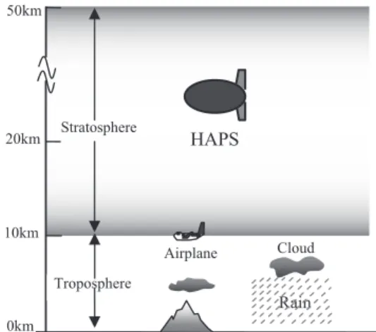
Figure 1 shows the first two layers of the Earth’s atmosphere. The lowest one is the troposphere layer
followed by the stratosphere. UAV, if configured like stationary HAPS, should also stay at an altitude where the wind speed is as low as it is for the layer for HAPS. The average wind velocities are reported in [10]. There is low average wind speed for HAPS at the altitude of 17-22 km but similar wind velocity can also be achieved at the altitude of 3-5 km in troposphere. Therefore, we propose that UAV should stay between the altitudes of 3-5 km.
2.2 UAV Range
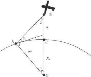
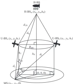
Since HAPS and UAV share similar characteristics, it is first important to look at the system geometry of UAV before we evaluate its communication characteristics. Figure 2 describes the geometry of the UAV system by involving the Earth’s curvature. UAV is positioned at an altitude h (point B) with the sub-platform point C, vertically below the intended UAV location. Point A denotes the position of a user served by the UAV having elevation angle α. Point O represents the Earth’s center and Re is the Earth’s radius.
From the principle of trigonometry, it is expressed as [11]
Assuming the Earth’s surface is perfectly spherical, the arc AC indicates the radius (Ru) of UAV coverage on the ground and might be expressed through the following equation
Let us consider the triangle OAB. The total angle of the triangle is 1800 so that the angle γcan satisfy this equation
After substitution of (2) to (4), we are able to rewrite the diameter, d, of the UAV coverage in (5) as follows[11]
10km 20km 50km
Rain Troposphere
0km
Airplane Cloud
HAPS
Stratosphere
Fig. 1 The first two layers of the earth’s atmosphere.
Figure 3 shows the result of calculating the diameter of UAV coverage at an altitude of 3 km and HAPS at 20 km for a comparison. The figure examines that at very high elevation angles, i.e., 80 deg, the altitude does not affect coverage radius. However, at lower elevation angles, UAV can offer smaller coverage than HAPS. This means that to achieve the same elevation angle, HAPS can provide wider coverage than UAV. Thus, to have high elevation angle coverage by UAV, the cell radius must be small.
Therefore, the UAV system requires multiple base stations to be deployed in a large area but ultimately provides robust communications.
3 Proposed HAPS and UAV Diversity
As UAV is expected to improve system capacity in the urban areas, its cell coverage must not be too great. The greater the cell radius, the lower the elevation angles will be achieved. Therefore, UAVs should offer a relatively small coverage with high elevation angles for all ground terminals under its footprint. To offer complete coverage within an
urban area, multiple UAVs, like terrestrial base stations, are stationed close to each other. This will create UAV diversity.
We also propose a joint system between HAPS and UAVs.
HAPS will either provide supplementary coverage or cover black holes in the UAV footprint. This sort of joint system is expected to offer seamless handover and flawless coverage.
3.1 UAV and HAPS Diversity
The proposed joint system between UAVs and HAPS is called “UAV/HAPS Diversity”. Figure 4 shows the conceptual system of UAV/HAPS Diversity. In this figure, the UAV cell radius is small in order to achieve high elevation angle for its ground terminals to avoid frequent shadowing situation. The number of UAVs depends on the minimum elevation angle we wish to achieve and the service areas to be covered. Furthermore, the larger the service areas to be covered, the more UAV base stations to be deployed as depicted in Fig. 4. Such diversity is expected to improve system capacity within UAV coverage. Also as shown in Fig. 4, HAPS is stationed just above the UAV diversity to supply services to supplement UAV coverage as well as to area not covered by UAVs.
3.2 Proposed System Model
In the future, and especially in urban areas, it is expected that multimedia or Internet applications will be used extensively over the mobile communications.
The introduction of ubiquitous communications will also require seamless communication at anytime and anywhere. Therefore, data traffic will concentrate on one cell. As UAV takes advantage over both terrestrial and HAPS or satellite communication, when it is deployed, its cell coverage must ensure that the data traffic within its coverage will be provided with service quality. For this reason, UAV cannot provide extensive coverage at low elevation angle. Otherwise, the MSs located within the cell edge will experience poor communications. This is due to the large number of MSs covered by one base station and Fig. 3 Diameter of coverage area vs. elevation angle
of UAV and HAPS.
Elevation angle [deg]
Diameter [km]
Fig. 4 UAV/HAPS diversity.
H-BS
U-BS
A
O B
C Re
Re β h α
γ
Fig. 2 Geometrical parameters in UAV ommunication.
to the shadowing condition from the low elevation angle it can achieve at the edge. Therefore, we propose the system model as shown in Fig. 5.
In Fig. 5(a), it is assumed that UAV base station (U- BS) coverage is very large and can accommodate many MSs under its footprint. The MSs located at the cell edge also experience only low elevation angles. This creates a high probability of shadowing condition when U-BS is stationed in urban areas where there are tall buildings. To solve this problem, U-BS needs to cover only a relatively small area with a higher probability of a high elevation angle for all MSs as shown in Fig. 5(b). This solution will help to reduce the number of MSs within one U-BS and help create the probability of LOS condition between MSs and U-BS.
The minimum elevation angle to be achieved by a UAV base station depends on its terrestrial environment characteristics, which vary from city to city. If there are a large number of tall buildings in its service areas, it is necessary to achieve higher minimum elevation angles than for areas with low buildings. To understand this, we need to know the visibility condition based on each elevation angle in a service area.
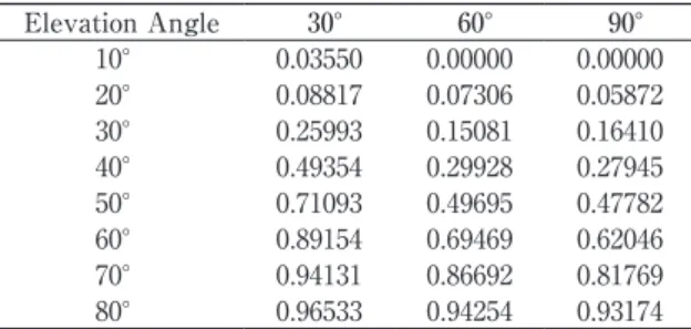
Table 1 shows the visibility of the Shinjuku area of Japan at different elevation angles from 10 deg to 80 deg and at different azimuth angles of 30 deg, 60 deg, and 90 deg [6]. Table 1 suggests that it is difficult to achieve high visibility of more than 50% if the elevation angles fall below 60 deg for azimuth angles of 60 deg and 90 deg. However, for an azimuth angle of 30 deg, more than 70% of visibility can be achieved if the elevation angle is more than 50 deg.
To achieve high visibility in this area, a minimum elevation
angle of at least 50 deg or 60 deg must be maintained. To significantly improve the communication performance over the proposed UAV/HAPS diversity, a robust access scheme should be proposed to take advantage of the diversity.
3.3 Proposed Diversity Access Scheme
In this section, we propose cooperative access using shadowing (CAS) scheme. In our previous work [6], directional access using shadowing (DAS) scheme was proposed to combat shadowing attenuation. But this scheme has the limitation that it is able to adapt the technique only when there is visibility from other base stations and constant switching from one base station creates overhead on the system. With directional transmission, DAS is impractical ornot suitable for real-time communications. In contrast, the CAS scheme takes advantage of the diversity among HAPS and UAVs by creating a cooperative technique when MS experiences strong shadowing from the serving UAV base stations. Figure 6 illustrates the CAS scheme by performing cooperative techniques between HAPS and UAV when a MS is experiencing a shadowing situation.
In Fig. 6, all U-BSs and H-BS are connected to the radio network controller (RNC) to perform controlling and monitoring processes among all U-BSs and H-BS and can share the data and transmit signals simultaneously. These connections are called inter-platform links or backhauls and can be realized by either employing directional radio access links or optical links [12], [13]. We chose the radio link for inter-platform communications and between UAV/
HAPS and RNC. RNC is finally connected to the network gateway for outside network connection or PSTN. MS, which experiences a shadowing problem, seeks cooperation from H-BS and combines their signals. This technique can be realized by applying RAKE combining at receiver and is perfectly controlled by RNC [22].
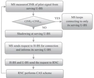
Figure 7 shows the flowchart process of the CAS scheme. First of all, MS, which is connecting to a serving Fig. 5 Proposed system model.
U-BS U-BS
(a) (b)
Table 1 Visibility at different azimuth angles in Shinjuku.
Elevation Angle 30° 60° 90°
10° 0.03550 0.00000 0.00000 20° 0.08817 0.07306 0.05872 30° 0.25993 0.15081 0.16410 40° 0.49354 0.29928 0.27945 50° 0.71093 0.49695 0.47782 60° 0.89154 0.69469 0.62046 70° 0.94131 0.86692 0.81769 80° 0.96533 0.94254 0.93174
Fig. 6 Proposed cooperative access using shadowing scheme.
H-BS
U-BS
Radio Network Controller MS under shadowing of U-BS
U-BS called a “serving U-BS”, measures the CINR of the pilot signal transmitted from its serving U-BS at pilot slots. CINR of the MS is then compared with a required CINR (CINRreq) to judge whether it is under shadowing or not. If the CINR of serving U-BS, CINRU, is less than the CINRreq, the MS is considered to be experiencing a shadowing effect from the physical obstacles under its serving U-BS. The MS then sends a request to H-BS and the serving U-BS to perform cooperation. Both the H-BS and U-BS will coordinate the cooperation process by RNC.
Once the RNC coordination is successful, the MS can transmit and receive signals from both H-BS and U-BS simultaneously. In the meantime, MS keeps measuring its CINR of pilot signal and when the CINR is greater than the required CINR, it sends a request to H-BS to disconnect its connection from the connecting H-BS.
4 Propagation Model and Doppler Shift Effect
The propagation effects that must be accounted for in a UAV channel model are: Propagation model and Doppler shift.
4.1 Propagation Model
As UAV and HAPS share common characteristics, the propagation model of HAPS can also be applied to UAV. UAV is expected to cover urban areas to improve communication capacity. Thus, the urban environment has an impact on its communication channel. It is also important to address this issue and the right propagation mode is needed. In our previous work [7], we proposed a propagation model using a well-known ray-tracing method.
We take into account the building characteristics of service areas to include in the model. The realistic and detailed terrestrial environment has also been accurately defined; channel estimation results can therefore represent
radio propagation characteristic of the area. We intend to employ our previously proposed propagation channel to both UAVs and HAPS and we also include the environment characteristics of an urban area of Japan in our simulations.
To achieve this, we also use the building distribution model and database developed in the previous work.
First of all, we take into consideration the shadowing effect from building heights. It is assumed that the knife- edge diffraction model can be applied to an estimation of building shadowing [14].
Figure 8 illustrates the example of a building model as a protrusion on knife-edge diffraction. MS is assumed to travel parallel to the edge screen which represents street level. Therefore, as it moves past the buildings, a knife-edge diffraction model is applied throughout its path.
The electric field arriving at the MS by way of diffraction on the building edge can be expressed as
where -E0 is the emitted electric field strength at the transmitting antenna, Fd(u) and Fd (v) are called diffraction factor in dimensionless variable u and v, whose detailed description and calculations are described in [7]. The detailed relationship among other variables shown in Fig. 8 is explained in [7]. The relationship enables us to derive the results as a function of elevation angles and azimuth angles.
In addition to the diffraction model, we also consider various rays such as direct rays, and reflected rays. These kinds of ray will contribute to the prediction of received field strength at MS. The electric field from a direct ray arriving at a mobile station can be calculated as follows [15]
where k=2π/λ is propagation constant, -E0 is the emitted electric field strength at the transmitting antenna, Ka is the atmospheric absorption loss.
Fig. 7 Process to perform cooperative access using shadowing scheme.
YES NO MS measuresCINR of pilot signal from
serving U-BS
CINRU>CINRreq
MS keeps connecting to only
its serving U-BS Shadowing at serving U-BS
MS sends request to H-BS for connection and informs its serving U-BS
H-BS and U-BS send the request to RNC
RNC performs CAS scheme
Fig. 8 Geometry model among MS, UAV/HAP and buildings.
MS
UAV/HAPS
D hMS φ
α hb
W1 W2 W3
x x0 x2
d2
d1
h P
φ' Street Direction
The electric field of refracted ray can be obtained by
where d and d’ are the distance between the transmitter and the reflected point and between the reflected point and the receiver, respectively. -R is the Frasnel dyadic reflection coefficient when the incident ray arrives on a dielectric plain surface. -R can be calculated as
where θ, , , and are the incident angle, unit vectors perpendicular to the plain of incidence and the unit vectors parallel to the plain, respectively. ε is the complex dielectric constant. By assuming the building wall and rooftop on which reflected rays occur is a concrete structure, their complex dielectric constant can be set to be ε=3 [16].
However, for ground reflection on the street surface, the complex dielectric constant is defined as ε=15. In addition, Kr is the compensation coefficient for the reflection loss at the reflected point. Although the reflection loss depends generally on the incident angle, Kr is assumed to be -8dB [17].
Finally the total electric field at MS (i.e., diffracted, directed and reflected) can be calculated as
The terrestrial environments for UAV and HAPS must be determined in order to apply to the propagation model and to the diversity techniques in Sec. 3. Hence, we use the building characteristics of an urban region in Japan:
Shinjuku city.
Table 2 denotes the average building height and density of the Shinjuku city [3]. The table shows that Shinjuku city has an average building height of 25.5 m and a density of 290 buildings/km2 considered as an urban area.
The building database for calculations is developed from our building distribution model [7]. In addition to using the building database for the ray-tracing model, it is also important to apply it to the proposed UAV/HAPS diversity.
We assume that UAV base stations are stationed above urban area of Japan and we therefore take into account the building characteristics of this area in Tokyo.
4.2 Doppler Shift Effect
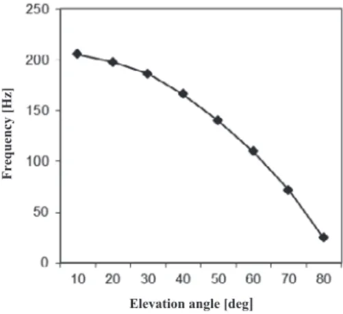
UAVs can be stationery like HAPS or can be moving aerial vehicle. The position of UAVs can change according to time and speed. The well-known Doppler shift effect-the frequency shift experienced by radio signal when either the transmitter or receiver is in motion-needs to be taken into consideration. Figure 9 illustrates the Doppler shift effect between moving UAVs and the MS terminal in terms of elevation angles and azimuth angles [14]. Figure 10 shows the Doppler shift effect as a function of elevation angles [21].
The Doppler shift effect is observed to change according to elevation angles. The higher the elevation angle, the higher the frequency shifts occur. To derive our simulation results based on the elevation angle, different Doppler shift effects at each elevation angle are used differently.
The effect of the Doppler shift can be compensated for by some techniques. To reduce the effect of Doppler shift, sub-carrier spacing can be made wider than the maximum Doppler shift frequency to ensure there is no inter symbol interference (ISI).
Table 2 Average building height and density.
Area Average building height [m]
Building density [buildings/km2]
Shinjuku 25.5 290
Fig. 9 Geometry model of Doppler shift effect.
Fig. 10 Doppler shift vs elevation angle.
VMS
UAV VUAV
MS
φ α
Frequency [Hz]
Elevation angle [deg]
5 Interference Geometrical Analyses
Our objective is to evaluate the proposed system described earlier. Since our proposed diversity consists of multiple UAVs and HAPS, interference analyses should be considered and included in the evaluations.
In Fig. 11, an interference geometrical model among the UAVs and HAPS base station is proposed. Multiple HAPS interference was modelled by [18] but in our proposal, it is enhanced by considering two layers of platforms: a UAV layer and a HAPS layer. In Fig. 11, the MS is moving in the coverage area of UAVs and HAPS suffer interference from both U-BSs and H-BS.
We derive the downlink carrier-to-interference-plus- ratio (CINR) caused by the interference from neighbouring U-BS and H-BS. In this scenario, we assume that one H-BS is stationed in the centre of the coverage area of U-BS as a supplement to the coverage area of U-BS and outside the U-BSs’ coverage. But the U-BS constellation consists of N U-BSs. By denoting the main U-BS by subscript n and n-1, U-BSs and an H-BS is the interfering base stations, the CINR at any point (x, y, 0) on the coverage area can be calculated as [18]
where Pn is the transmission factor. This factor can be obtained from our propagation model in Sec.4.
By considering this, we take into account the shadowing effect from buildings to the MS. NF is the thermal noise floor. Aj(φj) is the antenna gain of the corresponding U-BS and H-BS at an angle φj away from the boresight.
From Fig. 11, the distance link (da, db, dm), between MS to U-BSa, U-BSb, and H-BS, can be expressed as
where (xa, ya, hU), (xb, yb, hU), (xMS, yMS, hH) are the coordinates of U-BSa, U-BSb and H-BSm respectively. hU
and hH are altitudes of UAVs and HAPS respectively.
The angle between U-BS and H-BS, i.e., U-BSa
and H-BSm , U-BSb and H-BSm as seen by MS can be calculated as
where
where
AMS (θa,m), and AMS (θb,m) are the gains of user antenna at angle θa,m and θb,m away from the boredsight and can be expressed by [19]
where φMS is the antenna boredsight gain, sf is a flat side lobe floor, and i is the rate of power rolloff of the main lobe.
6 Performance Evaluations
6.1 Simulation Model and Methodology
The simulated system is assumed to consist of seven U-BSs with radius RU =3 km and an altitude of 3 km and one H-BS with radius RH =30 km and an altitude of 20 km.
The seven U-BSs are arranged in a cell-like environment as shown in Fig. 12. However, H-BS is assumed to cover all the coverage area served by the 7 U-BS as well as the
Fig. 12 Cell model.
U-BS coverage
H-BS coverage Fig. 11 Interference geometrical model.
U-BSb (xb , yb, hU) RHU
H-BSm (xm ,ym,hH)
θa,m
da
dUH
θb,m
C (0, 0, 0)
MS (xms ,yms,0)
hH db
hU
U-BSa (xa ,ya,hU) dm
H-BS
(13)
(14) (15) (16)
(17)
(18)
(19)
(20)
(21) (22)
remaining area outside U-BS coverage and to be stationed at the centre of the cell coverage of U-BS. When the H-BS cell radius is set to 30 km, it provides complete coverage for the seven U-BS cells. U-BS is assumed to be moving at a constant speed and always covers the area within the coverage area of H-BS as illustrated in Fig. 12.
We derive the CINR at different elevation and azimuth angles from any MS moving in the coverage area of U-BSs and H-BS by applying the transmission factor from different elevation and azimuth angles achieved from Sec. 4 to CINR calculation in Sec.5. The achieved CINR is then compared with the CINR threshold, CINRReq, to perform the CAS scheme as described in Sec. 3.3. The detailed simulation parameters are listed in Table 3.
In addition, each MS is assumed to generate packets randomly and independently. The package generation is assumed to follow the Exponential Distribution. Each packet consists of W symbols. A packet is received correctly and successfully only if during the packet transmission period, CINR of each symbol is larger or exceeds the required CINR. Therefore, a successful packet reception, which is called “the achievable packet” in this paper, is achieved when all the symbols in the packet have survived and successfully detected during the transmission period of the packet. We have derived the achievable packets during the simulation time and then calculated the success rates of the achievable packets, which is called “achievable packet rate”.
The traffic to be simulated is considered in terms of
“number of users” and “traffic load.” Traffic load is the total quantity of the packets that include newly generated packets and retransmissions at MS. The normalized offered traffic by a transmission data rate is called G. If the transmission data rate is R (bps) and Ti (bit) is requested to transmit, G =Ti /R [23]. If no packet is generated, G=0. 6.2 Simulation Results and Discussions
We first evaluate our system performance of the proposed diversity technique by means of the achievable packet rate as a function of the number of users.
Figure 13 exhibits the result of the achievable packet rate of each elevation angle from 10 deg to 80 deg as a function of the number of users from 10, 50, 100 to 150. We compare our system “with and without UAV diversity” at RU =3 km.
The dotted lines represent the achievable packet rate angle for “without diversity”. For the sake of paper presentation, we choose to draw only the elevation angles of 10 deg, 30 deg, 60 deg and 80 deg. However, other elevation angles such as 20 deg, 40 deg, 50 deg and 70 deg are also calculated and they follow the same trend.
The achievable packet rate for the system “with diversity” is observed to increase according to the number of users. But in the “without diversity” system, the achievable packet rate starts dropping when the number of users increases to 100 and 150. In the “with diversity” system, each UAV is designed in such way that it does not accommodate too many users. In other words, although the number of user increases, the burden of traffic can be shared among other UAV base stations, thereby allowing each UAV base station to handle the heavy traffic easily. In contrast, when there is no diversity, one UAV base station cannot accept too many users per base station. Thus the achievable packet rate starts to decrease when the traffic from users become heavy. We further compare the result of
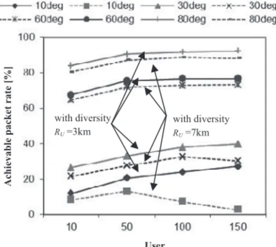
“with diversity” at different cell radii. Figure 14 shows the performance of the achievable packet rate with diversity technique but at different UAV cell radii of RU =3 km and RU =7 km. The result of diversity with a cell radius of RU =3 km is from Fig. 13 and we additionally derive the result of cell radius RU =7 km for a comparison.
It is apparent that when the number of users increase, i.e., at elevation angles of 60 deg and 80 deg, the achievable packet rate for RU =7 km follows the same trend to the achievable packet rate of RU =3 km. However, the trend changes at low elevation angles. For instance, at 30 deg, the achievable packet rate decreases when users increase to 150. Moreover, at 10 deg, the achievable Table 3 Simulation parameters
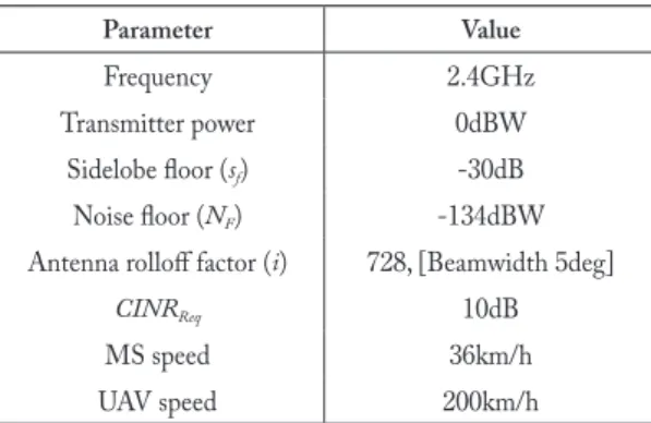
Parameter Value
Frequency 2.4GHz
Transmitter power 0dBW
Sidelobe floor (sf) -30dB Noise floor (NF) -134dBW Antenna rolloff factor (i) 728, [Beamwidth 5deg]
CINRReq 10dB
MS speed 36km/h
UAV speed 200km/h
Fig. 13 Achievable packet rate with and without UAV diversity.
w.o diversity with diversity
User
Achievable packet rate [%]
packet rate starts to drop when users increase to 100 and 150. This is due to the fact that when the cell radius is large and when the user angle becomes low, the visibility state becomes less achievable. When there is heavy traffic happening at such state, the channel impairments have a strong impact on the communication links, making the packets drop accordingly.
We next derive the result from the diversity technique under the CAS scheme as shown in Fig. 15 and Fig. 16. The achievable packet rates are calculated as a function of elevation angles from 10 deg to 80 deg with a 10 deg increment at the azimuth angle of 30 deg, as shown in Fig. 15 and 60 deg, as presented in Fig. 16. From Fig.
15, it is seen that the achievable packet rates increase as the elevation angle becomes higher. For example, at the elevation angles of 10 deg, 20 deg, 30 deg and 40 deg the achievable packet rates are less than 60%. This is because as a result of the high-rise buildings, the elevation angles from 10 deg to 40 deg can achieve visibility of less than 50%, resulting in a high shadowing effect from the building heights. In contrast, elevation angles from 50 deg to 80 deg, can achieve higher packet rates of more than 90%.
It is also observed that performance of achievable packet rates between azimuth angle of 30 deg and 60 deg is also different.
The achievable packet rate for 30 deg azimuth can provide a better performance than a 40 deg elevation angle. This is due to the visibility of the two azimuth angles also being different. Recall from Table 1, the data also explain that the visibility of 30 deg azimuth is better than 60 deg. HAPS/UAV diversity with CAS scheme is also observed to provide a better performance than without the CAS scheme and such enhancement can be explicitly seen at very low elevation angles for the two results of Fig. 15 and Fig. 16. The CAS scheme works very well at low elevation angles when the CINR is lower than the CINR threshold or when the received signal is
low and thus the combined signal can be obtained from both UAVs and HAPS. Such combination can enhance the performance of any user experiencing long and strong shadowing. However, the performance of “with CAS” and “without CAS” is almost the same at high elevation angles because the CAS scheme is not frequently invoked, thereby yielding a similar performance.
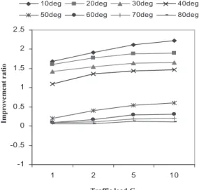
To study the improvement of the CAS scheme, we calculate the improvement ratio at different traffic loads for the elevation angles from 10 deg to 80 deg for further verification. To achieve this result, we derive the achievable packet rates by offering a traffic load from G=1, G=2, G=5 and G=10“with CAS” and “without CAS” scheme.
We then calculate the improvement ratio between the achievable packet rate of “with CAS” and “without CAS”.
Figure 17 illustrates the improvement ratio at different elevation angles. It can be seen from Fig. 17 that the improvement ratio is much higher for low elevation angles, i.e., 10 deg, 20 deg, 30 deg, and 40 deg when the traffic load, G, increases. But at high elevation angles, i.e., 50 deg, 60 deg, 70 deg and 80 deg, the improvement ratio is less 0.5 when the traffic load, G, increases.
Fig. 15 Achievable packet rate of UAV diversity with the CAS scheme, azimuth angle =30 deg.
Fig. 16 Achievable packet rate of UAV diversity with the CAS scheme, azimuth angle=60 deg.
Elevation angle [deg]
Achievable packet rate [%] Achievable packet rate [%]
Elevation angle [deg]
Fig. 14 Achievable packet rate of UAV diversity with different cell radii.
with diversity RU =7km with diversity
RU =3km
User
Achievable packet rate [%]
7 Conclusions
The proposed UAV/HAPS diversity to improve communication capacity when the two systems are deployed together has been presented. To design and evaluate a complete system, interferences among UAVs and HAPS base station are also considered by proposing geometrical interference analyses. This sort of system can be enhanced by cooperative access using shadowing (CAS) scheme to make use of the integrated UAV-HAPS communications.
The UAV/HAPS diversity technique has shown that capacity can be improved by allowing UAV base stations to cover not too many MSs or ensuring their area of coverage is not too great. This sort of technique can help to reduce communication congestion when there are numerous communications links or large volume of traffic, especially in urban area. It is also suitable for urban area where high- rise buildings could be major communication problems on its paths. Finally, the scheme can offer improvement to MSs that suffer strong shadowing effects by buildings or other physical structures by offering combined signal technique to improve its signal strength to low elevation angles. This allows MSs to be able to stay connected with high capacity at all times.
References
[1] D. Grace, N.E. Daly, T.C. Tozer, A.G. Burr, and D.A.J. Pearce,
“Providing multimedia communication from high altitude platforms,” Intern. J. Sat. Commun., vol.19, no.6, pp.559-580, Nov. 2001.
[2] T.C. Tozer and D.Grace, “High altitude platforms for wireless communications,” IEE Electronics and Communication Engineering Journal, vol.13, no.3, pp.127-137. June 2011. [3] M. KONG, O. Yorkinov, S. Shimamoto, “Evaluations of urban
shadowing characteristics for HAPS communication,” Proc.
IEEE CCNC’8, pp.555-559, Jan. 2008.
[4] Iskandar and S. Shimamoto, “Prediction of path loss for stratospheric platforms mobile communications in urban LOS/NLOS environment,” Proc. IEEE ICC’06, vol.12,
pp.5643-5648, June 2006.
[5] T.D. Ho, J. Park, and S. Shimamoto, “Novel Multiple Access Scheme for Wireless Sensor Network Employing Unmanned Aerial Vehicle,” Proc. IEEE/AIAA 29th Digital Avionics System Conference (DASC), Salt Lake City, Utah, Oct. 2010. [6] T. Mikoshiba and S.Shimamoto, “Proposal and evaluation
of communication schemes for mobile systems employing stratospheric aircraft,” IEICE Trans. vol.J83-B, no.5, pp.666- 676, May 2000.
[7] M. KONG, O. Yorkinov, S.Shimamoto, “TCP/IP Performance Evaluations Based on Elevation Angles for Mobile Communications Employing Stratospheric Platform”, IEICE Trans. Comm., vol.E92-B, no.11,pp.3335-3344, Nov.
2009.
[8] A.K. Mitra, “Position-Adaptive UAV Radar for Urban Environment” IEEE Conference on Rada, pp.303-308, Sep.
2003.
[9] T.C Tozer, D. Grace, J. Thompson, P. Baynham, “UAVs and HAPs-potential convergence for military communications,” IEE colloquium on military satellite communications, pp.1-6, Aug. 2002.
[10] J. Thornton, D. Grace, C. Spillard, T. Konefal, and T. C. Tozer,
“Broadband communications from a high altitude platform:
The European helinetprogramme,” IEE Electronics and Communication Engineering Journal, vol.13, no.3, pp.138- 144, Jun. 2001.
[11] A.A. Zavala, J.L.CRuiz, J.A.DPenin, “High-altitude platform for wireless communications,” Jonh Wiley and Sons, Ltd, 2008.
[12] F. Fidler,M. Knapek, J.Horwath, W.R.Leeb, “Optical communications for high-altitude platform,” IEEE Trans. on Quantum Electronics, vol.16, no.5, pp.1058-1070, May 2010. [13] E. Cianca, R. Prasad, M. De Santis, A. D. Luise, M. Antonini,
D. TeoTino, and M. Ruggieri, “Integrated satellite-HAP systems,” IEEE Commun. Mag., vol.42, no.12, pp.33-39, 2005.
[14] F.P.Fontan and P.M. Espineira, Modeling the wireless propagation channel, Jonh Wiley & Sons, 2008.
[15] K. Kimura and J. Horikoshi, “Prediction of millimeter- wave multipath propagation characteristics in mobile radio environment,” IEICE Trans. Electron., vol.E82-C, no.7, pp.1253-1259, Jul. 1999.
[16] H.L. Bertoni, Radio Propagation for modern wireless systems, Prentice Hall PTR, 2000.
[17] A. Satoh and E. Ogawa, “An evaluation method for the reflection coefficient of building walls,” IEICE Transc.
Commm.( Japanese Edition), vol. J72-B-II, no.5, pp207-217, May 1989.
[18] D. Grace, J. Thornton, G. Chen, P. George and T.C. Tozer,
“Improving the system capacity of broadband services using multiple high-altitude platform,” IEEE Trans. Wireless Commun., vol.4, no.2, pp.700-709, Mar. 2005.
[19] J.Thornton, D.Grace, M.H. Capstick, and T.C. Tozer,
“Optimizing and array of antenna for cellular converage from a high altitude platform,” IEEE Trans. Wireless Commun., vol.2, no.3, pp.484-492, May 2003
[20] K. Mori, T.Nagosa, and H. Kobayashi, “Transmission Power Control Based on Predicted SIR for Downlink Channel Transmissions in CDMA Cellular Packet Communications,” IEICE Trans. Commu., vol.E86-B,no.1,pp.96-104, 2003.
[21] K. Lai and M.Cherniakov, “Ray-tracing model of satellite to aircraft communication in aeronautical satellite communication systems,” IEEE TENCOM, 1999.
[22] S.Masumura, M. Nakagawa, “Joint system of terrestrial and high altitude platform station (HAPS) cellular for W-CDMA mobile communications,” IEICE Trans. Commun.,vol.
E85-B, no.10, Oct. 2002.
[23] H. Harada, R. Prasad, Simulation and software radio, Artech House, 2002.
Fig. 17 Improvement ratio of the CAS scheme.
-1 -0.5 0 0.5 1 1.5 2 2.5
1 2 5 10
10deg 20deg 30deg 40deg
50deg 60deg 70deg 80deg
Fig. 17 Improvement ratio of the CAS scheme.
Traffic load G
Improvement ratio