九州大学学術情報リポジトリ
Kyushu University Institutional Repository
炭素溶解反応を伴う溶鉄と炭材間の濡れ挙動の研究
グエン, カオ ソン
https://doi.org/10.15017/1806994
出版情報:Kyushu University, 2016, 博士(工学), 課程博士 バージョン:
権利関係:Fulltext available.
Doctoral Thesis
Study on Wetting Behaviour between Liquid Iron and Carbonaceous Materials
with Carbon Dissolution Reaction
Cao Son NGUYEN
Department of Material Science and Engineering Faculty of Engineering
Kyushu University Japan
2017
Study on Wetting Behaviour between Liquid Iron and Carbonaceous Materials
with Carbon Dissolution Reaction
Study on Wetting Behaviour between Liquid Iron and Carbonaceous Materials
with Carbon Dissolution Reaction
By
Cao Son NGUYEN
Department of Materials Science and Engineering Faculty of Engineering
Kyushu University
Fukuoka, Japan 2017.1.11 Approved by
Prof. Kazuya KUNITOMO
Major Supervisor
Title: Study on Wetting Behaviour between Liquid Iron and Carbonaceous Materials with Carbon Dissolution Reaction
Abstract
Behaviour of liquid phase in the lower part of a blast furnace plays crucial role in operation of the blast furnace. Increasing of liquid flow fluidity can decrease liquid hold-up on the voids in the coke bed, which contributes to improvement of the blast furnace operation. Therefore, correct understanding on liquid flow behaviour is very important to increase productivity and efficiency of the blast furnace. One of the most important factors to affect the liquid flow behaviour is wettability of the coke by liquid phase. Indeed, the wetting behaviour between liquid phase and the coke substrate has been extensively explored; the wettability of coke substrate by liquid Fe-C is considered as a first step to understand the liquid flow behaviour in the blast furnace.
In this study, the wetting behaviour of liquid iron on the substrate is investigated using laboratory experiments. The sessile drop method with molten sample injection system and a novel facility equipped with a quenching system were applied. Liquid Fe-C samples, carbon saturated and unsaturated Fe-C samples, were made from the 99.90% pure iron and 99.90% pure graphite using high frequency induction heating furnace under an inert gas atmosphere. The carbonaceous materials substrate, or simulant coke substrate, was made from 99.90% pure graphite and 99.90% pure Al2O3 using a graphite heating-element hot press furnace under a pure argon gas atmosphere.
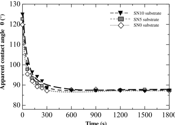
The results shown that the apparent contact angle significantly decreased from
the initial value in the wetting of liquid Fe-C and the substrate. The wetting behaviour of liquid Fe-C sample on the substrate could be divided into two periods.
In the initial contact period, the apparent contact angle significantly decreased with time from the initial value. After this period, the apparent contact angle stabilized at a constant equilibrium value.
Carbon dissolution reaction was confirmed to influence greatly on the wetting behaviour between the liquid Fe-C sample and the simulant coke substrate in this study. The carbon dissolution reaction could make changes in both interfacial morphology and interfacial energy. When liquid carbon saturated Fe-C sample wetted on the substrate, the carbon dissolution amount was not enough to change the interfacial morphology; the liquid Fe-C sample spread on the flat surface of substrate. On the other hand, when the carbon dissolution was enough to make decreases in the interface energy of solid-liquid phases, the apparent contact angle decreased. In the case of carbon un-saturated Fe-C sample wetting on the substrate, effects of carbon dissolution reaction on wetting behaviour were considered. The concave was formed because carbon atoms dissolved from the substrate into the Fe-C sample, which strongly affected the wetting behaviour of liquid Fe-C sample on the substrate. In the initial contact period, the results shown that the decreasing of interfacial energy of solid-liquid phases caused the apparent contact angle to decrease before the formation of concave; the apparent contact angle decreased with decreasing of interfacial energy of liquid-solid phases. On the other hand, the interfacial energy of liquid-solid phases remained constant value when the concave was formed. In this case, the apparent contact angle dominantly depended on interfacial morphology due to carbon dissolution reaction occurred.
In this research, effects of Al2O3 on the wetting behaviour were considered in the
contact between the liquid Fe-C sample and the simulant coke substrate. The amount of carbon dissolution decreased with increasing of Al2O3 content in the substrate. The formation of concave was also confirmed when the substrate contain 10 vol% Al2O3 or less; the apparent contact angle in the initial contact period decreased with decreasing of Al2O3 content. However, there was no obvious different apparently equilibrium contact angle in this case. Additionally, the formation of Al2O3 layer was confirmed at the interface area when the substrate content 20 vol% Al2O3 in the substrate. The accumulation of Al2O3 in the interfacial region was reasonable to cause the imbalance of interfacial energy at the triple line, which increased the apparent contact angle.
1
Contents
Contents………... 1
List of Caption………. 4
Chapter 1. Introduction………. 8
1.1 Introduction………... 8
1.2. Thesis objectives……….. 13
Chapter 2. Background……..……… 15
2.1. Blast furnace process……….………... 15
2.2. Role of the melts in the blast furnace operation……… 17
2.2.1 Cohesive zone………... 17
2.2.2 Dripping zone……….. 18
2.2.3 Deadman………... 19
2.3. Wetting at high temperature between liquid metal and solid phase……… 20
2.3.1. Non-reactive wetting………... 20
2.3.2. Reactive wetting………... 21
2.3.2.1. Dissolution wetting………... 21
2.3.2.2. Formation of a new compound at the interface……… 24
Chapter 3. Experimental method………….………... 27
3.1. Experimental materials………. 27
3.1.1 Fe-C samples………. 27
3.1.2 Simulant coke substrates……… 28
2
3.2 Experimental procedure………. 30 3.2.1 Sessile drop method with molten sample injection
system………. 30
3.2.2 Sessile drop method with molten sample injection and
quenching systems………. 32
Chapter 4. Results and Discussion……… 34 4.1 Wetting behavior of simulant coke substrate by Fe-C sample………… 34
4.1.1. Measurement results of contact angle of carbon saturated Fe- C sample on simulant coke substrate………. 34 4.1.2. Apparent contact angle results of reactive wetting between carbon-unsaturated Fe-C sample and simulant coke
substrate………. 36
4.2 The Fe-C samples wetting on the substrate in the initial contact
period………... 39
4.2.1 Factors affecting the initial contact angle value……… 39 4.2.2 Apparent contact angles variation with time in the wetting between the Fe-C samples and the substrate in the initial contact
period……… 46
4.2.3. Effect of carbon dissolution on the wetting of Fe-C sample on the graphite substrate in the initial contact period………. 49 4.2.4 Role of Al2O3 in wetting behaviour of the Fe-C sample on simulant coke substrate in the initial contact period………. 63 4.3. Wetting behaviour between the carbon Fe-C sample and the substrate
in the constant stage..………. 71
3
4.3.1 The carbon saturated Fe-C sample wetting on the
substrate……….. 71
4.3.2. Reactive wetting behaviour between carbon-unsaturated Fe-C sample and simulant coke substrate in the constant stage... 75
4.3.3. Role of Al2O3 in the reactive wetting behaviour with concave formation in the contact stage………..………... 83
Chapter 5. Summary……….. 86
5.1. Proposing future work………... 86
5.2. Conclusions……….. 87
References……… 90
Acknowledgements……….. 93
4
List of Caption Tables
Table 1. Carbon composition of Fe-C samples used.
Table 2. Physical properties of simulant coke substrate.
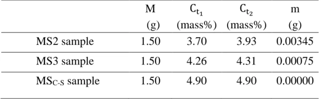
Table 3. Amount of carbon dissolution in time period of movement of Fe- C/graphite assembly and quenching process.
Table 4. Initial interfacial energy and initial apparent contact angle in the wetting between the Fe-C samples and the substrate.
Table 5. Variation of radius and height of the concaves in wetting of carbon- unsaturated Fe-C samples on graphite substrate.
Table 6. Dihedral contact angle variation with time in wetting of carbon unsaturated Fe-C samples on graphite substrate.
Table 7. Variation of the interfacial energy with time between Fe-C sample and graphite substrate.
Table 8. Amount of carbon dissolution transferred from graphite substrate into carbon saturated Fe-C sample.
Table 9. Initial interfacial energy of solid-vapour and solid-liquid phases.
Table 10. Dihedral contact angles and interfacial energy values between the iron samples and the substrates in the constant stage.
Figures
Fig. 1. The blast furnace process.
Fig. 2. The non-reactive wetting between liquid and solid phases.
Fig. 3. Schematic of geometry at the triple line position.
Fig. 4. Stable configuration of formation of interfacial layer.
Fig. 5. Metastable configuration of formation of interfacial layer.
5
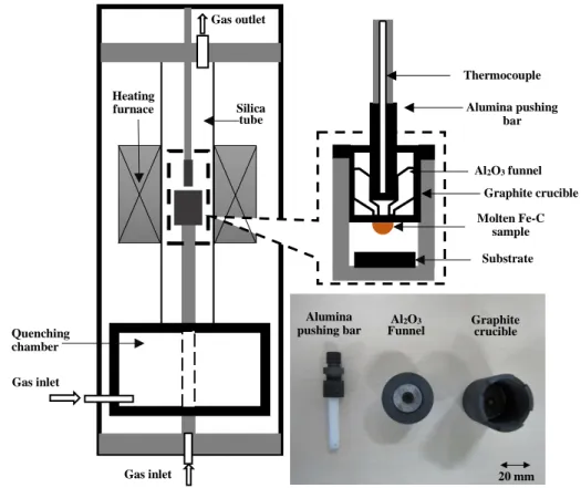
Fig. 6. Schematic of sessile drop method with molten sample injection system.
Fig. 7. Sessile drop method with molten sample injection and quenching systems.
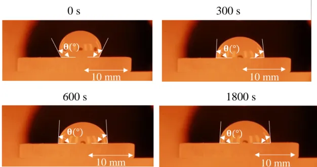
Fig 8. Images of droplet spreading on the substrate at different moment.
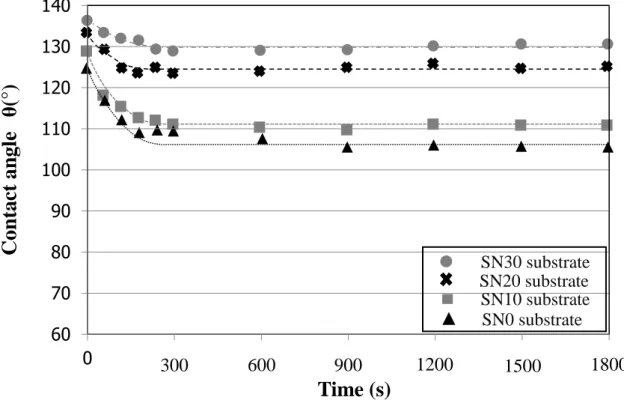
Fig. 9. Effect of Al2O3 content on wettability of the MSC-S sample on the simulant coke substrates at 1673 K.
Fig. 10. Apparent contact angle variation in wetting of MS1 Fe-C sample on simulant coke substrate.
Fig. 11. Apparent contact angle variation in wetting of MS2 Fe-C sample on simulant coke substrate.
Fig. 12. Apparent contact angle variation in wetting of MS3 Fe-C sample on simulant coke substrate.
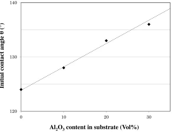
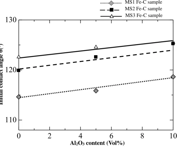
Fig. 13. Effect of Al2O3 content in substrate on initial contact angle of the MSC-S. Fig. 14. Variation of initial contact angle with amount of Al2O3 in the substrate for different Fe-C samples.
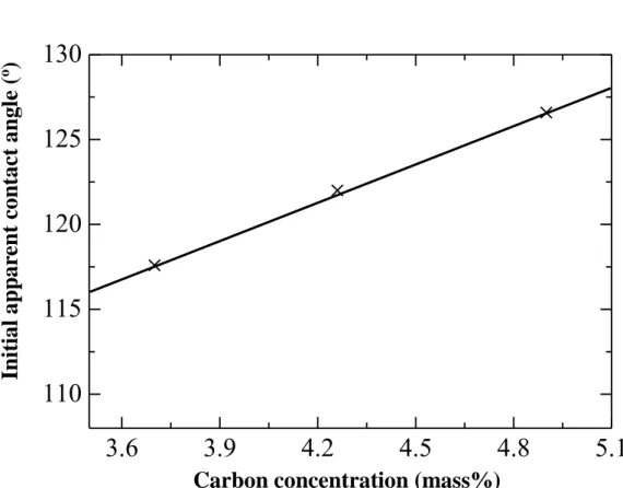
Fig. 15. Relationship between initial carbon concentration of Fe-C sample and initial apparent contact angle.
Fig. 16. Relationship between carbon dissolution amount and initial interfacial energy of solid-liquid phases.
Fig. 17. Variation of apparent contact angle with time in the initial contact period using sessile method with molten sample injection system.
Fig. 18. Images of cross-sections of quenched Fe-C/graphite assemblies.
Fig. 19. Variation of apparent contact angle with time in the initial contact period using quenching system.
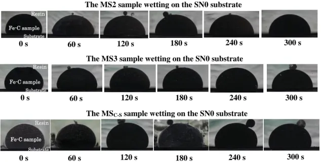
Fig. 20. Interfacial phenomena of MS2 sample wetting on graphite substrate.
Fig. 21. Interfacial phenomena of MS3 sample wetting on graphite substrate.
6
Fig. 22. Interfacial phenomena of MSC-S sample wetting on graphite substrate.
Fig. 23. Schematic illustration of the spherical cap.
Fig. 24. Variation of concave volume of carbon-unsaturated Fe-C samples with time in the initial contact period.
Fig. 25. Variation of carbon concentration of Fe-C samples with time in the initial contact period.
Fig. 26. Schematic illustration of geometry at the triple line position.
Fig. 27. Variation of interfacial energy of solid-liquid phases with time of the MS2 Fe-C sample wetting on the SN0 substrate in the initial contact period.
Fig. 28. Variation of interfacial energy of solid-liquid phases with time of the MS3 Fe-C sample wetting on the SN0 substrate in the initial contact period.
Fig. 29. Contact angle variation with time in the reactive system according to the model of Aksay et al.41)
Fig. 30. Interfacial phenomena of the MSC-S wetting on the SN0 substrate.
Fig. 31. Changes in amount carbon dissolution and solid-liquid interfacial energy of MSC-S in the initial contact period.
Fig. 32. Images of cross-sections of the cooled Fe-C/simulant coke assemblies.
Fig. 33. Variation of apparent contact angle with time in the wetting of MS2 Fe-C sample on the SN0, SN10 and SN 20 substrates in the initial contact period.
Fig. 34. Variation of carbon content with time in the wetting of MS2 Fe-C sample on the SN0, SN10 and SN 20 substrates in the first 300 s of contact period.
Fig. 35. Interfacial phenomena of Fe-C sample with MS2 Fe-C sample wetting on SN20 substrate.
Fig. 36. Al2O3 powder distribution in the contact region between Fe-C sample and the SN20 substrate after the first 240 s of contact period.
7
Fig. 37. The movement of triple line in the wetting of MS2 on the SN20 substrate Fig. 38. Optical micrographs of the cooled sample’s interfaces.
Fig. 39. Estimation of carbon dissolution amount from the optical micrograph at the interface.
Fig. 40. Relationship between amount of carbon dissolution and interfacial variations.
Fig. 41. Relationship between amount of carbon dissolution and contact angle variation from the initial contact angle to the constant contact angle.
Fig. 42: Optical microscope images of concave formation at the interface area between SN10 substrate and (a) MS1, (b) MS2, and (c) MS3 Fe-C samples.
Fig. 43: Optical microscope images of concave formation at the interface area between MS1 Fe-C sample and (a) SN0, (b) SN5, and (c) SN10 substrates.
Fig. 44. Estimation of carbon dissolution amount from the optical micrograph at interface.
Fig. 45. Relationship between Al2O3 amount in the substrate and carbon dissolution amount.
Fig. 46. Evaluation of the occupied Al2O3 area on the surface of the simulant coke substrate from image analysis of cross-sectional observations.
Fig. 47. Schematic of geometry at the triple position.
Fig. 48. Relationship between interfacial energy variation and Al2O3 amount in the substrate.
Fig. 49. Relationship between Al2O3 in the substrate and dihedral contact angle.
8
1. Introduction
1.1. Introduction
In a blast furnace, burden (sinter, pellets, lump ore and flux) and coke are separately charged from the top of the furnace, and then descend to the bottom.
During the movement of the burden in the blast furnace, the temperature of the iron ore and the coke are increased due to heat transfer from gases; the iron ore (iron oxides) is reduced by the coke, coal, and reductive gases. These gases, carry heat and reductants, ascend from the lower part of the blast furnace. Once the temperature of burden exceeds the softening temperature of the iron ore, the burden starts softening and melting to form a region called cohesive zone. From the cohesive zone, the melts continue to move downwards to the hearth of the blast furnace. Meanwhile, the coke remains the phase of solid, which is only material existing as solid phase in the lower part of the blast furnace.
The movement of the melts through the coke bed has strong influence on the blast furnace operation. Bando et al.1) reported that increasing of melts fluidity causes the liquid holdup to decrease, and consequently, decreasing the melts ratio in the coke bed. This situation increases the gas permeability1-5) which causes the blast furnace to operate efficiently and stably. In an effort to further improve stable and efficient operation of the blast furnace, behaviour of the melts in the coke bed in the lower part of the blast furnace should be correctly understood. Particularly, in case of low carbon operation in the blast furnace, the blast furnace is operated with decreasing of the coke ratio in order to reduce the CO2 emission exhausting from the furnace. This solution of low carbon operation decreases coke layers thickness in the blast furnace, which makes liquid ratio in the coke layer to relatively increase. Consequently, this way significantly decreases the stability and
9
efficiency of blast furnace due to decreasing of gas permeability.6)
One of the most important properties affecting the melts behaviour is the wettability of the coke by the melts.7-9) Hence, the wetting behaviour of the melts on the coke must be considered in order to clarify the behaviour of the melts in the blast furnace. The melts include liquid Fe-C and molten slag which coexist in the lower part of the blast furnace. In the cohesive zone, the liquid Fe-C is initially produced by reduction reactions from the iron ore burden when they are in contact with the coke and the reductive gases; once formed, together with slag, the liquid Fe-C begins to drip through the coke-packed bed. Own physical properties of the liquid Fe-C and interaction of the molten slag were reported to have strong influence on the movement of the melts through a coke-packed bed.10) Accordingly, role of the molten slag in the wettability of the liquid phase is thought to be also important in these phenomenon. The effect of the molten slag interactions on the wetting behaviour between the iron sample and coke will be studied in the next step as future studies. In this research, the wettability of liquid Fe-C on solid coke is considered as a first step in understanding the melts behaviour in blast furnace operations.
The wetting behaviour between liquid Fe-C and the coke substrate is affected by several factors, such as the structure of carbon, the ash component in coke and the carbon concentration of iron sample.11-18) Ash concentration in the coke and carbon dissolution reaction are reported to be crucial role in the wettability of the liquid Fe-C on the coke substrate because they could affect carbon diffusion process from the coke substrate to the liquid Fe-C.11-14) These effect could change the driving force for the wetting behaviour. Additionally, not only mass transfer from the substrate to the liquid phase but also the interfacial morphology affects
10
the wettability of liquid phase.19) S.T. Cham et al.13) and C. Wu et al.11) reported that the carbon dissolution reaction occurred for liquid Fe-C sample in contact with carbonaceous material. In other words, carbon atoms can transfer from the carbonaceous materials substrate into the liquid Fe-C sample. N. Eustathopoulos et al.20) revealed that transport of dissolving elements in the bulk liquid strongly affected the spreading rate of droplet in dissolutive wetting. Therefore, it is thought that the carbon dissolution reaction strongly influences the wetting behaviour between the liquid Fe-C sample and the substrate. The carbon dissolution reaction at the interface between liquid Fe-C and the substrate may has strong influence on the interfacial energy of solid-liquid phase and/or the interfacial morphology.
These phenomenon have possibility to change by carbon dissolution reaction from the substrate to liquid phase, which can affect the wettability of the substrate with the melts. Effects of the interfacial morphology, the carbon concentration of liquid Fe-C and the ash components in the coke on the wetting behaviour of the coke substrate by the liquid Fe-C are considered in this research thesis. The wetting behaviour between liquid Fe-C sample and carbonaceous materials is investigated using laboratory experiments.
In the previous study, wetting behaviour of liquid Fe-C sample on carbonaceous materials substrate has been commonly investigated using a conventional sessile drop method.10,11,21,22) However, in this method, interactions between the Fe-C sample and the substrate can occur during the heating process. The reactions at the interface between the liquid phase and the solid substrate are thought to initially decrease the interfacial energy.23) Therefore, the measured contact angle values can be affected by the initial reactions. In order to avoid this problem, a sessile drop method with molten sample injection system is used. The Fe-C sample and the
11
substrate are separately heated; the contact angle is measured just after the liquid Fe-C sample drops onto the substrate.
Wetting behaviour of liquid Fe-C sample on carbonaceous materials substrate was confirmed to have two periods.2,11,24,25) The initial contact period reported a significant decrease in the apparent contact angle, meanwhile the value of the apparent contact angle was constant in the late contact period. The initial contact period is indicated to play a crucial role in the wetting behaviour between the liquid Fe-C sample and the carbonaceous materials substrate. Therefore, the initial contact period must be considered to have further understanding about the wetting behaviour of the substrate by the liquid Fe-C sample.
The interfacial morphology in the wetting of the liquid Fe-C sample on the carbonaceous materials substrate is possible to vary by carbon dissolution reaction in the initial contact period. Meanwhile, O. Dezellus et al.26) and N. Eustathopoulos et al.23) reported that the interfacial morphology had strong influence on the wetting behaviour of liquid metal on solid substrate. Therefore, the carbon dissolution reaction may largely influence the wetting behaviour of the liquid Fe- C on the coke substrate with carbon dissolution reaction in the initial contact period.
However, in the previous studies, the results obtained from the sessile drop method with molten sample injection system cannot discuss effects of the carbon dissolution reaction in the initial contact period because a quenching system in the experimental method was not equipped. The quenching system can terminate carbon atoms transferred from the substrate into the liquid Fe-C sample at different moments in the contact period. Effect of carbon dissolution on the interfacial energy and interfacial morphology remained to be clarified.
To correctly understand the effects of carbon dissolution on the wetting
12
behaviour of liquid Fe-C on the substrate in the initial contact period, a novel facility equipped with a quenching system is deployed in this research. This method can instantaneously estimate interfacial morphology and carbon concentration variation in the initial contact period. Besides, in this period, this equipment can determine effects of ash component in the carbonaceous materials on the carbon dissolution reaction and the interfacial morphology.
The aim of this research is to clarify the role of the carbon dissolution reaction in the wetting behaviour of the liquid Fe-C sample on the substrate. Effects of interfacial morphology and interfacial energy variations on the wetting behaviour of the carbonaceous materials substrate by liquid Fe-C sample are considered in this study. Using the sessile drop method with molten sample injection system, the wetting behaviour will be examined; carbon dissolution reaction and ash component affecting the interfacial morphology and the interfacial energy will be evaluated and the effects of the ash components. Additionally, the behaviour of the liquid Fe-C wetting on the coke substrate in the initial contact period is examined through laboratory experiments using the sessile drop method with molten sample injection and quenching systems. This method is to clarify effects of carbon dissolution reaction and the ash component on wetting behaviour of carbonaceous materials substrate by liquid Fe-C sample in the initial contact period. A new knowledge of the fundamental of the reactive wetting behaviour between the liquid Fe-C on the coke substrate is obtained.
13
1.2. Thesis objectives
The contact angles of the Fe-C sample on the substrate were measured using two system, ‘‘the sessile drop method with a molten sample injection system’’ and
‘‘sessile drop method with molten injection and quenching systems’’ at 1673 K.
These method can prevent reactions between the Fe-C sample and the substrate during the heating process to the predetermined temperature. The quenching system allows to estimate effects of carbon dissolution reaction and interfacial morphology on the wetting behaviour of the liquid Fe-C sample on the substrate.
The effect of ash on wettability is necessary to examine. Silica is the main component of ash in coal and coke; however, it is unstable at temperatures exceeding 1873 K because it can react with graphite during the fabrication of simulant coke. In this research, Al2O3 powder was used as ash in the simulant coke because Al2O3, another main component of coke ash, is stable with graphite at 1873 K.
A fundamental knowledge of wetting behaviour between liquid Fe-C and the simulant coke substrate will be obtained in this study. There are 4 objectives will be focused as follows:
1. The wetting behaviour between liquid Fe-C sample and the simulant coke substrate is investigated using new equipments to avoid the interactions during heating process;
2. Effect of simulant ash on the wetting behaviour of carbon unsaturated and saturated Fe-C samples on the simulant coke substrate are evaluated;
3. Role of carbon dissolution reaction in the wettability of the simulant coke substrate by the Fe-C samples is determined;
14
4. Interfacial morphology are observed and carbon concentration variations are estimated in the initial contact period between the Fe-C sample and the coke substrate.
15
2. Background
2.1 Blast furnace process
Liquid iron is commonly produced by blast furnace from iron ore even though this technology has undergone a long history. The blast furnace process still plays a crucial role in the field of ironmaking all over the world. In this process, the counter-current region of burden and gas flows occurs. The gases, carry heat and reductive agents, ascend from the lower part of blast furnace. The iron ore burden and the coke are charged from the top into the blast furnace but the coke is separately charged. The iron ore burden and coke move downwards to the bottom of the blast furnace due to decrease in the material volume, coke burning in front of tuyeres, change in the phase of materials and tapping of liquid phase. The blast furnace process is illustrated in Fig. 1.
Fig. 1. The blast furnace process.
Blast (Air, steam, O2, PCI) Ore
Coke
Deadman
Cohesive zone
Tuyeres
Raceways Hearth
Dripping zone
Slag
Hot metal Tap hole
16
The coke which is the only solid phase existing in the lower part of the blast furnace, is responsible for reduction reaction, heat supplying, gas permeability and carburization of iron. Meanwhile, phase transformation and reduction reaction of the iron ore burden occur when the iron ore temperature increases and the iron ore contacts with the reductive gases and carbonaceous materials. The iron ore burden including iron oxides and gangue minerals is transferred and reduced into liquid iron and molten slag, then the melts pass through the coke bed in the lower part of the blast furnace. Because the density of molten slag is lower than that of the liquid iron, the liquid iron and the molten slag can be separated in the hearth of blast furnace. The liquid iron and molten slag are tapped out through the tap holes.
As mentioned before, the gases carrying heat and reductants are produced from the lower part of the furnace. The hot blast blowing through the tuyeres can react with the coke to form the carbon monoxide in front of tuyeres, as shown in reactions (1) and (2); the coke is a source of both heat and reductive gas. The reductive gases, ascend through the coke bed from this region, are responsible for removal of the oxygen of the iron ore burden.
C+ O2 → CO2 (1) C + CO2 → 2CO (2) 3Fe2O3 + CO → 2Fe3O4 + CO2 (3) 3Fe2O3 + H2 → 2Fe3O4 + H2O (4) Fe3O4 + CO → 3FeO + CO2 (5) Fe3O4 + H2 → 3FeO + H2O (6) FeO + CO → Fe + CO2 (7) FeO + H2 → Fe + H2O (8)
In the blast furnace process, both indirect reduction, as shown in reactions (3) –
17
(8) and direct reduction, as shown in reaction (11) are responsible to create pure liquid iron. The indirect reaction should be improved to decrease energy consumption in the blast furnace process. Because if the degree of indirect reaction is lower, amount of unreduced oxygen of oxides will be higher. This unreduced oxygen will be removed by C as shown in reaction (11) which is endothermic.
FeO + CO → Fe + CO2 (9) CO2 + C → 2CO (10) FeO + C → Fe + CO (11)
Further, an extra amount of carbon burnt at the tuyeres to produce the endothermal heat of direct reaction is lower. The coke rate will decrease by an amount equal to the extra direct reduction and associated extra tuyere carbon.
When liquid iron initially appears in cohesive zone, the liquid iron drops downwards through coke bed in lower part of the blast furnace. During this movement of the liquid iron, the carburization takes place in the contact with carbonaceous materials. The carbon concentration of liquid iron increases and reaches approximately 4.5 mass% before tapping out.
2.2 Role of the melts in the blast furnace operation 2.2.1 Cohesive zone
Temperature of the iron ore increases during descending; once exceeded the softening temperature of the iron ore, the phase of the burden starts softening. The region of softening is formed and it is called cohesive zone as shown in Fig. 1. The temperature of this zone approximately ranges from 1423 K to 1673 K.
Characteristic of the cohesive zone largely affects the blast furnace operation because this zone has strong influence on permeability and flow behaviour of gases.
The shape, location and temperature range of cohesive zone significantly
18
depend on the iron ore burden properties, the temperature distribution in the furnace and other parameters. In order to improve the blast furnace operation, cohesive zone should be mainly controlled by improvement of the iron ore properties and/or temperature distribution in the furnace. For example, increasing of softening and melting temperatures of the burden, the cohesive zone position becomes lower; decreasing range of softening-melting transformation causes the cohesive zone to have narrower thickness of cohesive zone. These solutions can significantly improve permeability of gas, which decrease the pressure drop when the gases pass through the cohesive zone.
Besides, the cohesive zone plays a crucial role in the gas flow distribution through the coke layer. In turn, the cohesive zone may have influence on the solid flow in the upper part of blast furnace. Therefore, the gas flow and hence the furnace productivity are strongly influenced by the shape of the cohesive zone.
2.2.2 Dripping zone
The region that is just below the cohesive zone is called as dripping zone of the blast furnace as shown in Fig. 1. The melts in the cohesive zone go downwards into the dripping zone of the furnace. The movement of the melts in the dripping zone is very important for the stable operation of blast furnace. In this zone, the gases and the liquid flows counter-currently in the slowly moving bed of the coke particles. If the melts reduce the free cross-section area available for the flow of gases, the pressure drop will increase with increasing liquid hold-up.
Liquid hold-up in coke bed includes both static liquid hold-up and dynamic liquid hold-up. Static hold-up is defined as the amount of liquid that remains within the bed’s voids after stopping the flow and generally depends on bed and liquid properties. Dynamic hold-up, also known as operating hold-up, is defined as the
19
liquid that flows out of the bed after stopping the liquid supply.
Increasing of liquid hold-up leads to increase in resistance to gas flow. This situation may be result in liquid hold-up (loading) in the coke voids, which would decrease free volume. Additionally, increasing of pressure drop causes the gas velocity to increase, and consequently, the gases have to bubble through a mass of liquids. Much of the latter, the liquid may be carried upwards mechanically leading to the so-called flooding. However, in order to improve stability and productivity of the blast furnace operation, increasing of liquid fluidity should be considered because increase of liquid fluidity causes the liquid hold-up to decrease. Therefore, the gas pressure drop decreases and gases would smoothly ascend. Consequently, the blast furnace stably and efficiently operates.
2.2.3 Deadman
The deadman consists of mixture of coke with dense molten mass of iron burden, as shown in Fig. 1. This passive zone occupies probably 3-4% of the blast furnace volume. The residence time of materials in the deadman zone is estimated 5 to 10 days. The deadman becomes compact and drainage of the melts decrease when small coke particles exist in this region. To maintain high permeability of the deadman, the fine coke in this zone must be consistently consumed by dripping metal. Coke particles are able to dissolute into the dripping metal.
Dripping metal causes little damage to the deadman coke lumps when metal drains rapidly through the deadman. Because the carbon atoms have little time to dissolve into the liquid metal, the concentration of carbon of the liquid metal has a little increase. Therefore, when the liquid iron arrives in the hearth, it has high carbon adsorption capacity. The liquid iron is able to increase hearth permeability and consume the coke particles. However, when the dripping metal slowly passes
20
through the deadman area, the deadman coke is damaged. In other words, the coke decreases the particle size. Finally, the liquid iron arrives in the hearth zone of blast furnace with low carbon absorption capacity to remove any fines coke particles.
Therefore, the hearth coke bed renewal is retarded.
2.3 Wetting at high temperature between liquid metal and solid phase 2.3.1 Non-reactive wetting
The behaviour of a small droplet on a horizontal and perfectly smooth solid substrate was considered a non-reactive wetting, as shown in Fig. 2. Reactions have not occurred between the liquid and solid phases during the contact period.
In this case, the wettability of the substrate by the liquid phase is evaluated by the value of Young’s contact angle θ(°). The contact angle θ is given by Young’s equation, as shown in Eq. (1).
γSV = γSL+ γLVcos θ (1)
where γSV (J/m2) and γLV (J/m2) are defined as the interfacial energies of the solid-vapour and liquid-vapour phases, respectively. γSL (J/m2) denotes the solid- liquid phases interfacial energy.
Fig. 2. The non-reactive wetting between liquid and solid phases.
Moreover, by measuring the contact angle θ and the interfacial energy of the liquid-vapour, work of adhesion can be evaluated using Eq. (3). It is assumed that
γLV
γSV
γSL θ
21
all the interfaces are isotropic, then by combining Eq. (2) with Young’s equation (Eq. (1)), the Wad can be expressed as a function of the contact angle (the Young- Dupre’s equation), as shown in Eq. (3).
Wad = γSV+ γLV− γSL (2) Wad = γLV(1 + cos θ) (3)
where the Wad (J/m2) is the work per unit area necessary to separate an interfacial energy γSL (J/m2) into two equilibrated surface of energies γSV and γLV (J/m2).
The sessile drop method commonly is used to evaluate the wetting behaviour of liquid phase on solid substrate by measuring the rate of the triple line over the solid surface when the contact angle decrease towards its final equilibrium value, θF. In non-reactive wetting, the droplet is formed by the melting of a small solid piece on the solid substrate. This conventional sessile drop technique faces two difficulties which are to maintain isothermal condition during experimental procedure and to avoid the interactions during the heating up the samples. These issues would affect the precise measurement of contact angles.
This drawback of conventional sessile drop method can be avoided using sessile drop method with molten sample injection system. In this method, the drop and the substrate are heated separately before the liquid phase is brought in the contact with the substrate at a predetermined temperature. However, for both of these arrangement, the spreading process may be perturbed by external forces; the kinetic energy of a droplet transiently increase the driving force for wetting.
2.3.2 Reactive wetting 2.3.2.1 Dissolution wetting
(1) Dissolution-insensitive γLV and γSL values
Reactive wetting of liquid phase on solid substrate at high temperature is
22
considered when composition of liquid phase is pure or un-saturated in element of the solid substrate. In this case, the interfacial energies of liquid-vapour and solid- liquid phases are assumed to maintain constant. The changes in the interfacial morphology would occur. The process contains three stages having different time scales as follows.
Stage 1: Spreading of liquid phase on the solid substrate takes place in a short time t1. During this stage, the effect of dissolution on the macroscopic morphology is negligible. The contact angle until t1 is nearly equal to the Young’s contact angle of the system.
Stage 2: Dissolution process from the solid substrate to the liquid phase occurs, which affects the macroscopic contact angle after a certain time. The changes in interfacial morphology with time were calculated by considering that the microscopic dihedral angle at the triple line is given by Eq. (4) and assuming that the triple line remains on the plane of the substrate.
γSV
sin θL = γSL
sin θV = γLV
sin θS (4)
where γSV, γSL, and γLV (J/m2)represent the interfacial energies of solid- vapour, solid-liquid and liquid-vapour phases, respectively. θL, θV and θS (°) denote the dihedral contact angles, and θL+ θV+ θS= 360°, as shown in Fig.
3.
Moreover, assuming that the transfer of atoms through the interface is rapid compared to diffusion in the liquid alloy, it follows that solid and liquid phases are in thermodynamic equilibrium at the interface. During this time, the depth of the concave in the solid is greater close to the triple line where the comparatively fresh liquid in contact with the solid causes a more rapid dissolution.
23
Stage 3: At much longer time, the shape of the solid/liquid interface will change to form a uniform curvature.
(2) Dissolution sensitive γ𝐿𝑉 and γSL values
The particular case of dissolution is considered when the dissolution is high enough to modify the interfacial energy but small enough to neglect any deviation of the interface. The interface is assumed to be flat. When dissolution does not affect γSVo and γLVo (J/m2) (the superscript 0 denotes the values of these quantities before reaction), the driving force of wetting can be described by Eq. (5) as follows:
fd(t) = γSVo − (γSLo + Δγ(t) + ΔG(t)) − γLVo cosθ(t) (5)
Where fd(t) (J/m2) is the driving force of wetting. Δγ(t) (J/m2) takes into account the change in γSL (J/m2) brought by the reaction (Δγ(t) = γSL(t) − γSLo ) and ΔG(t) is the change of Gibbs energy per unit area released by the dissolution reaction at the interface. Assuming that capillary equilibrium at the triple line is readily maintained, so that, the instantaneous contact angle is given by Eq. (6).
cosθ(t) = cosθo−Δγ(t)γ
LVo −ΔG(t)γ
LVo (6)
where θo (°) is the equilibrium contact angle in the absence of dissolution γSV
γLV
γSL θV
θS θL
Fig. 3. Schematic of geometry at the triple line position.
24
reaction between liquid phase and substrate, as shown in Eq. (7).
cosθ° = γ°SV−γ°SL
γ°LV (7)
The energy produced by the reaction between the liquid and the solid at the periphery of the drop increases wettability. The effect of term ΔG(t) is the strongest during the early stage contact because the interfacial reaction rate is at its maximum when the liquid contact a fresh solid surface, but thereafter the reaction kinetic decrease. The effect of the reaction is to cause an initial decrease in contact angle, then increases and gradually approaches the equilibrium value.
In the particular case, the last term of the right hand side of Eq. (6), or ΔG(t)γ
LVo , may be neglected for systems with a weak or moderate reactivity. Therefore, any changes in contact angle with time much greater than 10-2 second reflect changes in one of the three interfacial energies with time. No significant dissolution of the substrate occurs that the solid-liquid interface remains nearly flat.
2.3.2.2 Formation of a new compound at the interface
In many cases, a formation of layer in the contact area between liquid Fe-C and the solid substrate is observed. The interfacial reactions may cause the layer formation. The thickness of the layer is assumed to be negligible compared to the drop size. The layer does not disturb the measurement of the macroscopic contact angle. The temperature is assumed to remain constant.
Driving force for dissolution wetting is generally described at any time t by Eq.
(5). Where Δγ(𝑡) represents the change in interfacial energy arising from the dissolution reaction. The interfacial energy of liquid-vapour phases is assumed to be unchanged. The ΔG(t) term is the change in Gibbs energy of the system due to the formation of compound. The reactive wetting has been explained usually by
25
reference to the ΔG(t) term. Accordingly, it has been concluded that the higher the reactivity in a system, the higher the wettability. The reactive wetting is governed by the final interfacial chemistry at the triple line rather than by intensity of interfacial reactions. To determine the interfacial configuration, the final contact angle θF of the system should be defined. Two cases will be considered depending on the difference in wetting between the reaction product and the substrate.
(1) Reaction product more wettable than the substrate
Two configurations, one stable and the other metastable, can be produced at the triple line when the final contact angle θF is attained. The stable configuration depends on the layer of reaction product P extending on the free surface of the substrate S, as shown in Fig. 4. ‘‘e’’ is the thickness of the layer of reaction product P.
Fig. 4. Stable configuration of formation of interfacial layer.
Neglecting any effect of roughness of the reaction layer, θF is simply given by the Young’s equation applied to the P/L/V system:
cosθF = cosθp ≅γPVγ−γPL
LV (8)
where θP represents equilibrium contact angle on the reaction product P. γPV, γPL and γLV (J/m2), as shown in Fig. 4, represent the interfacial energies of P-V,
P
L V
θF S
e
γLV
γPL γPV
26
P-L and L-V phases, respectively.
In the metastable configuration, the reaction product layer does not extend beyond the edge of the drop, as shown in Fig. 5. As a consequence, the final contact angle θF, calculated by considering the effect of a small displacement of the triple line around the equilibrium position, is:
cosθF ≅γSV−(γSP+γPL)
γLV (9)
where θF represents equilibrium contact angle. γSV, γSP, γPL and γLV (J/m2), as shown in Fig. 5, represent the interfacial energies of S-V, S-P, P-L and L-V phases, respectively. ‘‘e’’ is the thickness of the layer of reaction product P.
Fig. 5. Metastable configuration of formation of interfacial layer.
(2) Reaction product less wettable than the substrate
The above discussion concerns the systems in which the new compound of formed at the interface is more wettable than the initial substrate. When the contact angle on the reaction product, θP, is higher than the contact angle on the substrate, θS, the final contact angles θF are not the initial substrate, which are characteristic of the reaction production (θF = θP).
P L
V
θF
S
e γLV
γPL γSV γSP
27
3. Experimental method
3.1. Experimental materials 3.1.1 Fe-C samples
High purity of Fe-3.0 mass% C sample, or a master metal, was made from 99.90% pure Fe-C sample and 99.90% pure graphite powder using an induction heating furnace under an inert gas atmosphere. A mixture of the high purity of Fe- 3.0 mass% C sample and 99.90% pure graphite powder sample was prepared for 4 kinds of Fe-C samples, then placed in an alumina crucible with 36 mm in diameter and 45 mm in height. The crucible was set into the centre of a high-frequency induction furnace and heated to 1673 K under a flowing 99.99 % pure argon gas.
Table 1. Carbon composition of Fe-C samples used.
The sample was hold in a period of 300 s at the temperature for all graphite powder dissolved into liquid Fe-C. After that, the molten Fe-C in the alumina crucible was retrieved using a silica tube of 4 mm in diameter and then quenched in water. These solid Fe-C samples were cracked into sample particles with grain sizes of 1–2 mm, suitable for placement in the alumina funnel of the injection system of the wettability measurement equipment and for analyzing carbon content of the Fe-C samples using the carbon sulfur analyzer (EMIA-320V2, Horiba Scientific Co., Ltd.). The chemical compositions of the Fe-C samples were
Sample designation
MS1 MS2 MS3 MSC-S
Carbon-unsaturated Fe-C sample
Carbon saturated Fe-C sample at 1673 K Carbon concentration
(mass% C)
3.27 3.70 4.26 4.90
28
confirmed by the carbon sulfur analyser, and their carbon concentration are shown in Table 1.
3.1.2 Simulant coke substrates
The carbonaceous materials substrate, or simulant coke substrate, was made form 99.90% pure graphite with grain sizes of under 45 μm and 99.9% pure Al2O3
powder with grain sizes of under 3 μm using a graphite-element hot press furnace (FVPHP-R-3, Fuji Dempa Kogyo Co., Ltd.).
The practical coal or coke ash contains many components. Therefore, effect of ash on wettability of coke by liquid Fe-C sample was complex, which was studied in many researches.11,15) In order to simplify experiment condition, Al2O3 powder was used as ash in the simulant coke in this study. Because, Al2O3 is stable with graphite at 1873 K, which is the main component of ash.Meanwhile, SiO2 is another main component of coke ash; however, it is unstable at temperatures exceeding 1873 K because it can react with graphite during the fabrication of simulant coke, as shown in reaction (12).
SiO2 + 3C = SiC + 2CO (12)
99.90% pure graphite and 99.99% pure Al2O3 powder were prepared to make carbonaceous material substrate, hereafter referred to as simulant coke substrates, using a graphite-element hot press furnace (FVPHP-R-3, Fuji Dempa Kogyo Co., Ltd.). 20 g graphite powder with grain sizes of under 45 μm were well-mixed with Al2O3 powder with average grain sizes of under 3 μm at concentrations of 0, 5, 10, 20 and 30 vol% by a planetary mixer (ARE-250, Thinky Co.). The volume percentage of Al2O3 was calculated by Eq. (10).
(mρAl2O3
Al2O3) (mρgraphite
graphite +mρAl2O3
Al2O3)
⁄ × 100 = v (10)