A Study on SDN-based Inter-domain Node
Mobility Management
著者
畑 美純
学位授与機関
Tohoku University
学位授与番号
11301甲第19362号
URL
http://hdl.handle.net/10097/00130252
令和 元 年度 博士学位論文
A Study on SDN-based
Inter-domain Node Mobility
Management
(SDN
に基づくドメイン間端末モビリ
ティ管理に関する研究
)
東北大学大学院情報科学研究科 応用情報科学専攻
博士課程後期
3
年の課程
情報通信ソフトウェア学講座
(
菅沼・阿部(亨)研究室
)
Contents
1 Introduction 1
1.1 Background . . . 1
1.2 Overview of the Study . . . 5
1.3 The Organization of This Thesis . . . 10
2 SDN Based Inter-domain Mobility Management Framework 12 2.1 Introduction . . . 12
2.2 Related Works . . . 15
2.3 SDN Based Inter-domain Mobility Management Framework . . . 19
2.4 Implementation . . . 28
2.5 Evaluation . . . 30
2.6 Conclusion . . . 46
3 Communication Quality Aware Routing Mechanism for Mobility Man-agement 49 3.1 Introduction . . . 49
3.2 Related Works . . . 50
3.3 Communication Quality Aware Routing Mechanism for Mobility Man-agement . . . 53
3.4 Evaluation . . . 57
3.5 Conclusion . . . 66
4 Automatic Route Selection Method Based on Communication Type 67 4.1 Introduction . . . 67
4.3 Automatic Route Selection Method Based on Communication Types . . 69
4.4 Evaluation . . . 73
4.5 Conclusion . . . 87
5 Conclusion 89 5.1 Objective and challenges . . . 89
5.2 Achievements of each Chapter . . . 90
5.3 Achievements of This Study . . . 91
5.4 Future Works . . . 92
Acknowledgment 94
List of Figures
1.1 Internet of Things. . . 2
1.2 Architecture of SDN. . . 4
1.3 Network configuration example. . . 5
1.4 The position of this study. . . 8
1.5 Outline of this thesis. . . 11
2.1 Overview of Mobile IPv4. . . 16
2.2 Overview of Proxy Mobile IPv6. . . 17
2.3 Overview of SDN based IP mobility management considering inter-domain handovers. . . 20
2.4 Network configuration. . . 21
2.5 Sequence diagram of MISF . . . 23
2.6 Search for Ds. . . 24
2.7 Announcement of node connection information. . . 25
2.8 Sequence diagram of IDRF . . . 26
2.9 Announcement of inter-domain communication route. . . 28
2.10 Inquiring Nf low. . . 29
2.11 Basic architecture of our proposal. . . 30
2.12 Experimental network topology (5 SDN domains). . . 32
2.13 Experimental network topology (10 SDN domains). . . 33
2.14 Experimental network topology (15 SDN domains). . . 34
2.15 Experimental result 1: Traffic load of communication between SDN con-trollers. . . 35
2.16 Experimental network topology (1 hop between Dd and Ds). . . 36
2.18 Experimental network topology (3hops between Dd and Ds). . . 38
2.19 Experimental result 2: RTT between the MN and the CN. . . 39
2.20 Experimental network topology (8 SDN domains). . . 40
2.21 Experimental network topology (9 SDN domains). . . 41
2.22 Experimental network topology (10 SDN domains). . . 42
2.23 Experimental result 3-2: RTT between the MN and the CN. . . 47
2.24 Experimental result 3-1: The total communication amount between SDN controllers. . . 48
3.1 Overview of the SDN based mobility management proposed in Chapter 2. 52 3.2 Flowchart of route calculating process. . . 55
3.3 Example of network. . . 57
3.4 Lists of routes. . . 58
3.5 Experimental network (3 by 4). . . 60
3.6 Experimental network (4 by 5). . . 61
3.7 Experimental network (5 by 6). . . 62
3.8 Experiment result: Data transfer time in Experiment 1. . . 62
3.9 Experiment result: Communication delay in Experiment 1. . . 63
3.10 Experimental network used in Experiment 2. . . 63
3.11 Experiment result: Data transfer time in Experiment 2. . . 64
3.12 Experiment result: Communication delay in Experiment 2. . . 65
3.13 Experiment result: Processing time. . . 66
4.1 Actual network environment. . . 68
4.2 Outline of model training and classification system. . . 72
4.3 Configuration of the network used for making the dataset. . . 75
4.4 Confusion matrix of classification result (source port). . . 76
4.5 Confusion matrix of classification result (destination port). . . 78
4.6 Confusion matrix of classification result (payload length). . . 79
4.7 Confusion matrix of classification result (source port and destination port). . . 80 4.8 Confusion matrix of classification result (source port and payload length). 81
4.9 Confusion matrix of classification result (destination port and payload length). . . 82 4.10 Confusion matrix of classification result (all features; source port,
des-tination port and payload length). . . 83 4.11 Experimental network configuration. . . 86 4.12 Experimental result: data transfer time and communication delay. . . . 87
List of Tables
2.1 Summary of related works. . . 18
4.1 Classification result (source port). . . 77
4.2 Classification result (destination port). . . 78
4.3 Classification result (payload length). . . 79
4.4 Classification result (source port and destination port). . . 80
4.5 Classification result (source port and payload length). . . 81
4.6 Classification result (destination port and payload length). . . 82
4.7 Classification result (all features; source port, destination port and pay-load length). . . 83
Chapter 1
Introduction
1.1
Background
1.1.1
Internet of Things
The concept of the internet of things (IoT) is connecting any kind of device to the internet and allowing it to interact with other connected devices [1, 2]. The basis of IoT is depicted in Figure 1.1. In recent years, acceleration of the miniaturization and high functionality of communication devices has enhanced the utility of the IoT environment. Therefore, the IoT is adopted in various fields, such as manufacturing [3], agriculture [4, 5], fishery [6], transportation [7–10], supply chain [11–13], smart home, and smart office [14–17].
The spread of IoT promotes the development and use of network services. In 2017, IEEE802.11ai was standardized to have a considerable improvement in connection speed and fast authentication at access points (AP) [18, 19]. This standardization will increase the use of network services in IoT environments. Furthermore, as 5G [20] and local 5G networks [21] are starting to be used in Japan, IoT deployment is expected to spread even further.
1.1.2
Mobility Management
Considering the spread of wireless communication technology and the IoT environment, users of mobile devices, such as tablets and smartphones, can use network services in
Figure 1.1: Internet of Things. various situations and places, even while moving [1, 2, 18].
However, when a certain network service user in motion connects to a different network, the IP address of the user’s mobile device changes. This may interrupt com-munication temporarily, making it difficult to use the network service continuously. As a result, the demand for mobility management, which is a mechanism to continue communication even after a mobile node moves, has increased. Approaches like Mobile IP [22–24] has emerged to meet the demand. Especially in recent years, owing to the development of wireless network technology, wireless communication environments— where multiple access networks can be used in multiple layers—have become com-monplace, and the importance of mobility management is increasing. However, in conventional mobility management methods, there are issues such as redundancy of a communication route after the movement of a mobile node; moreover, these methods do not address the case where a mobile node moves across domains.
Though there are many studies on inter-domain mobility management in the carrier network environment, most carrier communication providers charge users according to
the traffic volume used or limit their use when it reaches the upper limit. Therefore, many users prefer to maintain low usage. Currently, many facilities have their own Wi-Fi access points; hence, users who want to reduce carrier traffic usage tend to use these access points to communicate. The key to guarantee a user ’s comfortability in using network services is retaining the same continuity as the carrier network. Therefore, mobility management in Wi-Fi networks is essential.
When a user moves across domains while using Wi-Fi, he/she connects to an access point in a different domain. Consequently, the communication quality deteriorates un-less an appropriate communication path is selected. Therefore, mobility management between domains is necessary.
Although communication speed has improved owing to the development of technol-ogy, the amount of network service traffic has increased concurrently. As a result, large data and frequent communications still affect communication speed and the commu-nication of other users. To communicate efficiently with a limited network resource, it is necessary to allocate communication routes flexibly, with different available band-widths and communication delays for requests that differ according to network services and users. In mobility management, it is essential to provide sufficient consideration to selecting communication paths to maintain communication quality even after moving.
1.1.3
Software Defined Networking
Software Defined Networking (SDN) is a network technology that decouples data and the control planes of a network [25]. Figure 1.2 depicts the architecture of SDN. The separation of planes allows centralized control, where an SDN controller has an overview of the entire network under its control. The SDN controller also acts as a centric management entity that operates all the SDN switches in a network using an overview composed of numerous kinds of information. With this entire view, the SDN controller enables dynamic and considerably flexible management and also expands the utility of the network.
The southbound interface, also known as the southbound application programming interface (API), allows communication between SDN controllers and network nodes, such as physical and virtual SDN switches and SDN routers. The first southbound
in-Figure 1.2: Architecture of SDN.
terface was OpenFlow [26]. OpenFlow was developed by Open Networking Foundation (ONF) and is a well-known southbound interface [27]. There are other southbound interfaces, such as OpFlex [28].
The northbound interface, also called northbound API, allows a software to com-municate with the SDN controllers and provides the software control of the network.
Furthermore, researchers are struggling to realize the east-west interface of the SDN controllers, which provides a collaboration between the distributed SDN controllers [29, 30].
SDN is now being introduced into vast fields, such as manufacturing [31, 32]; mass media [33]; medical [34–36]; and in the networks of government organizations [37–39]. ny researchers focused on the centralized dynamic control provided by SDN and proposed mobility management approaches using SDN [40–44]. The centralized con-trol of a network renders it extremely easy to manage mobility inside the network. Moreover, it optimizes the communication route after a user ’s movement. This also is the result of utilizing centralized control.
However, though we need to manage mobility between networks controlled by dif-ferent administrators, we cannot apply SDN without adding functions since SDN is the technology to manage a network controlled by an SDN controller or collaborated SDN controllers. Currently, as the IoT environment spreads and many networks inter-connect to form a larger network, there is a need for collaboration between the SDN
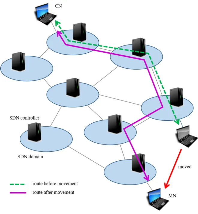
Figure 1.3: Network configuration example. controllers controlled by different administrators.
Figure 1.3 depicts a sample configuration of a multidomain SDN network we intend to work on. We consider a network within a range managed by each SDN controller an SDN domain and each SDN controller is assumed to be managed by different ad-ministrators. Thus, though each SDN domain is able to transfer flows to other SDN domains, the SDN controllers have no visual of other SDN domains.
1.2
Overview of the Study
1.2.1
Objective
The purpose of this research is to construct an inter-domain mobility management framework that continues communication even when a mobile node moves to another
SDN domain. To maintain communication quality, communications on the mobile nodes connected to a network are classified by their characteristics. Moreover, the communication path will be flexibly controlled based on the classification results. This provides users with a seamless and comfortable use of network services.
1.2.2
Challenges
(A) Challenges of the SDN based inter-domain mobility management.
To continue a comfortable communication even after a mobile node moves to another SDN domain, it is significant to share a necessary routing information on the mobile node and also set an inter-domain communication route. This is because it is necessary to set an appropriate communication route between the SDN domains so that the communication quality after movement does not deteriorate. Therefore, we set the following issues.
(A-1) Difficulty in sharing information among SDN domains efficiently.
To grasp the vision of an entire network composed of multiple SDN domains, it is significant to share information, such as mobile node information or information necessary for communication route selection within every SDN controller. This is because SDN controllers only manage the inside of an SDN domain, which they control. However, if all the SDN controllers in a network share an information, the amount of communication for network management increases. As a result, there is a communication delay, causing a likely increment in the network load. Furthermore, the network service quality may be degraded, or even the network service may stop, causing the network service usage to deteriorate.
(A-2) The difficulty of setting an efficient inter-domain communication route. When a mobile node moves to another SDN domain after transfer of the packet from the home SDN domain, the communication route becomes a redundant triangular routing, which may increase the communication delay. To prevent this, the communication route between a mobile node and its corresponding node has to be controlled after a movement of the mobile
node. However, similar to (A-1), it is difficult to manage an entire network composed of multiple SDN domains. Therefore, it is necessary to collaborate between administrative SDN domains and exchange the necessary informa-tion.
(B) Routing challenges after the movement of mobile nodes.
If we set a communication route, after a move of a mobile node to the mere shortest communication route, it may result in a significant reduction in commu-nication quality. It sometimes take time when switching a commucommu-nication route, ending up disconnecting the communication or dissatisfying the requirements needed for each communication. Therefore, we focus on improving communica-tion quality and set the following issues.
(B-1) The communication quality degradation caused by using only statical infor-mation.
To maintain the communication quality, it is necessary to set the commu-nication route properly after a move of a mobile node. In a real network environment, where only one communicating mobile node exists, many mo-bile nodes often communicate within the same network. Therefore, it is necessary to consider the communication status of other communicating mobile nodes.
(B-2) The difficulty in setting communication routes, satisfying the requirements of communication.
These requirements differ, depending on the type of network service that is communicating. For example, an available bandwidth would likely be plen-tiful for video streaming and low latency is preferred for network services, such as real-time translation services that frequently exchange small data. If a uniform routing standard is used for all the communication flows, it becomes difficult to respond to different requirements, and the quality of communication may be degraded.
Figure 1.4: The position of this study.
1.2.3
The Position of This Study
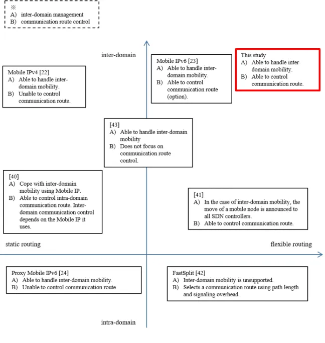
Figure 1.4 shows the brief summary of the position of this study.
Conventional SDN based mobility management approaches were proposed to man-age communication efficiently when a mobile node moves inside an SDN domain. This is because of the specialty of SDN; SDN can direct a network that is under the control of an SDN controller or a set of SDN controllers that centrally and flexibly collab-orate. However, as the IoT environment grew larger, the number of mobile devices that moved across the SDN domains increased. Therefore, it became difficult to cope
with the conventional SDN based mobility management approaches and it has also become necessary to take into account the inter-domain movement of mobile nodes. Hence, there is a need for studying SDN based mobility management that considers inter-domain movements.
I first adopted SDN to the multiple administrative domain network, which made the information exchange efficient. Owing to the characteristics of SDN, an SDN controller can only collect information from the SDN domain it manages. Hence, to perform inter-domain mobility management, an SDN controller needs information from other SDN domains. To attempt to obtain all the network management information from all the SDN domains in a network, we need an enormous amount of communication. In practice, only required information needs to be exchanged among the SDN domains related to mobility management. Hence, the SDN domains to exchange information can be limited to reduce the total traffic load. By achieving this reduction, we can avoid occupying the network resource with communications for mobility management. This is considered to contribute to maintaining a good network environment in the recent IoT environment, where traffic increases.
Also, when setting a communication route after a mobile node moves, it is necessary to select a suitable communication route flexibly to respond to various communication requirements. However, the existing SDN based inter-domain mobility management approaches have difficulty dealing with changing network state. The existing routing methods for SDN networks cannot qualify mobility management requirements while maintaining communication quality.
Therefore, we propose an end-to-end inter-domain routing method specific for mo-bility management. When selecting a communication route, the proposed method uses the characteristics of the communication and performs dynamic routing, based on them. Currently, there are various network services; however, they require different commu-nication needs, such as wide bandwidth and low latency. If uniform commucommu-nication route selection criteria are adopted in such a situation, it may be impossible to satisfy the requirements for the comfortable use of network services. Requirements can be roughly categorized and the difference is seen in the characteristics of communications. By classifying the flows based on the characteristics of communication and performing
routing according to the classification, it is possible to assign a communication route that provides network resources, satisfying the bandwidth requests and communication delay. This makes it possible to provide every mobile node with appropriate commu-nication conditions. In addition, there is no other attempt to apply routing methods using the characteristics of communication to mobility management.
In this study, we propose a new SDN based mobility management approach that ensures communication quality. Specifically, we focus on maintaining a high-quality communication after a mobile node moves across the SDN domains. First, we design an architecture for an SDN based inter-domain mobility management framework. Fur-thermore, we will extend the routing method after the movement of the mobile nodes and also aim for a flexible communication route selection. The effectiveness of the proposed framework and methods are verified through experiments.
The completion of this research will provide comfortable communication for mobile node users aware of mobility management. This will enable ordinary mobile node users to enjoy a comfortable communication environment without being conscious of any-thing. Currently, with the diversification of network services and increasing opportu-nities for mobile nodes to communicate, the realization of comfortable communication environments dramatically contributes to the society.
1.3
The Organization of This Thesis
Figure 1.5 shows the outline of this thesis.
In Chapter 1, the background of the study is described first, then the objectives, drawbacks, and the position of this study follow.
In Chapter 2, an SDN based inter-domain mobility management framework is pro-posed, which facilitates comfortable communication after a mobile node moves. This framework has two key functions: management information sharing function (MISF) and inter-domain routing function (IDRF). The efficiency of the framework is verified through simulation experiments.
in Chapter 3, an end-to-end routing mechanism aware of mobility management is proposed, which considers some information for routing. Also, simulation experiments
Figure 1.5: Outline of this thesis. are executed to verify the efficiency of the routing mechanism.
In Chapter 4, the routing mechanism proposed in Chapter 3 is extended to deal with the requirements of various communications flexibly. After automating the flow classification and communication route, setting procedures, the effectiveness of the expansion is assessed through simulation experiments.
Chapter 5 summarizes the research results and presents the conclusions of this study. Future issues are also listed.
Chapter 2
SDN Based Inter-domain Mobility
Management Framework
2.1
Introduction
2.1.1
Background and Overview
Owing to the widespread of the wireless network environment, it is now possible to use network services in various places and scenes. Network services, such as file transfer service, remote terminal service, and virtual desktop service are popularly used [1, 2]. Small-sized devices, such as laptop PCs, smartphones, and tablet PCs, capable of wireless communication, use the above mentioned network services. Throughout the rest of the study, we call any of these devices a mobile node (MN). Since MNs are portable devices, users tend to move around while using network services. With the particular case of session continuous network services, continuity of network services during movement becomes a critical problem. When an MN user moves and its device connects to an access point in a different network domain, the IP address of the MN changes. If a communication session is disconnected owing to the change in the IP address, problems such as lack of data and logout from network services emerge, which affect the use of network services. Thus, IP mobility management is essential for enabling the use of network services while moving.
Mobile IP is one of the IP mobility management, standardized by Internet Engi-neering Task Force (IETF) [22–24]. Mobile IP is a technology that enables continuous
communication when an MN user moves during a communication. If the MN user moves to a different domain, the technology still enables continuous communication, with the IP address used before the move. However, there are cases where the commu-nication route of an MN falls into triangular routing. This might lead to a degrade in the quality of service (QoS), caused by communication delay. Moreover, an MN must be equipped with a Mobile IP function and this is a challenge when applying all MNs. Some researches apply SDN to IP mobility management to solve the problems mentioned above [40, 41]. SDN is a technology that controls a network dynamically with a software [25]. By using SDN, an SDN controller centrally manages SDN switches in their domain and this enables nodes to communicate with a suitable communication route. However, existing researches focused mainly on the intra-domain move. To cope with the inter-domain move, with SDN, SDN controllers in different SDN domains have to exchange information about the movement of an MN. As a result, communication costs between SDN controllers may increase and might become a problem in practical use. Therefore, it is difficult to maintain an efficient communication when an MN makes an inter-domain move.
There are two major trends in which inter-domain handover with SDN can be han-dled. One approach is to use a Mobile IP when inter-domain handovers occur [41]. By using a Mobile IP, SDN controllers do not need to search for SDN domains to exchange information of MNs. However, Mobile IP has difficulty in communication route optimization. Another is to announce information of MNs to every SDN con-troller in the network [40]. This approach allows the communication routes to be optimized. However, with a network that comprises many SDN domains, communi-cation for the announcement might compress the communicommuni-cation bandwidth. These conventional approaches could only realize efficient data exchange or communication route optimization.
To overcome both problems simultaneously, we propose an SDN based IP mobil-ity management framework, focusing on the inter-domain handovers. Our proposed framework comprises two functions: MISF and IDRF. MISF effectively searches for a destination SDN domain of a moved MN and chooses minimum SDN controllers to share minimal information related to the communication of the MN to manage
infor-mation efficiently. IDRF calculates an appropriate communication route to allow the MN to continue effective communication.
We also conducted some experiments to confirm the effectiveness of our proposed framework. The results show that our proposal achieved to optimize the communication route and keep the traffic volume between SDN controllers low.
2.1.2
Novelty and Contribution
To realize efficient inter-domain handovers, we propose a novel framework to efficiently exchange the information of an MN between SDN controllers in each SDN domain and also optimize the communication route between an MN and a corresponding node (CN). Existing approaches do not realize these two requirements simultaneously be-cause these approaches differ in target, purpose, and assumed environment. Therefore, the existing approaches do not match the purpose of what we concentrate on this time. When Mobile IP emerged, communication route optimization had little meaning because there were not too many choices of a communication route, to be selected. Moreover, Mobile IP aimed at easy implementation without any modifications in net-work infrastructure, as it focused on practical use. Thus, Mobile IP does not have full support on communication route optimization. The SDN based methods do not aim at covering wide-area networks and they are approaches for deprived environments. Hence, they can handle inter-domain handovers; however, not efficiently. Our pro-posed framework realizes two things simultaneously: efficient information exchange between the SDN controllers and communication route optimization to achieve the inter-domain handovers in a large-scaled wide-area network, efficiently with functional support of network infrastructure.
With this novelty, mobile communication will be more seamless and delay-less. This leads to an improvement in communication quality for users moving around with their communicating MNs. For example, without our proposed mobility management framework, when users with mobile PCs move across SDN domains while downloading data from a cloud server, the disconnection of communication would occur and subse-quently lead to packet loss. Moreover, when the users move across SDN domains while using interactive-type applications, such as remote login terminal or remote virtual
desktop environment (VDI), a session would be interrupted. In addition, redundant communication route leads to severe communication delay, especially when users are handling large data. By using the proposed framework, MN users will be able to download or upload their data smoothly and perfectly, while moving around. As for the interactive-type applications, MN users will be able to use the network services without any termination of the process, even without the applications having the func-tion of switching connecfunc-tions when the IP address changes.
2.2
Related Works
2.2.1
Mobile IP
In this section, we introduce related works of IP mobility management and summarize their drawbacks. Internet Engineering Task Force (IETF) standardized Mobile IPv4 to realize IP mobility management [22]. Mobile IPv4 is a protocol that maintains communication between an MN and a CN, which communicates with an MN after the MN moves to other network domains. Figure 2.1 shows its overview. Mobile IPv4 uses a Home Address (HoA) and a Care-of Address (CoA) to continue communication after the move of an MN. HoA is an address an MN uses in the source domain and CoA is an address an MN uses in the destination domain. MN registers its binding-cache to its Home Agent (HA). Binding-cache is a set of HoA and CoA of an MN. The HA transfers the packets sent to HoA to CoA. However, depending on the location of the HA, an MN may communicate with a CN over a redundant communication route, which we refer to as a triangle routing problem.
IETF [23] also standardized Mobile IPv6. In addition to the functions of Mobile IPv4, it also has a communication route optimization function that enables MNs to communicate with the most suitable communication route. However, this is an optional function. Therefore, only the MNs that support communication route optimization can use this function. Moreover, the current IPv6 penetration rate is low, approximately 33% and accordingly, the penetration rate of Mobile IPv6 is low. Therefore, the prac-tical application of Mobile IPv6 is difficult.
Figure 2.1: Overview of Mobile IPv4.
as HoA, CoA, the lifetime of a Binding Cache, etc., among an MN, an HA, and a Foreign Agent (FA). IETF standardized Mobile IPv6 Management Information Base [45]. MIB defines a large amount of information needed for Mobile IPv6. To realize IP mobility management, it is essential to select a location to share plentiful information efficiently. In Mobile IPv4 and Mobile IPv6, the MN registers its binding cache to its HoA. Thus, there is no need to search for a location to share information.
In Mobile IPv4 and Mobile IPv6, the MN needs to conduct IP mobility manage-ment. However, Proxy Mobile IPv6 (PMIPv6) executes IP mobility management on network equipment [24]. Figure 2.2 shows its overview. The network equipment ex-ecutes the process for IP mobility management in PMIPv6. Therefore, there is no need for an MN to involve in IP mobility management. Local Mobility Anchor (LMA)
Figure 2.2: Overview of Proxy Mobile IPv6.
keeps bindings of HoA and Proxy-CoA. Mobile Access Gateway (MAG) detects MNs and registers bindings to LMA. After an MN moves, MAG registers the HoA and the Proxy-CoA binding of the MN to LMA. Packets sent to the HoA of an MN are trans-ferred to the MN via LMA. Like Mobile IPv4 and Mobile IPv6, PMIPv6 also has the triangular routing possibility.
2.2.2
SDN based IP mobility management
SDN enables us to control networks intensively and flexibly. Therefore, as a means to solve the communication route optimization problem, SDN has attracted attention. Using SDN, network devices execute all the IP mobility management processes. Thus, unlike Mobile IPv4 and Mobile IPv6, the MN does not need to be equipped with IP mo-bility management functions. For this reason, there are some IP momo-bility management
Table 2.1: Summary of related works. Approaches Mobile IPv4 [22] Mobile IPv6 [23] PMIPv6 [24] Paper [40] Paper [41] Intra-domain routing × △ △ ⃝ ⃝ Inter-domain routing × △ × ⃝ △ Domain selection to share information ⃝ ⃝ ⃝ × ⃝
approaches using SDN. Studies, [40] and [41], show communication route optimization mechanisms in the case when intra-domain handover occurs. However, in the case of an inter-domain handover, the mechanism in [40] uses a Mobile IP. Therefore, MNs need to be equipped with communication route optimization function to optimize commu-nication route after handover. The mechanism in [41] regards inter-domain handover as infrequent and broadcasts this event to all other SDN controllers. Therefore, the amount of traffic increases when inter-domain handover occurs frequently in a network that comprises many SDN domains.
2.2.3
Problems of related works
We summarized the drawbacks of the related works in Table 2.1. We confirm that existing works cannot realize an efficient selection of the SDN domain to share infor-mation, intra and inter-domain communication route optimizations, all together. The studies, [40] and [41], applied SDN to solve the Mobile IP problem, communication route optimization. However, SDN controllers can only control the SDN domain they manage. This means that these approaches focus on the intra-domain communication route. Nonetheless, in recent network environments, users move freely to various SDN domain networks while using network services. Therefore, we have to consider the IP mobility management in multiple SDN domain networks. To realize this, we need an SDN controller in each SDN domain to share information of MNs. However, if an SDN controller broadcasts the information to all other SDN controllers, it might cause large amount of traffic in a situation where inter-domain handover occurs frequently.
Hence, we need a mechanism to share information efficiently in multiple SDN domain networks.
2.3
SDN Based Inter-domain Mobility Management
Framework
2.3.1
Overview
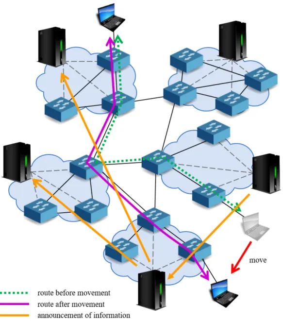
In this section, we propose an SDN based IP mobility management framework, con-sidering inter-domain handovers, to solve the problems explained in section 2.2. We first show the overview of our proposed framework and discuss the details of composed functions later. Figure 2.3 depicts the overview of our framework. This framework re-alizes inter-domain communication route control while sharing information efficiently with two functions: MISF and IDRF.
MISF searches for the source domain (the MN ’s SDN domain before movement) and decreases the number of SDN domains to exchange MN information, to reduce traffic load between SDN controllers. IDRF calculates an end-to-end communication route between an MN and a CN in the destination domain (the SDN domain the MN moved into) and announces this communication route only to the SDN domains in the selected route, to optimize inter-domain communication routes.
We assume that inter-domain topology changes do not occur frequently. Therefore, the SDN controllers have an inter-domain topology information. Inter-domain topology information consists of the following.
• IP address of an SDN controller in each SDN domain. • The network address of each SDN domain.
• The inter-domain link information.
The functions mentioned above use this inter-domain topology information to search SDN domains and also calculate communication routes.
We show the components of our proposal in Figure 2.4. The components include SDN controllers, SDN switches, an MN, and a CN. Our framework supports two layers
Figure 2.3: Overview of SDN based IP mobility management considering inter-domain handovers.
of a network: an SDN controller network and an SDN switch network. SDN con-troller network consists of SDN concon-trollers in each SDN domain. This network is used to exchange information to optimize the MN-CN communication route. SDN switch network consists of SDN switches.
Figure 2.4: Network configuration.
2.3.2
Management Information Sharing Function
We describe the detailed design of MISF with an example. The network used for the explanation is shown in Figure 2.3. We assume that an MN moves from a source to a destination domain during communication with a CN and an SDN controller of the destination domain, which detects the connection of an MN in the destination domain
(attachment of the MN). The IP address of the MN changes after this move. Below is the MAC address, the IP address that the MN used in the source domain (former IP address), and the IP address that the MN is currently using in the destination domain (current IP address).
• MAC address: 00:00:00:00:00:11 • former IP address: 10.0.1.1 • current IP address: 10.0.2.1
We define the names of the SDN domains and the SDN controllers that involve in the MN handover as below:
• SDN domains
– Dd: The SDN domain MN belongs to, after a move – Ds: The SDN domain MN belongs to, before a move – Dc: The SDN domain CN belongs to
• SDN controllers
– Cd: The SDN controller that manages Dd – Cs: The SDN controller that manages Ds – Cc: The SDN controller that manages Dc
Now we describe the MISF procedure, step by step. The Sequence diagram of MISF is depicted in Figure 2.5.
1. Cd searches for Ds, based on the MAC address of MN.
Cd sends queries in order, from neighboring SDN domains, as depicted in Figure
2.6. SDN controllers of the SDN domains that received the query search their SDN domain to check if the MN belonged to it, and send the result to Cd, for a
reply. When an MN was not in their SDN domain, they return the absence of the MN. However, when an MN was in their SDN domain, they return the IP address the MN used.
Figure 2.5: Sequence diagram of MISF
2. Cd generates node connection information from the IP address sent from Cs.
Node connection information consists of the following information.
• MAC address of an MN • former IP address • current IP address
In this example, the node connection information is as follows.
• MAC address: 00:00:00:00:00:11 • former IP address: 10.0.1.1 • current IP address: 10.0.2.1
Figure 2.6: Search for Ds.
Cd sends the information as shown in Figure 2.7. To send a node connection
information to a CN, Cd needs to know where the CN is, and the IP address
of Cc. Cd obtains the IP address of CN from the header of the packet sent
from the MN to the CN, and subsequently, derive the Cc information from the
Figure 2.7: Announcement of node connection information.
2.3.3
Inter-domain routing function
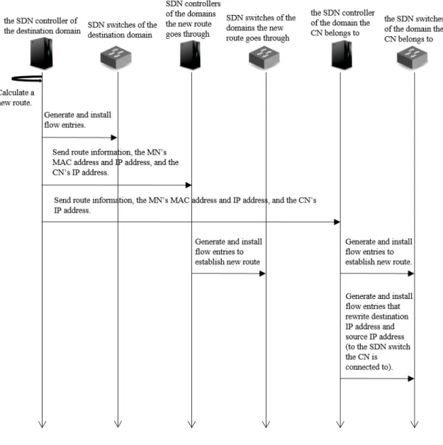
Next, we explain the detailed design of IDRF following the example we used in the explanation of MISF in section 2.3.2. The Sequence diagram of IDRF is depicted in Figure 2.8.
1. Cd calculates the MN-CN inter-domain communication route.
commu-Figure 2.8: Sequence diagram of IDRF
nication route. We consider the number of inter-domain hops (Nhop) and the
total number of flow entries that need installation in SDN switches (Nf low). This
is performed to select the shortest communication route that can suppress the resource consumption of the SDN controllers. Cd performs all the querying and
calculation in this procedure.
2. Cdannounces the communication route information to the SDN controllers of the
SDN domains that the selected route goes through.
In this example, Cdannounces a bundle of information needed for establishing the
such as the node connection information, the IP address of the CN, and the communication route information that indicates where the packets are to be transferred.
3. Each SDN controller generates flow entries based on the received communication route information and installs them to their corresponding SDN switches. In particular, it checks flow entries and rewrites the packets sent between the MN and the CN based on the node connection information at the SDN switch that the CN connects to. This keeps the MN IP address, seen from the CN, the same as before, while the actual IP address the MN is using is the current IP address. Hence it enables the communication to continue between the MN and the CN, just as before. Concretely, we set the flow entries, as shown below.
• Rewrite the destination IP address of the packets, sent from the CN to the
MN, from the former IP address to the current.
• Rewrite the source IP address of the packets, sent from the MN to the CN,
from the current IP address to the former.
We would explain the details of Step 1 above. We choose the communication route with minimum Nf low among the communication routes with minimum Nhop, in the
following steps.
1. Cd checks for communication routes with minimum Nhop based on inter-domain
topology information. We use a breadth-first search algorithm for this search. 2. If there is only one communication route with minimum Nhop, the framework
chooses it as the shortest communication route. If there are two or more commu-nication routes with a minimum Nhop, the Nf low of each communication route are
compared. Cd asks SDN controllers of each SDN domain to obtain the number
of flow entries needed for the installation of each communication route, as seen in Figure 2.10. The SDN controllers return the number of flow entries to Cd and
Cd calculates the Nf low of each communication route.
3. Cd chooses the communication route with minimum Nf low as the final decided
Figure 2.9: Announcement of inter-domain communication route.
2.4
Implementation
We indicate the implementation of the basic architecture of our framework, based on SDN networks. Figure 2.11 is its architecture. In this architecture, we introduce the two modules described above into the SDN controllers.
All the SDN controllers in a network have an inter-domain topology information. The inter-domain topology information consist of the network address of each SDN
Figure 2.10: Inquiring Nf low.
domain in the network, the IP address of the SDN controllers in each SDN domain, and the inter-domain link information. MISF and IDRF use this inter-domain topology information to search SDN domains and also calculate communication routes.
The MISF shares information on MNs and inter-domain topology information among the SDN controllers. The SDN controllers exchange this information for inter-domain handover processes. The IDRF exchanges communication route information and cal-culates a new communication route according to the proposed routing mechanism.
Figure 2.11: Basic architecture of our proposal.
For SDN controllers, we use OpenDaylight [46], and Open vSwitch [47] for the SDN switches. OpenFlow Protocol ver.1.3 [26] is used for communication between SDN controllers and their switches. We installed the two functions we introduced in section 2.3 into the SDN controllers. The IDRF obtains flow entry information from the SDN controllers via REST API.
2.5
Evaluation
2.5.1
Overview
We conducted experiments to validate the effectiveness of our proposed framework. We confirmed the reduction effect in the total communication amount, among the SDN controllers caused by MISF and the reduction effect on communication delay between an MN and a CN caused by IDRF.
We equipped two approaches for comparison with our proposed framework.
• Approach 1: announces the movement of an MN to all SDN domains.
We replaced MISF with a function that announces the move of an MN to all the SDN controllers, which behave similarly to those in [8].
• Approach 2: transfers packets sent to the MN from the source domain.
We replaced IDRF with a function that sets a communication route that transfers packets sent to the MN from the source domain. This approach sets a communi-cation route similar to that of the Mobile IPs [22–24, 40].
We constructed a virtual network as an experimental network with Mininet 2.2.1 [48]. The bandwidth capacities of the links between the SDN switches are all set to 1 Mbps and the delay of each link is set to 10 ms.
The experiments are conducted in the following manner:
1. An MN moves from Ds to Dd, five seconds after it starts a communication with
a CN.
2. Cdsearches for the source domain and retrieves the former IP address of the MN.
3. Cd generates the node connection information and announces it to Cc.
4. Cd calculates a new communication route between the MN and the CN.
5. Cd announces the new communication route to the SDN controllers of the SDN
domains involved in the route. Subsequently, the SDN controllers install flow entries in their SDN switches.
In this evaluation, we conducted three experiments.
• Experiment 1: Evaluation of MISF
• Experiment 2: Evaluation of IDRF
Figure 2.12: Experimental network topology (5 SDN domains).
2.5.2
Experiment 1: Evaluation of MISF
In Experiment 1, we focused on the total communication amount between the SDN controllers. We arranged three networks, consisting of 5, 10, and 15 SDN domains. The number of inter-domain hops between the source domain and the destination domain is 1. The SDN domains increase concentrically as shown in Figures 2.12, 2.13, and 2.14.
Figure 2.13: Experimental network topology (10 SDN domains).
Figure 2.15 shows how the total amount of communication changed as the number of SDN domains changed. In approach 1, the total communication amount increased as the number of SDN domains increased. In contrast, the total communication amount in the case of the proposed framework remained constant even though the number of SDN domains increased.
Figure 2.15: Experimental result 1: Traffic load of communication between SDN con-trollers.
Figure 2.16: Experimental network topology (1 hop between Dd and Ds).
2.5.3
Experiment 2: Evaluation of IDRF
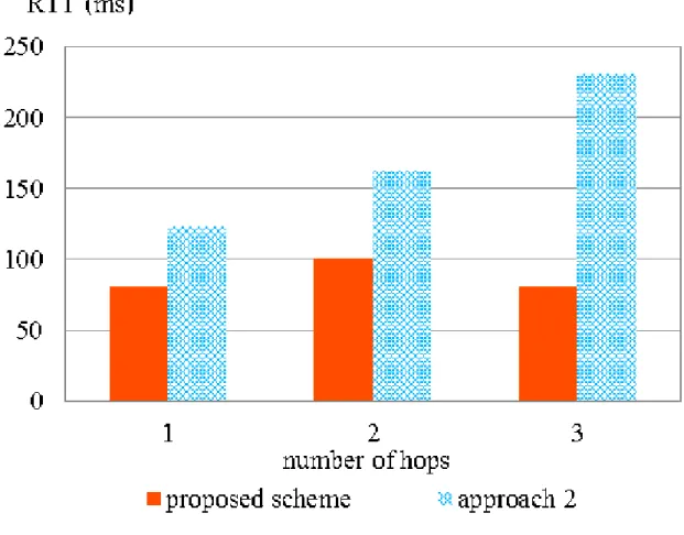
In Experiment 2, we focused on the communication delay (round trip time (RTT)) between an MN and a CN, communicating with a newly selected communication route after the move of the MN. We arrange a network with 10 SDN domains and set the number of inter-domain hops between Dd and Ds to 1 hop, 2 hops, and 3 hops, as
shown in Figures 2.16, 2.17, and 2.18.
Figure 2.19 shows the result of Experiment 2. In the case of approach 2, RTT increased according to the increase in the number of inter-domain hops between Dd
Figure 2.17: Experimental network topology (2 hops between Dd and Ds).
Figure 2.20: Experimental network topology (8 SDN domains).
2.5.4
Experiment 3: A comprehensive evaluation of the
pro-posed framework
In Experiment 3, we compared the total communication amount between the SDN controllers and the RTT between the MN and the CN of the proposed framework: approach 1, and approach 2. We set the parameters as below:
• The number of inter-domain hops between the MN and the CN: 1, 2, 3.
Figure 2.21: Experimental network topology (9 SDN domains).
Figures 2.20, 2.21 and 2.22 shows the topology of networks when the numbers of SDN domains are 8, 9, and 10, respectively. The MN moves as indicated by the arrows in the figures.
We show the total communication amount between the SDN controllers, for each number of hops between the MN and the CN, in Figure 2.23. The total communication
Figure 2.22: Experimental network topology (10 SDN domains).
amount increases as Dsgoes farther from Ddin the cases of the proposed framework and
the approach 2. Nonetheless, in the case of the approach 1, the total communication amount was not affected by the number of hops; however, it was influenced by the number of SDN domains.
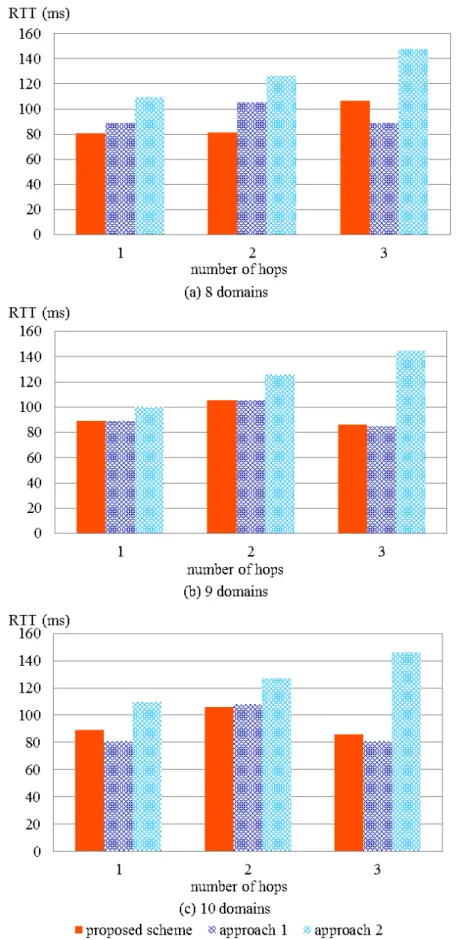
Figure 2.24 shows the RTT of the communication between the MN and the CN for each number of SDN domains. In the case of the proposed framework and approach 1, RTT differs by the number of hops; however, it is always smaller than that of approach 2 in any case. In the case of approach 2, RTT increased as the number of hops between
Dsand Ddincreased. Nevertheless, the results of the proposed framework and approach
1 showed no relevance to the number of hops between Ds and Dd.
2.5.5
Summary of evaluations
First, we discuss the results of Experiment 1. In the case of the proposed framework, the closer the source domain was to the destination domain, the smaller the traffic load because our framework queries from neighboring SDN domains.
However, the total communication amount of approach 1 increased as the number of SDN domains increased. This is because approach 1 announces the move of the MN to all the SDN domains in the network, regardless of the position of the source domain. Next, we discuss the results of Experiment 2. In the case of the proposed framework, the number of the inter-domain hops does not become greater than the number that can be taken by approach 2. Therefore, the communication delay in the proposed framework becomes smaller, compared with approach 2. This is because the longest communication route the proposed framework chooses is the same communication route chosen by approach 2.
Finally, we analyze the results of Experiment 3 according to the following view-points: the total communication amount among the SDN controllers and the RTT of communication between an MN and a CN after a move of the MN.
• The total communication amount among the SDN controllers.
The proposed framework had lower total communication amount than approach 1 in all cases. Approach 2 also had lower total communication amount than ap-proach 1 in the case where Ds and Dd were 1 and 2 hops away. However, as the
number of inter-domain hops between the source and the destination domains became bigger, the total communication amount of the proposed framework and approach 2 increased. When Ds and Dd were 3 hops away, the total
communica-tion amount of the proposed framework was pretty similar to that of approach 1 from Figure 2.23 (c). In view of the fact that Ds was 3 hops away from Dd, Cd
ended up searching all the SDN domains. Furthermore, when Ds and Dd were
all the approaches and the proposed framework marked a larger total communi-cation amount than that of cases with 1 and 3 hops. Approach 2 used MISF, the proposed framework function, for obtaining and announcing the move of the MN. Thus, the communication amount of this part was the same as that of the proposed framework. The difference came from the communication amount of IDRF. The difference in the way to select a new communication route caused the change in the amount of communication among the SDN controllers and this af-fected the total communication amount. Figure 2.23 (b) shows when Ds and Dd
were 2 hops away, the total communication amount of the proposed framework and approach 1 greatly exceeded that of approach 2. In this case, there were sev-eral communication routes with minimum inter-domain hops. Therefore, IDRF queried other SDN controllers for the number of flow entries that was needed to be installed for each communication route. This querying caused the increase in the communication amount. This fact shows that by querying the number of needed flow entries, the total communication amount among the SDN controllers increases.
• The RTT of communication between the MN and the CN after the move of the
MN.
The results show that in the case of approach 2, the RTT increased as the number of hops between Ds and Dd increased. In approach 2, packets sent to the MN
are first sent to Ds. Thus, the communication route becomes longer as the MN
moves farther. In contrast, the proposed framework and approach 1 selected the shortest communication route regardless of the position of Ds. Therefore, the
RTT did not get too large. Besides, the transferring communication route that approach 2 selected is the longest communication route that could be chosen in the proposed framework and approach 2. Thus, these approaches could maintain RTT like approach 2 or make it smaller.
From the results mentioned above, we can say that approaches 1 and 2 can only hold back either the RTT of communication between an MN and a CN after the move of the MN or the total communication amount among the SDN controllers. In contrast,
the proposed framework is able to deal with both.
2.5.6
Discussion
These quantitative experimental results mentioned above reveal the contribution of our proposed framework in practical use. This achievement enables the suppression of the consumption of limited network resources while enabling users of MNs to move around, maintaining seamless and fast communication even if they moved across SDN domains. For example, consider the situation where many users work with a laptop PC or a tablet PC to download data from cloud servers or to upload data. The users can smoothly download/upload large data from/to cloud servers while they are moving (e.g. during transit time). Concerning interactive-type applications, such as remote login terminal or VDI environment, the users can use the network services continuously when the connecting SDN domain changes.
Generally speaking, to avoid the termination of network services or processes when MNs move across SDN domains, application-level handover function is usually imple-mented in the applications. When the IP address of an MN changes according to the move of the MN, the handover function terminates the transport connection on the previous IP address and then establishes a new transport connection on the new IP address. By this function, the data communication sessions seem to continue transpar-ently and also application logic can handle the sessions seamlessly. However, not all applications have this feature implemented. This is because the mechanism is relatively complicated and it is necessary to deal with the server-side as well. Our framework enables this functionality at the network level. It means that all the Internet applica-tions can utilize their network-dependent funcapplica-tions seamlessly, in situaapplica-tions where the MNs move across SDN domains.
Furthermore, when a user is at a place where the service areas of different access points overlap, the MN shifts its connecting access point back and forth, depending on the link condition even when the user is stationary. The proposed framework currently does not cover this kind of handovers; however, it has the potential to manage the handovers and keep communication quality high. Meanwhile, a standardization activity of a fast-initial setup of Wi-Fi links is progressing like IEEE802.11ai [15]. This function
would enable a Wi-Fi client to establish a secure link setup within 100 ms. If this standard will widely be used in the above environment, switching of access points may occur very rapidly and frequently in the near future. There are no modern technologies available to deal with such situations and we anticipate our proposed framework will work effectively in such situations.
2.6
Conclusion
This chapter aimed at realizing seamless connections and selecting suitable communi-cation routes in SDN based IP mobility management on inter-domain handovers. It is difficult to realize efficient information exchange between the SDN controllers and communication route optimization together. To solve this problem, we proposed the SDN based mobility management framework, considering inter-domain handovers. As the evaluation results show, we were able to optimize the communication route while retaining the total amount of communication among SDN controllers that was needed to manage low mobility management.
IDRF needs improvement in future works. By extending the algorithm to introduce metrics of paths, we can take more kinds of information into account, such as the bandwidth of inter-domain links and network usage.
Chapter 3
Communication Quality Aware
Routing Mechanism for Mobility
Management
3.1
Introduction
In Chapter 2, we tackled the challenges that hindered the application of SDN to inter-domain mobility management. We proposed an SDN based inter-domain mobility management framework as the first step to provide MN users, seamless and comfortable communication while moving around. The proposed framework selects the shortest communication route as the new route applied to the communication after the move of an MN.
Thanks to the growth of network services, there are many kinds of network services today, such as video streaming services, chat services, online games, and etcetera. They have different requirements for communication, depending on what they do and how they communicate. Hence, selecting a proper communication route will ensure or even increase the comfortability of communications.
Many researchers have proposed the SDN based mobility management approaches that handle inter-domain handovers [40, 42, 43]. However, they do not control the com-munication route after an inter-domain handover or the information used for selecting a communication route is insufficient. Routing approaches to optimize inter-domain
communication routes in an SDN environment are also proposed [49–52]. Though they are capable of inter-domain routing, they are not designed for mobility management and do not nicely fit with mobility management.
As a result, we propose an SDN based end-to-end routing mechanism, specified for mobility management. The inter-domain routing function selects a suitable end-to-end communication route for communication between an MN and a CN after the MN has moved across the SDN domains, based on parameters selected for mobility management. We have designed a basic inter-domain routing mechanism and showed its effectiveness. However, this mechanism mainly considers only the number of SDN domains a new route goes through. Lack of information for selecting a new route causes problems in the QoS after switching the route; moreover, this affects the time it takes to switch an old communication route to a new one. Therefore, we extend our routing mechanism by introducing new parameters, such as the number of inter-domain hops, real-time bandwidth availability of the links between the SDN domains, and the number of flow entry operations.
In this chapter, we extend the IDRF of the SDN based inter-domain mobility man-agement framework and confirm the efficiency of our new routing mechanism, through evaluations. The evaluation results show that our routing mechanism can reduce com-munication delay and data transfer time. Therefore, it realizes the comfortable use of network services. The contribution of this study is to show the evaluation and effectiveness of our new routing mechanism.
3.2
Related Works
3.2.1
SDN based mobility management
We introduce some approaches that apply SDN to mobility management. M. Idri uses the routing header to keep communication without using IP tunneling mechanism [43]. However, his work does not focus on communication route selection. Thus, we might end up with a lengthy communication route and we also need a master SDN controller to manage the SDN controllers, leading to an additional cost. P. Shrivastava et al. presents FastSplit that reuses the previous communication route to reduce signaling
overhead while it retains the new route near optimal [42]. FastSplit method uses the length of paths and signaling overhead to select a new route; however, it does not take real-time information into account. Y. Wang et al. proposed a Mobile IP based mobility management that copes with inter-domain handovers [40]. This approach uses Mobile IP for inter-domain handovers. Thus, MNs need Mobile IPv6’s route optimization function to realize route optimization. However, not all MNs support Mobile IPv6 or its route optimization function.
In Chapter 2, we proposed an SDN based mobility management framework that focuses on inter-domain handovers. Its overview is shown in Figure 3.1. Each SDN controller manages its own SDN domain and communicates with other SDN controllers to exchange necessary information. Although we succeeded in reducing communication delay, we had a few problems in the routing mechanism. This is because we did not consider route switching costs, such as the time needed to calculate a route and its flow entry installation time. To avoid disconnection, communication routes are updated before a TCP session disconnects. Therefore, we need to consider the calculating time of the communication route and the time an SDN controller needs to add, change, or delete flow entries to SDN switches, which we refer to as flow operation, real-time network usage, and processing time. Not considering these features might result in a low throughput communication route or session disconnection, which lead to serious QoE degradation. Moreover, the framework we proposed in Chapter 2 targets a situation with only one communication in a network. Especially, our previous algorithm does not consider the bandwidth availability affected by other communications. In usual networks, many MNs communicate with their CNs. Thus, we have to take other communications into consideration to avoid using low bandwidth links.
3.2.2
Routing approach in SDN networks
There are several inter-domain routing mechanisms that use SDN. In [49], the authors show a routing mechanism based on path cost and the number of flow operations. However, this mechanism focuses on link failure owing to disasters or accidents. Thus, it is not suitable for mobility management because it does not consider the move of an MN.
Figure 3.1: Overview of the SDN based mobility management proposed in Chapter 2.
In [50], the authors show a network model for an end-to-end QoS provisioning in inter-domain cases. This model selects a route, mainly focusing on bandwidth. Thus, there are problems with communication delay and the time taken for changing the communication route for mobility management.
K.Phemius et al. [51] propose architecture for the distributed SDN controllers. Since the routing in this approach is not made for a specific use, it is hard to apply it to mobility management.
N. Figueira et al. [52] indicate a hierarchical multi-domain SDN Controllers ’frame-work. It requires a master SDN controller to manage other SDN controllers. Thus, this leads to an additional cost.
3.3
Communication Quality Aware Routing
Mech-anism for Mobility Management
3.3.1
Overview and Design
To solve the problems we mentioned above, we propose a mobility management spe-cific end-to-end routing mechanism. Our basic concept of routing mechanism is to consider a balance between the quality of communications and the operation costs. For example, if we select a communication route with the fewest inter-domain hops, it may reduce the communication delay. However, there is a risk of selecting a very low throughput communication route. On the other hand, if we focus on high throughput, communication delay might become large. Requirements vary depending on the kind of network service an MN user is using. If the user is using a network service like video streaming, it requires high bandwidth. Also, if the user is using a network service like chat application that requires high performance and real-time communication, it ought to require a low communication delay. Moreover, most importantly, we have to avoid session disconnection. Thus, the entire processing time for a handover cannot exceed the total time-out limit. According to the mentioned concepts, we defined the parameters for the calculation of communication routes.
• The number of SDN domains each route candidate goes through (the number of
hops)
• The number of flow operations for each route candidate
• Real-time bandwidth usage information
The values of each information are normalized and added individual importance to the values to be used for calculating routes.
We use the SDN based inter-domain mobility management framework proposed in Chapter 2 as the base and change the routing mechanism used in IDRF to the one proposed in this chapter. The components and the architecture of the framework are the same as in Chapter 2, depicted in Figure 2.4 and Figure 2.11. Each SDN controller manages its own domain and they also hold inter-domain topology information. SDN controllers communicate with one another in the controller network and also the SDN switches are connected with one another via the data network.
The process of the proposed end-to-end mechanism is explained in Figure 3.2. The SDN controller of the destination domain calculates the switching route and subse-quently, other SDN controllers send the required information to it.
Mk = MFk + MDk + MBk (k = 1, 2, . . . , K) (3.1)
Equation (3.1) is used for calculating the total metric of each listed route. Mk
stands for the total metric of route k. MFk stands for the metric for flow operations,
MDk stands for the metric for the number of inter-domain hops, and MBk stands for
the metric for the bandwidth availability of the communication route.
MDk = Dk Dmax α (3.2) MFk = Fk Fmax β (3.3) MBk = (1− Bk Bmax )γ (3.4) Equation (3.2) defines the calculation of the metric, for the number of inter-domain hops, Equation (3.3) defines the calculation of the metric, for the flow operations and equation (3.4) defines the calculation of the metric, for the available bandwidth of each route. Dk indicates the number of SDN domains route k goes through, Fk indicates
the number of flow operations to the switch communication route, k, and Bk shows the
minimum bandwidth of route k. Dmax indicates the number of SDN domains in the
network and Bmax is the largest bandwidth in the network. Fmax becomes 2N when
we set the number of SDN domains in a network as N . This is because we need to set the flow entries for both ways of communication between an MN and a CN. α, β, and γ are the importance of each piece of information that is added to achieve balance
Figure 3.2: Flowchart of route calculating process.
among parameters. The values of importance can be set differently for each network to enable a network administrator to set its own importance according to the conditions of the network.
Our routing mechanism calculates Mkfor every possible communication route
with-out loops and selects rwith-oute k when Mkis minimum. Based on this process, our routing
mechanism can select an effective route for mobility management, to keep seamless and comfortable communication.
3.3.2
Example of a Routing Process
We would show an example of a routing process following the flowchart (3.2). Figure 3.3 indicates the network used to explain the routing process. The numbers near the links are their bandwidths. When an MN, communicating with a CN, moves to another SDN domain, the SDN controller of the destination domain detects the movement. Afterwards, the SDN controller creates a list of all possible routes from the MN to the CN. Figure 3.4 shows part of the route list. There are many possible routes from the MN to the CN; however, for convenience, we list up just three routes: route 1 (r1) to route 3 (r3). The proposed routing mechanism calculates the metric, Mk, for each
route. In this case, Fmax is 16; Dmax is 8; and Bmax is 5. We set the importance, α, β,
and γ, to 1 for a simple calculation.
M1 = MF1 + MD1 + MB1 = 6 16 + 5 8 + (1− 1 5) = 1.80 (3.5) M2 = MF2 + MD2 + MB2 = 8 16 + 5 8 + (1− 4 5) = 1.33 (3.6) M3 = MF3 + MD3 + MB3 = 10 16 + 5 8 + (1− 4 5) = 1.45 (3.7) In this example, M2 is the minimum metric; thus, the routing mechanism selects
route 2. As mentioned in the example, our routing mechanism can select an effective route, balanced among the number of SDN domains, to go through the number of flow operations and available bandwidth.


![Table 2.1: Summary of related works. Approaches Mobile IPv4 [22] Mobile IPv6 [23] PMIPv6[24] Paper[40] Paper[41] Intra-domain routing × △ △ ⃝ ⃝ Inter-domain routing × △ × ⃝ △ Domain selection to share information ⃝ ⃝ ⃝ × ⃝](https://thumb-ap.123doks.com/thumbv2/123deta/5907713.1049976/26.892.151.813.156.375/summary-related-approaches-mobile-mobile-routing-selection-information.webp)