Fabrication of continuous mesoporous carbon films with face‑centered orthorhombic symmetry through a soft templating pathway
著者 Tanaka Shunsuke, Katayama Yugo, Michael P.
Tate, Hugh W. Hillhouse, Miyake Yoshikazu journal or
publication title
Journal of Materials Chemistry
volume 17
page range 3639‑3645
year 2007‑06‑08
URL http://hdl.handle.net/10112/5587
Fabrication of continuous mesoporous carbon films with face-centered orthorhombic symmetry through a soft templating pathway
Shunsuke Tanaka,*ab Yugo Katayama,a Michael P. Tate,c Hugh W. Hillhousec and Yoshikazu Miyakeab
Received 16th April 2007, Accepted 8th June 2007
First published as an Advance Article on the web 28th June 2007 DOI: 10.1039/b705692c
Preparation of well-ordered continuous mesoporous carbon films without the use of an intermediate inorganic template was achieved by spin coating of a thermosetting phenolic resin, resorcinol/phloroglucinol/formaldehyde, and a thermally-decomposable organic template, Pluronic F127 (PEO106–PPO70–PEO106). The carbon films were deposited onto silicon, platinum/
silicon, copper, glass, and quartz substrates. Afterwards, decomposition of the organic template and solidification of the carbon precursors are simultaneously performed through a carbonization process. The resulting films referred to as CKU-F69, are (010)-oriented, and possess a face- centered orthorhombicFmmmsymmetry. Film periodicity is maintained even after a 68% uniaxial contraction perpendicular to the substrate brought on by carbonization at 800uC. This method could facilitate the mass-production and creation of new carbon and carbon–polymer porous films that find broad potential applications in catalysis, separation, hydrogen storage, bioengineering, nanodevices, and nanotemplates.
Introduction
Recent attention has been attracted to porous carbonaceous materials due to their high surface area, large pore volume, and chemical inertness. Traditional synthesis methods, which involve carbonization of activated carbon,1–3 produce only disordered materials. To date, synthesis of highly ordered porous carbon films remains challenging. Research efforts to produce porous carbon materials with well-tailored pore systems have focused on the use of various inorganic template materials such as porous anodic aluminum oxide (AAO) films, zeolites, siliceous opals, and mesoporous silicas to template the carbon.
The use of AAO films, which have uniform straight channels with 10–250 nm diameters, as templates for the synthesis of carbon deposits on the channel walls has been successful.4–6 The resulting tubular carbon materials have tunable diameters, lengths, and wall thickness. Additionally, the uniformity of the carbon nanostructures had never been seen before in carbon nanotubes when compared with carbon nanostructures pre- pared by conventional arc-evaporation or catalytic chemical vapor deposition (CVD) techniques.6 However, the carbon nanostructures are not interconnected and more or less collapse upon template removal.
During the past decade, synthesis of free-standing ordered microporous carbon materials has focused on the use of zeolite templates. The resulting materials have ordered and uniform angstrom-sized pores.7,8However, long-range ordered
microporous carbon replicas require repetitive carbonization steps to completely fill the template pores.8
Silica opals, also called colloidal crystals, which are made by the self-assembly of uniform submicrometre-sized silica spheres, have been used as templates for the synthesis of ordered macroporous carbons.9,10 The porosity and contact sites between the silica spheres provided walls and intercon- nected spherical pores, respectively, in the resulting carbons.
Similarly, synthesis of ordered mesoporous carbons has focused on the use of ordered mesoporous silicas with inter- connected pore structures as templates.11–19Ordered structures of mesoporous silicas are derived from the self-assembly of organic structure-directing agents and silica precursors.20–22 The development of the M41S20family triggered the synthesis of a wide variety of mesoporous materials with diverse sym- metries using various structure-directing agents such as the quaternary ammonium cationic surfactants, nonionic oligo- meric surfactants, and nonionic triblock copolymers.20–22As a result, various mesoporous carbon nanostructures with different pore systems have been synthesized using a variety of different mesoporous silica templates.13,15,16,19
The pore system of mesoporous carbons is inversely replicated from the silica templates, and the carbons usually preserve the bulk powder morphology of the silica. Thus, to control the mesostructural property and morphology, it is necessary to prepare the silica with different pore systems and morphology.
Pore size is controllable by selecting silica templates of different lengths and adjusting the silica wall thickness,14 though there is no report of tailoring only the silica wall thickness of the mesoporous silicas with constant pore diameter. Additionally, pore size can also be controlled by changing the pore diameter of the silica templates and adjusting the ratio of carbon source to silica.19 From the standpoint of morphology control, the use of mesoporous silica thin films, rather than bulk powders, are unsuitable as a
aDepartment of Chemical Engineering, Faculty of Engineering, Kansai University, 3-3-35 Yamate-cho, Suita-shi, Osaka 564-8680, Japan.
E-mail: [email protected]; Fax: +81-6-6388-8869;
Tel: +81-6-6368-0851
bHigh Technology Research Center, Kansai University, 3-3-35 Yamate- cho, Suita-shi, Osaka 564-8680, Japan
cSchool of Chemical Engineering, Purdue University, 480 Stadium Mall Drive, West Lafayette, Indiana 47907, U. S. A.
PAPER www.rsc.org/materials | Journal of Materials Chemistry
Downloaded on 08 November 2011 Published on 28 June 2007 on http://pubs.rsc.org | doi:10.1039/B705692C
template because of the lack of pore accessibility in the silica films. Then, it is difficult to maintain the continuous film and film adhesion to the substrate may become poor. On the other hand, mesoporous carbon films have been prepared by spin coating of sucrose/silicate nanocomposite and subsequent removal of the silica.23 However, the films obtained in this method show disordered pore systems.
All the above techniques require preparation of inorganic templates, impregnation of template pores with appropriate carbon precursors, carbonization, and subsequent selective removal of the templates using hydrofluoric acid or sodium hydroxide. Typical processes to introduce the carbon pre- cursors are infiltration of sucrose or phenolic resin, vapor phase infiltration, CVD, and plasma-enhanced CVD. Often, these time-consuming and costly steps require multiple infiltrations to complete the filling of the template pores.
Alternative methods, which eliminate the need for an inorganic template, have recently been developed to synthesize highly ordered mesoporous carbons,24–29by directly assembly of organic templates with the carbon precursors. Bulk mesoporous carbons with several unique structures have been synthesized, including a two-dimensional hexagonal phase p6mm,24,25,27,28a body-centered cubic phaseIm3m,25,27,28and a gyroid-based cubic phaseIa3d26–28. Besides the variation of structure, the morphological control of self-assembled organic precursor/organic template structures has been a key break- through towards the development of practical applications.
We noted that the organic templating approach seems to be advantageous for control, particularly in film morphology.
Development of well-ordered mesoporous carbon films will lead to new applications such as separation membranes and electronic devices. However, to date ‘‘ordered’’ mesoporous carbons in film morphology have not been fully synthesized and characterized in detail. Further understanding is required toward fabrication of continuous ordered meso- porous carbon films.
Here, we report a simple and reproducible synthesis of highly ordered mesoporous carbon films using an organic–
organic interaction approach. Two different kinds of phenolic resin monomers, resorcinol and phloroglucinol, with formal- dehyde and PEO106–PPO70–PEO106 (Pluronic F127) triblock copolymer were chosen as the thermosetting polymer and the thermally-decomposable template, respectively. Completely continuous films made of ordered mesoporous carbon are obtained by adjusting the molar ratios of resorcinol and phloroglucinol to each other and to the triblock copolymer.
The mesophase topology, order, and orientation of the films were characterized by the combination of grazing-incidence small angle X-ray scattering (GISAXS), field emission scan- ning electron microscope (FESEM), and transmission electron microscope (TEM) measurements.
Experimental
Chemicals
Resorcinol (abbreviated as Res; Scheme 1a), phloroglucinol (abbreviated as Phl; Scheme 1b), formaldehyde (36–38 wt%), 5 N HCl, and ethanol were purchased from Wako Pure Chemical Industries and used as recieved. Pluronic F127
(abbreviated as F127) was purchased from Sigma-Aldrich Chemical Co. and used as received.
Synthesis
Res and Phl were completely dissolved in an ethanol–water (20 : 80,y39 wt% ethanol) solution, and then HCl was added and stirred for 30 min. F127 was added into the above precursor solution. After complete dissolution of F127, formaldehyde was added to the above solution. A homo- geneous solution with the molar ratios 0–8 Res : 0–8 Phl : 0.01–0.1 F127 : 18 formaldehyde : 0.2 HCl : 20 ethanol : 80 water was applied onto substrates and then the substrate was spun up to 2000 rpm for 1 min using a SPINCOATER 1H-D7 (Mikasa Co.). Substrates of silicon, platinum/silicon, copper, glass, and quartz were used in this study. For polymerization of the Res and Phl with formaldehyde, the as-deposited samples were preheated at 100uC for 1 h, in air.
Then, the resultant brown deposit was carbonized under a nitrogen atmosphere from 200 to 800uC for 3 h at a heating rate of 1uC min21.
Characterization
The ordered structure of the samples was investigated with a JEOL JDX-3530S diffractometer using Cu-Karadiation with l= 1.5418 A˚ in Bragg–Brentano scan mode. The copper anode was operated at a voltage of 40 kV and a current of 20 mA.
Beam aperture was manually adjusted using a divergence slit for the beam source and scattering slit for the detector to reduce background scattering and limit the beam divergence.
Diffraction patterns were collected over the range of 0.8–4u2h at a scan rate of 1.2u2hmin21and a step size of 0.01u. Two- dimensional GISAXS was used to determine the symmetry, order, and orientation of the films. 2D GISAXS measurements were performed using a three-pinhole SAXS camera with a microfocus X-ray source, an Osmic MaxFlux confocal X-ray optic, and a gas-filled 2D multiwire detector at a camera length of 1424 mm. Due to the presence of an intense specular beam at grazing angles of incidence, aluminum strips were used to attenuate the scattering along the specular plane. All GISAXS patterns were collected at an angle of incidence of 0.2u, just above the critical angle. A schematic of the geometry of the GISAXS setup is shown in Fig. 1. The GISAXS patterns were analyzed using a Mathematica-based program called NANOCELL.30 The nitrogen adsorption/desorption iso- therms of the carbon films peeled from the substrate were measured at2196uC using a BELSORP 28 instrument (Bel Japan) and the surface area found using the Brunauer–
Emmett–Teller formalism. The pore size distributions were calculated by the Dollimore–Heal method using adsorption Scheme 1 The two different kinds of phenolic resin monomer in this study.
Downloaded on 08 November 2011 Published on 28 June 2007 on http://pubs.rsc.org | doi:10.1039/B705692C
View Online
and desorption branches for the mesopore analysis. TEM images of the mesoporous carbon films were recorded on a JEOL JEM-2010 microscope at an acceleration voltage of 200 kV. FESEM images were recorded on a JEOL JSM-6700 microscope at an acceleration voltage of 15 kV. The samples were not coated before the FESEM measurements. Raman spectra were recorded with a JASCO NRS-3100 spectrometer using a 532 nm laser as an excitation source. A carbonization experiment under a nitrogen atmosphere was performed by thermogravimetric analysis with a Shimadzu DTG-50.
Samples were heated to 900 uC at a heating rate of 10uC min21under nitrogen flow (100 ml min21).
Results and discussion
The XRD patterns of initial efforts to synthesize highly ordered continuous carbon films using only Res or Phl are shown in Fig. 2a. The molar ratio of carbon source to F127 was 200. Note, similar results were shown for molar ratios ranging from 80 to 800. With Res monomer the only carbon source in the spin coating solution, a Bragg diffraction peak
was observed at around 1.3u2h. However, the resulting films were not homogeneous. In contrast, when only Phl was used, continuous films were synthesized, but without an ordered structure as determined by the lack of Bragg diffraction peak in the XRD pattern. From these observations, it was hypothesized that by combining Res and Phl at various molar ratios, ordered continuous carbon films could be synthesized.
At Res/Phl molar ratios of 0.5 and 1, no periodic structure was confirmed from the XRD patterns of the continuous carbon films prepared, but at a molar ratio of 3, continuous films with mesostructural regularity were synthesized. On the basis of this data, subsequent carbon films were prepared with a Res/Phl molar ratio of 3.
Next, the molar ratio of phenolic resin monomers to F127 (RP/F127) was adjusted from 80 to 800. Fig. 2b shows the XRD patterns of these continuous carbon films carbonized at 400 uC. In all runs, the concentrations of the phenolic resin monomers were held constant. Thus, the RP/F127 molar ratio was changed by varying the concentration of the F127.
When the molar ratio of RP/F127 ranged from 160 to 230, the observed reflection peaks produced d-spacing values of 5.6–6.6 nm. Additionally, the formation of the ordered structure did not depend on the kind of substrate used in this study. Fig. 2c shows the variation of the d-spacing values of the first observed peak as a function of the RP/F127 molar ratio. It is conjectured that the change in thed-spacing values is derived from a difference in mesophase topology and orientation, or may be attributed to changes in porosity due to changes in the pore size and/or pore wall thickness. The detailed study will be reported in due course.
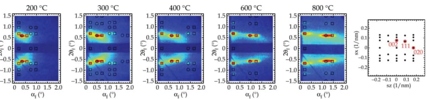
When ordered mesoporous materials are synthesized in film morphology, the mesostructure tends to orient with a specific (hkl) plane parallel to the substrate. As such, film lattice constants are notoriously difficult to identify from XRD patterns alone, because of the limited number of observed peaks. Additionally, it was demonstrated that refraction effects of XRD are not negligible for many of the mesostructured films.31To remedy this, we have used GISAXS to determine the topology, order, and orientation of the films. GISAXS patterns were collected from films prepared at Res/Phl and RP/F127 molar ratios of 3 and 200, respectively, and then carbonized at temperatures from 200 to 800uC (Fig. 3). The films prepared under these synthetic conditions are referred to as CKU-F69. Interpretation of the GISAXS patterns was aided by NANOCELL,30a program which simulates quanti- tatively the positions of Bragg diffraction peaks based on the distorted-wave Born approximation (DWBA) to account for the effects of refraction and reflection at the film–substrate and film–air interfaces. The experimental results were fitted to a face-centered orthorhombic Fmmm structure with the (010) planes parallel to the substrate, but where other planes were free to rotate about the substrate normal. The lattice constants for CKU-F69 carbonized at 200 uC were determined to be a= 18.2 nm,b= 21.0 nm, andc= 25.8 nm. The mesophase with cell parameters and orientation with respect to the substrate is shown schematically in Fig. 4. Note that the F127 has a very broad region in its binary temperature–concentra- tion phase diagram over which a body-centered cubic phase is obtained.32Upon the initial assembly, it is conjectured that the Fig. 1 Setup used for GISAXS data collection.
Fig. 2 (a) XRD patterns of the carbonized carbon products prepared at different resorcinol/phloroglucinol (Res/Phl) molar ratios. (b) XRD patterns of continuous carbon films prepared at different molar ratios of phenolic resin monomers and Pluronic F127 (RP/F127).
Preparation of the carbon films was carried out at the Res/Phl molar ratio of 3. Products were calcined at 400uC with nitrogen flow. (c) The variation in thed values of the carbon films as a function of the RP/F127 molar ratio.
Downloaded on 08 November 2011 Published on 28 June 2007 on http://pubs.rsc.org | doi:10.1039/B705692C
mesostructure is described by the body-centered lattice, likely a (110) oriented Im3m cubic close packing of micellar aggregates. The Fmmm mesostructure results from uniaxial shrinkage of Im3m symmetry along the substrate normal.33 Mesoporous films made of silica and tin oxide, which possess identical space groups and orientation, prepared using same copolymer, have also been reported in the literature.33–35 In addition to the Bragg diffraction peaks in the GISAXS patterns, there is a diffuse ring present in the pattern. A diffraction ring superimposed on the octagon-shaped spot pattern indicates the presence of some polyoriented domains in the film. In other words some domains are not perfectly aligned about the substrate normal. Furthermore, the critical angle for X-ray scattering from the mesoporous carbon film was measured by GISAXS. The critical angle decreased from 0.16u to 0.15u after carbonization at 400 uC, indicating the reduction of the average electron density of the film due to removal of the template. In addition, at carbonization above 600uC further reduction of the critical angle to 0.14uindicates a decrease in the density of the carbonaceous framework.
The color of the film was brown after carbonization at 200uC (Fig. 5a). The films turned black after carbonization at
400uC (Fig. 5b). As can be seen from the photograph images in Figs. 5c–e, the carbon films, which have film area of about 10 cm2, were completely continuous and tightly adhered to the substrate even after carbonization at 800 uC. The ordered mesostructures were also preserved during this high tempera- ture carbonization process. However, the interplanar distance, d010, did decrease, and at the same time there was a decrease in the film thickness as measured by using FESEM that followed a similar trend (Fig. 6). The shrinkage percentage of the film carbonized at 800uC was calculated to be 68%. The majority of the decrease in the d010 value was observed at a carbonization temperature of 400 uC, which corresponds to 66% of total contraction. This result implies that the majority of the residual hydroxyl groups in the carbonaceous walls condense at elevated temperatures. This temperature also corresponds to the decomposition of the majority of the organic template, as described in detail below using nitrogen sorption and thermogravimetric analyses (Fig. 7). In contrast to the changes observed in the blattice constant, the other parameters,aandc, did not change during the carbonization process, indicating that the shrinkage in the directions parallel to the substrate was hindered by the adhesion of the coating.
Fig. 8a shows the FESEM image of the cross section of CKU-F69 carbonized at 600 uC. A continuous and flat film about 700 nm thick was grown from the substrate. A periodic Fig. 3 GISAXS patterns of CKU-F69 calcined in a nitrogen atmosphere at 200–800uC. The overlay of simulated spots is from a NANOCELL simulation. The circles and squares identify transmitted and reflected Bragg peaks, respectively. In addition, NANOCELL simulated reciprocal space of an (010) orientedFmmmwith many domain orientations about the substrate normal.
Fig. 4 Schematic showing the cell parameters and orientation of the Fmmmstructure with respect to the substrate.
Fig. 5 Photograph images of CKU-F69 on the (a and b) quartz and (c–e) silicon substrates. Carbonization was performed at (a) 200, (b) 400, (c) 300, (d) 500, and (e) 800uC.
Fig. 6 The variation of thedvalues, from which the cell parameters are calculated, and film thickness of CKU-F69 as a function of the carbonization temperature.
Downloaded on 08 November 2011 Published on 28 June 2007 on http://pubs.rsc.org | doi:10.1039/B705692C
View Online
porous structure can be observed in the cross section of the film, as shown in Fig. 8b and c. The pores have an ellipsoidal shape due to anisotropic contraction upon drying and the carbonization process, in contrast to isotropic contraction for bulk powders without a support medium. Besides the uniformity of the pore size, the pore shape may be useful for limiting the sizes or orientations of guest molecules in separa- tion, catalysis, and sensor applications. The structure was further elucidated by the TEM observation in the direction perpendicular to the film surface. Fig. 8d shows an in-plane TEM view, taken perpendicular to the film surface, of CKU- F69 carbonized at 400uC. It was found that many domains exist and are oriented parallel to the substrate with different rotational directions. Highly ordered patterns of cage-like pores were observed, as shown in Fig. 8e and f. These ordered patterns support the conclusion that CKU-F69 products possess orthorhombic Fmmm symmetry. Finally, the lattice
constants observed from TEM images are in good agreement with those calculated by fitting the GISAXS pattern.
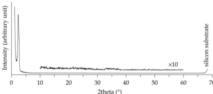
Wide-angle XRD measurements were performed to charac- terize the framework structure of CKU-F69. In the XRD pattern of most carbons, the Bragg diffraction peaks at around 2h= 26 and 45u arise from diffraction of graphitic (002) and (101) planes, respectively. However, no such peaks or even broad bands (which would appear in poorly ordered or very small domain size samples) were present in the XRD patterns of CKU-F69 carbonized even at 800uC (Fig. 9). This result may be explained by the crystallite size being too small to be detected by the wide-angle XRD, the pore wall being composed of glassy (amorphous) carbon, or the crystallites of carbon being oriented such that these diffraction peaks are not present in an XRD pattern. In the absence of information from the XRD measurements, Raman spectroscopy was used to determine the structure of the mesoporous carbon films because Raman spectroscopy has also been a useful tool for obtaining information on the microstructure of carbonaceous materials.36The spectra featured two major peaks centered at 1350 and 1580 cm21(Fig. 10), which are referred to as D and G bands, respectively, for sp2bonded carbon materials. The G band can be attributed to the in-plane carbon stretching vibrations of ideal graphene sheets, whereas the D band can be attributed to structural imperfection of graphene sheets. The degree of graphitization of carbonaceous materials is often estimated by the ratio of the intensity of the D band to that of the G band (ID/IG). The intensity ratiosID/IGincreased from 0.78 to 0.97 with increasing carbonization temperature, indicating that the pore wall of CKU-F69 became a poor Fig. 7 (a) Nitrogen adsorption (closed circle)/desorption (open circle)
isotherms and pore size distribution for CKU-F69 carbonized at 400 uC. (b) TGA curves of pure Pluronic F127 (dashed line) and resorcinol/phloroglucinol/Pluronic F127 (solid line) composite.
Fig. 8 (a–c) FESEM images of a cross section of CKU-F69 carbonized at 600uC. (d–f) TEM images of CKU-F69 carbonized at 400uC.
Fig. 9 Wide-angle XRD pattern of CKU-F69 carbonized at 800uC.
Fig. 10 Raman spectra of CKU-F69 carbonized at 600–800uC.
Downloaded on 08 November 2011 Published on 28 June 2007 on http://pubs.rsc.org | doi:10.1039/B705692C
graphitized carbon wall at elevated temperatures. The broad bands observed between 2300 and 3300 cm21, which are second order spectra, agree with this interpretation. These results indicate that CKU-F69 products consist of imperfect graphenes of a very small size (nanographenes)36,37 with no ordered stacking of graphitic (002) layers. In addition the most interesting band was observed at 450 cm21 for CKU-F69 carbonized at 800 uC, as indicated by the arrow in Fig. 10.
Low-frequency Raman bands like this can be considered as an indication of the existence of curved graphitic planes (single- wall carbon structure with nanoscale curvature), which was suggested by Kyotani’s group.37
Nitrogen adsorption/desorption analysis was carried out using films scratched from the substrate. Adsorption/desorp- tion isotherms shown in Fig. 7a yield typical type-IV curves with hysteresis loops which indicate large cage-like pore struc- tures in the materials. The BET surface area and the total pore volume of CKU-F69 carbonized at 400uC are 436 m2g21and 0.39 cm3g21, respectively. The pore diameters calculated from nitrogen adsorption and desorption isotherms were estimated as 4.7 and 3.7 nm, respectively. On the other hand, carbon films synthesized without F127 and carbonized at 400uC resulted in only a small amount of nitrogen adsorption, indicating poor porosity. Additionally, CKU-F69 carbonized at 300 uC also indicated no porosity as confirmed by nitrogen sorption.
Thermogravimetric analysis (TGA) shown in Fig. 7b was employed to investigate the degradation behavior of the F127 in the composite prepared using Res, Phl, and F127 under the nitrogen flow. We performed quantitative analysis using bulk powder samples because the sample weight was small due to thin film morphology. Below 300uC insignificant weight loss occurred, but a 45% weight loss occurred from 300 to 400uC, which is mainly attributed to the decomposition of F127.
Combined with nitrogen sorption, these results indicate that the porosity is generated by the decomposition of the F127. An additional weight loss of 15% occurred gradually between 400 and 800uC, which is attributed to the decomposition of some of the carbon precursor. This weight loss coincides with the shrinkage of the mesostructure framework and the decrease in the film thickness as determined by GISAXS. A possible formation process of CKU-F69 is as follows: in an acidic condition, resol-type phenolic resins, which are formed by polymerization of Res/Phl with formaldehyde and have a large number of hydroxyl groups, strongly interact with the hydro- philic PEO blocks of the F127 through hydrogen bonding interactions. Then, the ordered structure of organic–organic composites is generated after coating on the substrate and provided with porosity by carbonization at 300–400 uC. The thermosetting resins remained as the carbonaceous pore walls, while the F127 decomposed to form mesopores. Afterwards, in the carbonization stage up to 400 uC, the carbonaceous framework is provided with micro-porosity due to the generation of gases from the decomposition of the resins.
Conclusions
We demonstrate the formation of highly ordered mesoporous carbon films on several kinds of substrate through direct carbonization of organic–organic composite films. This
approach provides a simple route to fabricating mesoporous carbon and carbon–polymer materials with controlled morphology. The use of the different phenolic resin monomers has a favorable effect on the uniform and large area coatings of mesoporous carbon films and the stabilization of the ordered structure. The choice of an appropriate set of thermosetting polymers and thermally-decomposable organic templates is the most important factor in controlling the mesophase topologies and orientations of these ordered mesostructured carbons. We believe that this direct method will expand the possibility of synthesizing a variety of ordered porous carbon and carbon–polymer materials.
Acknowledgements
The authors thank Associate Prof. J. Hayashi (Chemical Reaction Engineering System Laboratory at Kansai University) for the nitrogen sorption measurements. S.
Tanaka acknowledges the Japan Society for the Promotion of Science (JSPS) Research Fellowships. Additionally, the GISAXS patterns were collected at the NSF funded facility for In-situ X-ray Scattering from Nanomaterials and Catalysts (MRI program award 0321118-CTS).
References
1 H. Marsh and B. Rand,Carbon, 1971,9, 63.
2 H. Tamai, T. Kakii, Y. Hirota, T. Kumamoto and H. Yasuda, Chem. Mater., 1996,8, 454.
3 Z. Hu, M. P. Srinivasan and Y. Ni,Adv. Mater., 2000,12, 62.
4 T. Kyotani, L.-F. Tsai and A. Tomita,Chem. Mater., 1995,7, 1427.
5 T. Kyotani, L.-F. Tsai and A. Tomita,Chem. Mater., 1996,8, 2109.
6 T. Kyotani,Bull. Chem. Soc. Jpn., 2006,79, 1322.
7 T. Kyotani, T. Nagai, S. Inoue and A. Tomita, Chem. Mater., 1997,9, 609.
8 Z. Ma, T. Kyotani and A. Tomita,Chem. Commun., 2000, 2365.
9 A. A. Zakhidov, R. H. Baughman, Z. Iqbal, C. Cui, I. Khayrullin, S. O. Dantas, J. Marti and V. G. Ralchenko,Science, 1998,282, 897.
10 J.-S. Yu, S. Kang, S. B. Yoon and G. Chai,J. Am. Chem. Soc., 2002,124, 9382.
11 R. Ryoo, S. H. Joo and S. Jun,J. Phys. Chem. B, 1999,103, 7743.
12 J. Lee, S. Yoon, T. Hyeon, S. M. Oh and K. B. Kim,Chem.
Commun., 1999, 2177.
13 S. Jun, S. H. Joo, R. Ryoo, M. Kruk, M. Jaroniec, Z. Liu, T. Ohsuna and O. Terasaki,J. Am. Chem. Soc., 2000,122, 10712.
14 J.-S. Lee, S. H. Joo and R. Ryoo,J. Am. Chem. Soc., 2002,124, 1156.
15 M. Kaneda, T. Tsubakiyama, A. Carlsson, Y. Sakamoto, T. Ohsuna, O. Terasaki, S. H. Joo and R. Ryoo,J. Phys. Chem.
B, 2002,106, 1256.
16 F. Kleitz, S. H. Choi and R. Ryoo,Chem. Commun., 2003, 2136.
17 Y. Xia, Z. Yang and R. Mokaya,Chem. Mater., 2006,18, 140.
18 A. Vinu, M. Miyahara and K. Ariga,Stud. Surf. Sci. Catal., 2005, 158, 971.
19 A. Vinu, P. Srinivasu, M. Takahashi, T. Mori, V. V.
Balasubramanian and K. Ariga, Microporous Mesoporous Mater., 2007,100, 20.
20 C. T. Kresge, M. E. Leonowicz, W. J. Roth, J. C. Vartuli and J. S. Beck,Nature, 1992,359, 710.
21 J. S. Beck, J. C. Vartuli, W. J. Roth, M. E. Leonowicz, C. T. Kresge, K. D. Schmitt, C. T. W. Chu, D. H. Olson, E. W. Sheppard, S. B. McCullen, J. B. Higgins and J. L. Schlenker,J. Am. Chem.
Soc., 1992,114, 10834.
22 D. Zhao, Q. Huo, J. Feng, B. F. Chmelka and G. D. Stucky,J. Am.
Chem. Soc., 1998,120, 6024.
23 J. Pang, X. Li, D. Wang, Z. Wu, V. T. John, Z. Yang and Y. Lu, Adv. Mater., 2004,16, 884.
24 S. Tanaka, N. Nishiyama, Y. Egashira and K. Ueyama,Chem.
Commun., 2005, 2125.
Downloaded on 08 November 2011 Published on 28 June 2007 on http://pubs.rsc.org | doi:10.1039/B705692C
View Online
25 Y. Meng, D. Gu, F. Zhang, Y. Shi, H. Yang, Z. Li, C. Yu, B. Tu and D. Zhao,Angew. Chem., Int. Ed., 2005,44, 7053.
26 F. Zhang, Y. Meng, D. Gu, Y. Yan, C. Yu, B. Tu and D. Zhao, J. Am. Chem. Soc., 2005,127, 13508.
27 Y. Meng, D. Gu, F. Zhang, Y. Shi, L. Cheng, D. Feng, Z. Wu, Z. Chen, Y. Wan, A. Stein and D. Zhao,Chem. Mater., 2006,18, 4447.
28 F. Zhang, Y. Meng, D. Gu, Y. Yan, Z. Chen, B. Tu and D. Zhao, Chem. Mater., 2006,18, 5279.
29 C. Liang and S. Dai,J. Am. Chem. Soc., 2006,128, 5316.
30 M. P. Tate, V. N. Urade, J. D. Kowalski, T. C. Wei, B. D. Hamilton, B. W. Eggiman and H. W. Hillhouse,J. Phys.
Chem. B, 2006,110, 9882.
31 S. Tanaka, M. P. Tate, N. Nishiyama, K. Ueyama and H. W. Hillhouse,Chem. Mater., 2006,18, 5461.
32 G. Wanka, H. Hoffmann and W. Ulbricht,Macromolecules, 1994, 27, 4145.
33 S. Besson, C. Ricolleau, T. Gacoin, C. Jacquiod and J.-P. Boilot, Microporous Mesoporous Mater., 2003,60, 43.
34 P. Falcaro, D. Grosso, H. Amenitsch and P. Innocenzi,J. Phys.
Chem. B, 2004,108, 10942.
35 V. N. Urade and H. W. Hillhouse,J. Phys. Chem. B, 2005,109, 10538.
36 A. C. Ferrari and J. Robertson,Phys. Rev. B, 2000,61, 14095.
37 J. I. Paredes, A. Martines-Alonso, T. Yamazaki, K. Matsuoka, J. M. D. Tascon and T. Kyotani,Langmuir, 2005,21, 8817.
Downloaded on 08 November 2011 Published on 28 June 2007 on http://pubs.rsc.org | doi:10.1039/B705692C