熊本大学学術リポジトリ
マグネシウム単結晶の疲労破壊挙動
著者 津志田, 雅之, 池田, 良介, 北原, 弘基, 安藤, 新
二
発行年 2009‑09‑03
URL http://hdl.handle.net/2298/13335
マグネシウム単結晶の疲労破壊挙動
津志田 雅之*1,池田 良介*2,北原 弘基*3,安藤 新二*3
*1熊本大学工学部技術部,*2熊本大学自然科学研究科院生,*3熊本大学自然科学研究科
1. 緒言
近年,マグネシウムは,軽量かつ高比強度材料として開発が進められている.このマグネシウムは結晶構造が hcp であ るためき裂方位により疲労破壊挙動が大きく異なると考えられる.ここで,このき裂方位依存性を明確にするためには単 結晶における調査が有効であるといえる.これまでにマグネシウム単結晶における疲労き裂伝ぱ機構を,単結晶 CT 試験 片を用いて調査した結果,結晶方位によって疲労き裂伝ぱ挙動が大きく異なることを確認している1- 2).
ここで,マグネシウム単結晶を用いてき裂の発生を含めた疲労強度における結晶方位依存性の調査を行う場合,従来の 疲労試験における試験片サイズの単結晶を確保するのはあまり容易なことではない.また,単結晶は変形し易く試験片作 製のための機械加工も問題となる.そこで,試験片サイズが小さく,かつ試験片形状が単純な試験片を用いた疲労試験機 を開発し,マグネシウム単結晶の疲労強度と疲労寿命における結晶方位依存性の調査を行った.
2. 実験方法
2.1 疲労試験片
本研究において市販のマグネシウムインゴットからブリッ ジマン法により単結晶を作製した. Fig. 1 に作製した疲労試 験片の形状を示す.20 mm×3mm×0.3 mm の試験片を切り出し,
化学研磨において表面を鏡面仕上げした.試験片の下端から 15 mmの位置に,き裂発生点とするための直径0.5 mm の円孔 をドリル加工により導入した.また試験片には,ステンレス 製のホルダーを,ホルダーの下端が円孔中心から1 mmの位置 になるように接着剤で取り付けた.今回2種類の方位の異なる 試験片を準備し,それぞれの試験片板面および荷重軸方向は,
(0001)[101
-2],および(101-2)[ 11
-00]とした.
2.2 疲労試験
Fig.1の試験片をスピーカのボイスコイル部に固定し,1次共
振振動させることにより,Fig.2に示すように試験片の円孔部 に曲げ応力を発生させることで平面曲げ疲労試験を行った.
ここで振動中の試験片下端より1mm上部の振幅Yをレーザ変 位計により測定し,その値から片持ち梁の曲げの式を用いて 円孔部に生じる曲げ応力を求めた.
h = 3EYL’ / {2L3-3L2 (L-L”) + (L-L”)3} (1)
ここで,Fig.2に示すように,Lを試験片ホルダーから試験片
下端までの長さ,L’を試験片の下端から円孔中心部までの長さ,
L”をホルダーからレーザ変位計による測定位置までの長さ,Y
Fig. 1 Shape and dimensions of fatigue test specimen of magnesium single crystal.
L”
L’L
Y
Laser displacement meter
Holder
Specimen
Hole part
Fig. 2 Positions of the hole and the measurement point of the displacement in the fatigue specimen.
を変位計測定位置での試験片の振幅,試験片の厚みをhとした.また,hcp金属単結晶のヤング率Eは結晶方位異方性をも つ3).その値を計算した結果,マグネシウムでは荷重軸が底面に平行であるA,B試験片では45.45GPaとなった.
2.3 応力評価
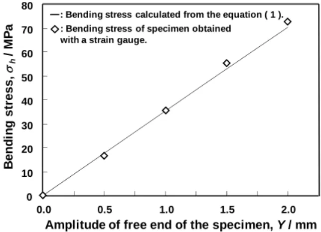
ここで,式(1)により応力を正しく評価できるかを確認 するために,円孔のない試験片とゲージ長さ2mmのひずみゲ ージを用いて,円孔位置(ホルダ端から1mm程度)にゲージ の中心が来るようにひずみゲージを取り付け,曲げひずみを 測定し,応力を評価した.その結果をFig.3に示す.式(1) において算出した応力とひずみゲージから求めた応力はこ の結果より,両者の値の差は2.8%程度であり,ほぼ等しい値 となった.
つぎに,円孔による応力集中の程度を有限要素解析ソフト
ANSYSを用いて評価した結果,応力集中係数は1.85となった
4).したがって,応力振幅aは次式により求めた.
a=h×1.85 ( 2 )
疲労試験は室温大気中で行い,繰り返し周波数1000Hz で行った.疲労試験後は破面をSEM により観察した.
3 実験結果
Fig. 4 に各試験片におけるa と破断までの繰返し数 Nfと
の関係(S-N 曲線)を示す.図中に矢印を付記したものはその 繰返し数において破断していないことを示している.この結 果より,いずれの試験片ともNf=107付近で疲労限を示してお り, A,B試験片の疲労限は40 MPaであった.また,一定 のa で比較するとA試験片に比べB試験片の疲労寿命は長 いことがわかる.このように疲労寿命には強い結晶方位の依 存性が確認された.
A試験片のき裂プロファイルにおいて.いずれの試験片に おいても,{101
-
2}双晶が発生していた.a = 92.5MPa において,き裂は[11
-
00]に沿って進展した.しかし,a=44.4MPa においてき裂は発生した{101
-
2}双晶のトレースに沿って進展した.すなわち,応力によりき裂進展機構が変化したことが わかる.
B試験片おいては,aに関係なく試験片表面において{101
-
2}双晶が観察され,き裂はジグザグに進展した.き裂が双晶 と交わるところでわずかに双晶トレースにそって進展する部分も観察されたが,大部分は双晶とは関係なく進展した.
以上のように,スピーカを用いた疲労試験機を開発し,マグネシウム単結晶における疲労破壊挙動の結晶方位依存性を 調査することができた.
参考文献
1) S.Ando,K.Saruwatari,T.Hori and H.Tonda,J. Japan Inst. Materals, 67, pp.247-251(2003).
2) S.Ando,Y.Ikejiri,N.Iida,M.Tsushida and H.Tonda,J. Japan Inst. Materals, 70, pp.634-637(2006).
3) R. W. Hertzberg, “Deformation and fracture mechanics of engineering materials”, pp.6-16 (1976) John Wiley & Sons.
4) M. Tsushida, K. Shikada, H. Kitahara, S.Ando and H.Tonda, Materials Transactions, 49, pp.1157-1161(2008).
120
100 80
60 40
20104 105 106 107 108 109 Number of cycles to failure, Nf/ cycles Stress amplitude,a/MPa A-specimen
B-specimen
Fig.4 S-N curves of A- and B-specimen.
: Bending stress calculated from the equation ( 1 ).
: Bending stress of specimen obtained with a strain gauge.
60 50 40 30 20 10 0
0.0 Bending stress, h/ MPa
Amplitude of free end of the specimen, Y / mm 70
80
0.5 1.0 1.5 2.0
Fig. 3 Comparison between the bending stresses calculated from the equation (1) and obtained with a strain gauge.