HDMI コネクタ (HDMI CONNECTOR) 1. 適用範囲 1.1 内容 本規格は HDMI コネクタの製品性能、試験方法、品質保 証の必要条件を規定している。 適用製品名と型番は 附表1の通りである。 1. Scope : 1.1 Contents
This specification covers the requirements for product performance, test methods and quality assurance provisions of HDMI connector.
Applicable product description and part numbers are as shown in Appendix 1. 2. 参考規格類 以下規格類は本規格中で規定する範囲内に於いて、本 規格の一部を構成する。万一本規格と製品図面の間に 不一致が生じた時は、製品図面を優先して適用するこ と。 万一本規格と参考規格類の間に不一致が生じ た時は、本規格を優先して適用すること。 2. Applicable Documents:
The following documents form a part of this
specification to the extent specified herein. In the event of conflict between the requirements of this specification and the product drawing, the product drawing shall take precedence. In the event of conflict between the requirements of this
specification and the referenced documents, this specification shall take precedence.
2.1 AMP 規格
A. 109-5000 : 試験法の一般条件 B. 501-5640-2, 501-5841-2 : 試験報告書
2.1 AMP Specifications :
A. 109-5000 : Test Specification, General Requirements for Test Methods B. 501-5640-2, 501-5841-2 : Test Report 2.2 民間団体規格
High Definition Multimedia Interface specification, Version 1.3a
2.2 Commercial Standards and Specifications High Definition Multimedia Interface specification version1.3a
3. 一般必要条件 3. Requirements : 3.1 設計と構造
製品は該当製品図面に規定された設計、構造、物理的 寸法をもって製造されていること。
3.1 Design and Construction :
Product shall be of the design, construction and physical dimensions specified on the applicable product drawing. 3.2 材 料 A. コンタクト リセプタクルシグナルコンタクト: 銅合金、接触部ニッケル上金メッキ及び結線部ニッケル 上金メッキ プラグシグナルコンタクト: 銅合金、接触部ニッケル上金メッキ及び結線部ニッケル 上錫メッキ B. ハウジング リセプタクルハウジング :熱可塑性樹脂:UL94V-0 プラグハウジング:熱可塑性樹脂:UL94V-0 C. その他 シェル:銅合金、錫メッキ 3.3 定 格 A.定格電圧 : 40V AC B.定格電流 : 0.5A C.使用温度範囲 : -25°C~+70°C 3.2 Materials : A. Contact
Receptacle Signal Contact:
Copper Alloy. Au over Ni plate on contact area and Au over Ni plate on soldering area.
Plug Signal Contact:
Copper Alloy. Au over Ni plate on contact area and Sn over Ni plate on soldering area.
B. Housing
Receptacle Housing : Thermoplastic UL94V-0 Plug Housing : Thermoplastic UL94V-0 C. Other
Shell : Copper Alloy, Sn plate 3.3 Ratings :
A. Voltage Rating : 40V AC B. Current Rating : 0.5A
C. Temperature Rating :-25°C to +70°C 3.4 性能必要条件と試験方法 製品は 表 1 に規定された電気的、機械的、及び耐 環境的性能必要条件に合致するよう設計されているこ と。試験は特別に規定されない限り室温下で行われるこ と。
3.4 Performance Requirements and Test Descriptions :
The product shall be designed to meet the electrical, mechanical and environmental performance
requirements specified in Table 1.
All tests shall be performed in the room temperature, unless otherwise specified.
3.5 性能必要条件と試験方法の要約
3.5 Test Requirements and Procedures Summary
項目 試験項目 規 格 値 試 験 方 法
Para. Test Items Requirements Procedures
製品の外観確認 性能上支障をきたす損傷の無
いこと。
目視により、コネクタの機能上支障をきた 損傷を検査する。
3.5.1
Examination of Product No physical damage Visual inspection No physical damage 機械的規格の確認 HDMI 規格,バージョン 1.3 に要 求される寸法を満足すること。 寸法検査は適当な測定器を用い実行され る。 3.5.2 Examination of Mechanical Specification
Dimensions required in the HDMI specification, version 1.3 shall be satisfied.
Dimensional inspection shall be
performed using suitable measuring tool 電 気 的 性 能 Electrical Requirements コンタクト及びシェル抵抗 初期値 コンタクト:50mΩ 以下 シェル:50mΩ 以下 嵌合コネクタを コンタクト: ANSI/EIA-364-23 オープンサーキット 20mV 以下,10mA シェル: ANSI/EIA-364-06A-83 オープンサーキット 5V 以下,100mA 3.5.3
Contact and Shell Resistance Initial Value Contact: 50mΩMax. Shell: 50mΩMax. Mated connector Contact : ANSI/EIA-364-23 Open circuit 20mV Max., 10mA Shell: ANSI/EIA-364-06A-83 Open circuit 5V Max., 100mA
耐電圧 沿面放電、フラッシュオーバー 等がないこと。 リーク電流 0.5mA 以下 ANSI/EIA-364-20, Method 301 未嵌合コネクタ: 500V AC 嵌合コネクタ: 300V AC 隣接コンタクト間及びコンタクト-シェル間 に上記電圧を 1 分間印加する。 3.5.4 Dielectric Withstanding Voltage No creeping discharge or flashover shall be occurred. Current leakage :
0.5mA Max.
ANSI/EIA-364-20, Method 301 Unmated connector: 500V AC Mated connector: 300V AC Apply a voltage above between
adjacent contacts and contact and shell for 1 minute. 絶縁抵抗 100MΩ 以上 (未嵌合コネクタ) 10MΩ 以上 (嵌合コネクタ) ANSI/EIA-364-21, Method 302 未嵌合コネクタ: 500V DC 嵌合コネクタ:150V DC 隣接コンタクト間及びコンタクト-シェル間 に上記電圧を 1 分間印加する。
3.5.5 Insulation Resistance 100MΩ Min.
(Unmated connector)
ANSI/EIA-364-21, Method 302 Unmated connector: apply 500V DC Mated connector: apply 150V DC
項目 試験項目 規 格 値 試 験 方 法
Para. Test Items Requirements Procedures
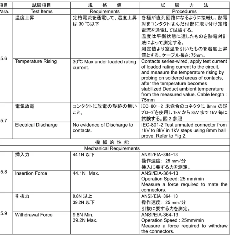
温度上昇 定格電流を通電して、温度上昇 は 30 ℃以下 各極が直列回路になるように接続し、熱電 対をコンタクトはんだ付部に取り付け定格 電流を通電して試験する。 温度は平衡状態に達したものを熱電対計 法によって測定する。 測定値より室温を引いたものを温度上昇 値とする。ケーブル長さ:75mm。 3.5.6
Temperature Rising 30℃ Max under loaded rating current.
Contacts series-wired, apply test current of loaded rating current to the circuit, and measure the temperature rising by probing on soldered areas of contacts, after the temperature becomes
stabilized Deduct ambient temperature from the measured value. Cable length : 75mm 電気放電 コンタクトに放電の形跡の無い こと。 IEC-801-2 未嵌合のコネクタに 8mm の球 プローブを使用し 1kV から 8kV まで 1kV 毎に 試験する。図 2 参照 3.5.7
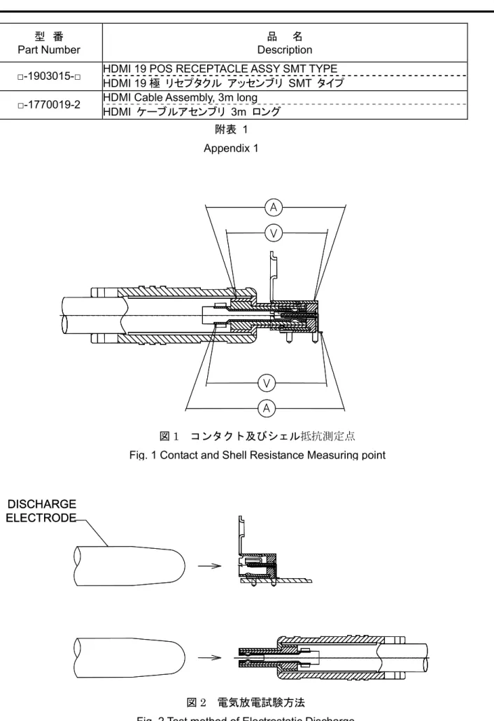
Electrical Discharge No evidence of Discharge to contacts.
IEC-801-2 Test unmated connector from 1kV to 8kV in 1kV steps using 8mm ball prove. Refer to Fig 2.
機 械 的 性 能 Mechanical Requirements
挿入力 44.1N 以下 ANSI/EIA-364-13
操作速度: 25 mm/分 挿入に要する力を測定。 3.5.8 Insertion Force 44.1N Max. ANSI/EIA-364-13
Operation Speed: 25 mm/min
Measure a force required to mate the connectors. 引抜力 9.8N 以上 39.2N 以下 ANSI/EIA-364-13 操作速度: 25 mm/分 引抜に要する力を測定。 3.5.9 Withdrawal Force 9.8N Min.
39.2N Max.
ANSI/EIA-364-13
Operation Speed : 25mm/min
Measure a force required to withdraw the connectors.
表 1 (続く) Table 1 (Cont.)
項目 試験項目 規 格 値 試 験 方 法
Para. Test Items Requirements Procedures
ケーブル屈曲 瞬断:1μsec 以下 耐電圧:項目 3.5.4 による。 絶縁抵抗:項目 3.5.5 による。 ANSI/EIA-364-41, Condition I 2 平面寸法の両方に 100 サイクル X=3.7x ケーブル径 円筒棒径:2.5×最大ケーブル径 曲げ角度:180°(片側 90°), 図 3 参照 電気的負荷: 試験中に DC100mA の電流 が負荷されること。
3.5.10 Cable Flex Discontinuity: 1µs Max. Dielectric Withstanding Voltage: Conform to item of 3.5.4 Insulation Resistance: Conform to item of 3.5.5 ANSI/EIA-364-41, Condition I
100 cycle in each of 2 planes dimension X=3.7 x Cable Diameter,
Roller Diameter: 2.5 x Max. Cable’s diameter.
Bend angle: 180°(90°on one side) Refer to Fig. 3
Electrical load: DC100mA current shall be flowed during the test.
耐久性 (繰り返し挿抜) コンタクト及びシェル抵抗: (試験後:初期からの変動値) コンタクト:20mΩ 以下 シェル:20mΩ 以下 挿抜回数: 10,000 回 自動サイクル, 100±50 サイクル/時 3.5.11 Durability (Repeated Mate / Unmating)
Contact and shell resistance: (after test: change from initial value)
Contact: 20mΩ Max. Shell: 20mΩ Max.
Durability: 10,000 cycles
Automatic cycling, 100±50 cycles/hour
振動 (高周波) 外観:項目 3.5.1 による。 コンタクト及びシェル抵抗: (試験後:初期からの変動値) コンタクト:20mΩ 以下 シェル:20mΩ 以下 瞬断:1μsec 以下
ANSI/EIA-364-28 ConditionⅢ Method 5A 振幅: 1.52mm P-P or 147m/s2{15G} 掃引時間: 20 分間で 50-2000-50Hz 期間: X.Y.Z 軸方向に各 12 回(計 36 回). 試験中に DC100mA の電流が負荷されるこ と。 3.5.12 Vibration (High Frequency) Appearance: Conform to item of 3.5.1 Contact and shell resistance: (after test: change from initial value)
Contact: 20mΩ Max. Shell: 20mΩ Max. Discontinuity: 1µsec maximum
ANSI/EIA-364-28 ConditionⅢ Method 5A
Amplitude: 1.52mm P-P or 147m/s2{15G}
Sweep time: 50-2000-50Hz in 20 min Duration: 12 times in each
(total of 36 times)X.Y.Z axes.
DC100mA current shall be flowed during the test.
項目 試験項目 規 格 値 試 験 方 法
Para. Test Items Requirements Procedures
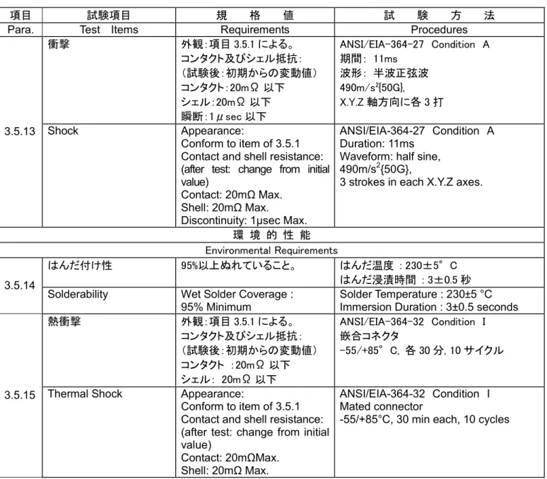
衝撃 外観:項目 3.5.1 による。 コンタクト及びシェル抵抗: (試験後:初期からの変動値) コンタクト:20mΩ 以下 シェル:20mΩ 以下 瞬断:1μsec 以下 ANSI/EIA-364-27 Condition A 期間: 11ms 波形: 半波正弦波 490m/s2{50G}, X.Y.Z 軸方向に各 3 打 3.5.13 Shock Appearance: Conform to item of 3.5.1 Contact and shell resistance: (after test: change from initial value)
Contact: 20mΩ Max. Shell: 20mΩ Max.
Discontinuity: 1µsec Max.
ANSI/EIA-364-27 Condition A Duration: 11ms
Waveform: half sine, 490m/s2{50G},
3 strokes in each X.Y.Z axes.
環 境 的 性 能 Environmental Requirements
はんだ付け性 95%以上ぬれていること。 はんだ温度 : 230±5°C
はんだ浸漬時間 : 3±0.5 秒 3.5.14
Solderability Wet Solder Coverage : 95% Minimum
Solder Temperature : 230±5 °C Immersion Duration : 3±0.5 seconds
熱衝撃 外観:項目 3.5.1 による。 コンタクト及びシェル抵抗: (試験後:初期からの変動値) コンタクト :20mΩ 以下 シェル: 20mΩ 以下 ANSI/EIA-364-32 Condition I 嵌合コネクタ -55/+85°C, 各 30 分, 10 サイクル
3.5.15 Thermal Shock Appearance:
Conform to item of 3.5.1 Contact and shell resistance: (after test: change from initial value)
Contact: 20mΩMax. Shell: 20mΩ Max.
ANSI/EIA-364-32 Condition I Mated connector
-55/+85°C, 30 min each, 10 cycles
表 1 (続く) Table 1 (Cont.)
項目 試験項目 規 格 値 試 験 方 法
Para. Test Items Requirements Procedures
湿度 A;外観:項目 3.5.1 による。 コンタクト及びシェル抵抗: (試験後:初期からの変動値) コンタクト: 20mΩ 以下 シェル: 20mΩ 以下 B;外観:項目 3.5.1 による。 耐電圧:項目 3.5.4 による。 絶縁抵抗:項目 3.5.5 による。 ANSI/EIA-364-31 MethodⅢ A;嵌合コネクタ B;未嵌合コネクタ +25~+85℃, 80~95%RH, 4 サイクル(96 時 間) 上記試験完了の後、試料は 24 時間室温 環境状態で調整され、その後規定された 測定が行われること。 3.5.16 Humidity A; Appearance: Conform to item of 3.5.1 Contact and shell resistance: (after test: change from initial value) Contact: 20mΩ Max. Shell: 20mΩ Max. B; Appearance: Conform to item of 3.5.1 Dielectric Withstanding Voltage: Conform to item of 3.5.4 Insulation Resistance: Conform to item of 3.5.5 ANSI/EIA-364-31 MethodⅢ A; Mated connector B; Unmated connector +25~+85℃, 80 to 95%RH, 4 cycles (96h)
Upon completion of the test, specimens shall be conditioned at ambient room conditions for 24h, after which the specified measurements shall be performed. 温度寿命 外観: 項目 3.5.1 による。 コンタクト及びシェル抵抗: (試験後:初期からの変動値) コンタクト: 20mΩ 以下 シェル: 20mΩ 以下 ANSI/EIA-364-17,Condition 4, Method A 嵌合コネクタ +105±2℃, 250 時間放置 上記放置期間完了の後、試料は 1~2 時 間室温環境状態で調整され、その後規定 された測定が行われること。
3.5.17 Thermal Aging Appearance:
Conform to item of 3.5.1 Contact and shell resistance: (after test: change from initial value)
Contact: 20mΩ Max. Shell: 20mΩ Max.
ANSI/EIA-364-17,Condition 4, Method A Mated connector +105±2℃, 250h Upon completion of the exposure period, the test specimens shall be conditioned at ambient room conditions for 1 to 2h, after which the specified measurements shall be performed.
リフローはんだ耐熱性 ハウジングの変形、溶け出しが なく、物理的損傷を生じないこ と。 予熱 150~180℃: 60~120 秒 加熱 230℃以上: 30~40 秒 ピーク温度 : 260℃ 温度は、本体部表面上とする。 リフロー回数: 2 回 プリント基板に取り付けて試験する。 図 4 参照 3.5.18
4. 製品認定試験の試験順序
4. Product Qualification Test Sequence
試験グループ/Test Group
1 2 3 4 5 6 7 8 9 10 11 12 13 試験項目 Test Examination
試験順序/Test Sequence (a) 製品の確認確認 Examination of Product 1,4,7 ,10 1,6,9 ,12 1,4,7 1,4,8 1,4 機械的規格の確認 Examination of Mechanical Specification 1 コンタクト及びシェル 抵抗
Contact and Shell Resistance 2,5,8 ,11 2,4,7 ,10,13 2,5 ,8 2,5 耐電圧 Dielectric withstanding Voltage 2,5 2 絶縁抵抗 Insulation Resistance 6,9 3 温度上昇 Temperature Rising 1 電気放電 Electrical Discharge 1 挿入力 Insertion Force 1 引抜力 Withdrawal Force 1 ケーブル屈曲 Cable Flex 1(b) 耐久性 (100 回) Durability (100 cycle) 3 耐久性 (10,000 回) Durability (10,000 cycle) 3 振動 Vibration 3(b) 衝撃 Physical Shock 6(b) 熱衝撃 Thermal Shock 3 5 3 湿度 Humidity 9(c) 11(c) 7(d) 温度寿命 Thermal Aging 6 8 はんだ付け性 Solderability 1 はんだ耐熱性(リフロ ー) Resistance to Reflow Soldering Heat 1
(a) 欄内の数字は試験の順序を示す。/Numbers indicate sequence in which the tests are performed. (b) 試験中瞬断の確認を行う。/ Measure discontinuity during the test.
(c) 両コネクタを未嵌合にて試験を行う。 (試験条件 B) / Unmated each connectors and test. (Test condition B) (d) コネクタを嵌合し試験を行う。(試験条件 A) / Mated connectors together and test. (Test condition A)
型 番 Part Number
品 名 Description HDMI 19 POS RECEPTACLE ASSY SMT TYPE □-1903015-□
HDMI 19 極 リセプタクル アッセンブリ SMT タイプ HDMI Cable Assembly, 3m long
□-1770019-2
HDMI ケーブルアセンブリ 3m ロング 附表 1 Appendix 1
図 1 コンタクト及びシェル抵抗測定点 Fig. 1 Contact and Shell Resistance Measuring point
DISCHARGE ELECTRODE
DISCHARGE ELECTRODE
ケーブル径に適合させる 内部ケーブル クランプの最近端 円筒棒 ケーブル固定保持具 図 3 ケーブル屈曲試験方法 Fig. 3 Test method of Cable Flex
260 230 180 150 30~ 40 60~120 図 4 リフロー温度プロファイル