its composites with unique nanostructure and
their application for supercapacitors with
high electrochemical performance
著者
ZHANG ZHIGUO
その他のタイトル
NiCo2S4とその複合体の合成、キャラクタリゼーシ
ョン及び高性能スーパーキャパシタへの応用
学位授与年度
平成29年度
学位授与番号
17104甲生工第309号
URL
http://hdl.handle.net/10228/00006819
Synthesis and characterization of NiCo
2S
4and its
composites with unique nanostructure and their
application for supercapacitors with high
electrochemical performance
Author: ZHANG ZHIGUO
Supervisor: Professor Tingli Ma
Graduate School of Life Science and System Engineering
Kyushu Institute of Technology
Abstract
Supercapacitors (SCs) have been attracting attention due to their high power density and safety. They have been widely used in various fields. However, the low energy density limits their application. According to the equation of E=1/2 CV2, the
high energy density can be achieved by enhancing specific capacitance and broadening operating voltage. Hence, great efforts have been focused on optimizing the electrode material and assembling asymmetric supercapacitors.
Generally, faradaic electrode materials possess higher specific capacitance than carbon-based materials attributed to the redox reaction. The faradaic materials include conducting polymers and transition metal oxides/sulfides. However, the conducting polymers inevitably swell and shrink during the redox reaction process, it can lead to poor stability and limited capacitance. Therefore, the transition metal oxide is a promising candidate. However, the intrinsically slow kinetic and poor electrical conductivity of transition metal oxides result into low rate-capability, which restrict their practical application. In order to achieve a high capacitance and desirable rate performance, development of the electrode materials with high conductivity is required.
On the other hand, transition metal sulfides have good conductivity. Among many kinds of transition metal sulfides, NiCo2S4 is a great potential candidate due to its
metallic conductivity, controllable morphology and high capacitance. Therefore, this thesis mainly focuses on the NiCo2S4 and NiCo2S4-based composites for
high-performance SCs. The NiCo2S4 and its composite are synthesized by a simple
method and controlled their nanostructure from 1D to 3D. The asymmetric flexible and solid-state supercapacitors are also assembled. The results of electrochemical measurements indicated that NiCo2S4@VS2 and NiCo2S4@MnS composites are great
potential for energy storage systems.
energy storage mechanism of SCs is also given in detail. The previous studies of electrode materials are introduced. In the end of this chapter, the research purpose is presented.
In chapter 2, the reagents and apparatus used in this work are summarized. The physical and chemical characterizations are carried out, including X-ray diffraction (XRD), scanning electron microscopy (SEM) and transmission electron microscopy (TEM). The electrochemical measurements based on cyclic voltammograms (CV) and galvanostatic charge-discharge (GCD) are also explained.
In chapter 3, several materials of NiCo2S4 with different morphologies are
synthesized. The growth mechanism is deduced. Compared to the needle (1D) and flake (2D) structures, the 3D honeycomb NiCo2S4 shows an excellent electrochemical
performance. The maximum specific capacitance is up to 7.4 F cm-2 at a current
density of 1 mA cm-2. The specific capacitance remains 99% of the initial capacitance
at a current density of 10 mA cm-2, indicating that 3D honeycomb NiCo2S4 has good
stability.
In chapter 4, the NiCo2S4@VS2 with unique structure on Ni foam is prepared by a
simple in-situ hydrothermal method and one-step sulfurization. Highly conductive NiCo2S4 nanoneedle arrays are in situ grown on 3D sponge-like Ni foam, which expose
accessible sites for growing ultrathin VS2 nanosheets, resulting into desirable rate
capability and remarkable cycle performance. The prepared NiCo2S4@VS2 displays a
high specific capacitance of 1968 F g-1 due to the synergetic effects. In addition,
aqueous asymmetric SCs are assembled based on NiCo2S4@VS2 and active carbon.
The operating potential of devices is enlarged to 1.55 V. A maximum energy density of 31.2 Wh kg-1 is achieved at the power density of 775 W kg-1. The device also shows
high-rate capability under different current densities.
In chapter 5, the NiCo2S4@MnScomposite is prepared and their properties are
studied. The carbon cloth is used as substrate owing to the good conductivity and mechanical strength. Additionally, an solid-state flexible asymmetric SC is fabricated
using NiCo2S4@MnS/carbon cloth as positive electrode, active carbon/carbon cloth as
negative electrode and poly(vinyl alcohol)/KOH gel as electrolytes, respectively. The device shows an energy density of 23.3 Wh kg-1 at a power density 725 W kg-1 and a
maximum power density was 7.25 kW kg-1 at an energy density of 5.11 Wh kg-1 in a
potential range of 0-1.45 V. The solid-state asymmetric supercapacitor has excellent mechanical flexibility. These results suggest that the NiCo2S4@MnS composite hold a
great potential for energy storage applications.
Finally, general conclusions and future prospects are described. The investigations of NiCo2S4 and NiCo2S4 based composites are carried out from two aspects of
synthesis method and electrochemical performance. The further studies need to focus on exploring the new materials and fabricating new structure device with high-performance.
I
Table of contents
Chapter 1 Introduction ... 1
1.1 Background ... 1
1.2 Structure and Fundamental of Supercapacitors ... 3
1.3 Performance Evaluation ... 5
1.4 Electrode materials of Supercapacitors ... 5
1.4.1 Carbon materials ... 6
1.4.2 Metal oxides ... 10
1.4.3 Conducting polymers ... 12
Reference ... 15
Chapter 2 Experimental section ... 17
2.1 Instruments and reagents ... 17
2.1.1 Instruments ... 17
2.1.2 Reagents and materials ... 18
2.2 Characterization ... 18
2.2.1 X-Ray Powder Diffraction (XRD) ... 19
2.2.2 X-Ray Photoelectron Spectroscopy (XPS) ... 19
2.2.3 Field Emission Scanning Electron Microscopy (FESEM) ... 19
2.2.4 Transmission Electron Microscopy (TEM) ... 19
2.3 Electrochemical measurements ... 20
2.3.1 Measurement basis ... 20
2.3.2 Cyclic Voltammogram (CV) ... 22
2.3.3 Galvanostatic Charge-Discharge (GCD) ... 23
2.3.4 Electrochemical impedance Spectroscopy (EIS) ... 24
Reference ... 26
Chapter 3 The growth mechanism of NiCo2S4 and the electrochemical performance in supercapacitors ... 27
II
3.2 Experimental ... 28
3.2.1 Pretreatment of Ni foam ... 28
3.2.2 Preparation of NiCo2S4 with different morphologies ... 29
3.2.3 Characterization ... 29
3.2.4 Electrochemical measurements ... 30
3.3 Results and discussions ... 30
3.3.1 Characterization of morphology ... 31
3.3.2 Characterization of chemical composition ... 36
3.3.3 Schematic illustration of mechanism ... 37
3.3.4 Investigation of electrochemical performance ... 40
3.4 Conclusion ... 48
Reference ... 49
Chapter 4 NiCo2S4@VS2 with core-shell structure for high-performance asymmetric supercapacitors ... 51
4.1 Introduction ... 51
4.2 Experimental ... 52
4.2.1 Preparation of VS2 ... 53
4.2.2 Preparation of NiCo2S4 and NiCo2S4@VS2 ... 53
4.2.3 Preparation of negative electrode ... 53
4.2.4 Materials characterization ... 54
4.2.5 Electrochemical measurements ... 54
4.3 Results and discussions ... 55
4.3.1 Characterization of morphology ... 55
4.3.2 Characterization of chemical composition ... 58
4.3.3 Investigation of electrochemical performance ... 59
4.4 Conclusion ... 64
Reference ... 65 Chapter 5 Solid-state flexible asymmetric supercapacitors with high energy
III
and power densities based on NiCo2S4@MnS and AC ... 67
5.1 Introduction ... 67
5.2 Experimental ... 69
5.2.1 Pretreatment on carbon cloth ... 69
5.2.2 Preparation of MnS/CC, NiCo2S4/CC and NiCo2S4@MnS/CC . 69 5.2.3 Preparation of negative electrode ... 70
5.2.4 Preparation of KOH/PVA gel ... 70
5.2.5 Characterization ... 70
5.2.6 Electrochemical measurements in 3-electrode ... 71
5.2.7 Electrochemical characterization of assembled asymmetric supercapacitors ... 71
5.3 Results and discussions ... 71
5.3.1 Characterization of morphology ... 71
5.3.2 Characterization of chemical composition ... 78
5.3.3 Investigation of electrochemical performance ... 79
5.4 Conclusion ... 89 Reference ... 90 General conclusions ... 92 Future prospects ... 94 Achievements ... 95 Publication ... 95 Conference presentation... 95 Acknowledgements ... 96
1
Chapter 1 Introduction
1.1 Background
The development of human society is closely linked with the energy sources. Especially in the 21st century, the demand for energy becomes overwhelming.
However, it inevitably brings some problems related to human survival, such as air pollution and global warming because of the dependence on fossil fuels[1]. Therefore, how to effectively get unlimited and sustainable energy as well as friendly to the environment is very important. As a result, researchers have just turned their attentions to solar energy, wind energy and nuclear energy[2-3].
It is known that most of new energy plants are always placed in remote or hostile regions. So the question is how to save and deliver the energy safely. There is an urgent demand for technologies related to energy conversion and storage. Presently, energy conversion/storage systems are batteries and supercapacitors (SCs).
Rechargeable batteries, especially Lithium ion batteries (Li-ion batteries) are extensively used in our daily life, such as smartphone, electric car, wind power generation, even in aerospace and other military fields. It is believed that Li-ion battery is one of the most promising energy storage systems. However, it has gradually exposed some demerits, such as relative low power density and poor cycle stability.
To solve these problems, researchers have investigated alternative materials such as carbon-based materials, polymers and so on[1]. Different materials with different nano structure were prepared to increase power density and reduce the cost along with better stability, but it does not achieve desired results after much efforts[4-6]. In this context, it has been expected that SCs can provide extreme cycle life and high energy density comparable to Li-ion batteries.
2
Table1 Ragone comparison of three kinds of energy storage systems[1,7-9] Power density (W kg-1) Energy density (Wh kg-1)
Traditional capacitors 104-107 <0.05
Rechargeable batteries <500 20-200 Supercapacitors 102-104 <10
Table2 Performance comparison of rechargeable batteries and supercapacitors[1,8-9] parameters Rechargeable batteries Supercapacitors Discharge time hours minutes
Charge time hours minutes Coulombic efficiency 0.7-0.85 0.85-0.98
stability <2000 >105 Temp range -20-60℃ -40-70℃
Cost/kWh 104€ 200-103€
Risk of explosion yes no Life 5-10 years 10-15 years Maintenance Need No need Storage mechanism chemical physical
Power limitation reaction kinetics,
mass transport conductivity Energy storage high (bulk) limited (surface area)
Charge rate kinetically limited high Cycle life limitations mechanical stability
chemical reversibility side reactions From the Table 1, it can be observed that SCs have higher energy density than traditional capacitors and higher power density than rechargeable batteries. Even though the energy density of SCs is limited when compared to Li-ion batteries, it can be employed as back-up storage device. The relevant parameters of Li-ion batteries and SCs are listed in Table 2. Compared to Li-ion batteries, the drawback of SCs is its
3
relatively low energy density, which limits its widespread application. That is why Li-ion batteries are not totally substituted by SCs. SCs have many merits such as fast charge rate, friendly to environment, safety, low cost and long-term stability even in some severe conditions[10-12]. Just because of these advantages, SCs have been attracting much attention. Although the energy density of SCs is less than 10 Wh kg-1,
they are widely applied as back-up power sources in many fields.
The first patent of SC was filed as early as 1957, but it has not been drawn attentions until in the 1990s. Increasingly, SCs are expected to be back-up power for batteries in many fields. Hence, SCs gradually occupy part market. The estimated value of global market for SCs was about $684.7 million in 2016, and it is expected to be up to $2096.16 million in 2022[1]. The cost of batteries is 10-50 times more expensive than that of SCs from the aspect of gravimetric energy, but there is a great potential to reduce the cost of SCs for its extensive application[5,13-15].
1.2 Structure and Fundamental of Supercapacitors
Great progresses have been yielded whether in the theoretical research or practical application. The structure and relevant fundamentals related to SC are also figured out. Similar to batteries, SCs are mainly composed of two electrodes (positive and negative electrodes), a separator (avoiding short circuit) and an electrolyte (conduct electricity and taking part in the reaction)[1,5,16]. Generally, separators are fabricated by polyethylene and polypropylene. As electrolytes for SCs, they should be born with low resistivity, good electrochemical stability, wide working potential window, and low cost [4,7,11,16]. Certainly, electrolytes can`t react with electrode materials and current collectors. Aqueous electrolyte, ionic liquid and organic electrolyte are the most common electrolyte types[12,17-18].
4
Table 3 Comparison of selected electrolytes[1] Window (V) De/merits
Aqueous 1.2 Higher ionic concentration, lower resistance Ionic liquids 4.5 High thermal and chemical stability
Organic 3.5 Good conductivity, wide temperature range In spite of the relative narrow potential window of aqueous electrolytes, they still have been applied into variety of fields. Generally, aqueous electrolytes could be further classified into acid, neutral and alkaline electrolytes[1,5,8,14,19]. Therefore, they can almost meet all kinds of conditions. Compared with organic electrolytes, the concentration of aqueous electrolytes can be optionally controlled, along with lower resistance[1,20-21]. Aqueous electrolyte-based SCs could sometimes show higher power density and specific capacitance than those SCs containing organic electrolytes, probably because of the high ionic concentration and small ionic diameter[1]. Different with organic electrolytes, the preparing process of aqueous electrolytes is very easy and almost has no requirements[14,22-24]. SCs with aqueous electrolytes can work in room temperature and air condition. In terms of cost and compatibility, KOH is selected as electrolytes in our research system.
As the most important component in SCs, electrode materials are widely studied. According to the storage mechanism involved inside electrode materials with electrolytes, SCs can be categorized as double layer capacitors (EDLCs) and pseudocapacitors[1]. Compared with the traditional dielectric capacitors that store charges on big plates but with low surface area, EDLCs store charges in a double layer built by opposite polar ions between electrode materials and electrolytes when the EDLCs are charged[5-6,8,16]. While, the process is reversed as EDLCs are discharged. In general, electrodes are prepared from nanosized materials who have large surface and good conductivity[1]. In addition, the distance of the double layer is
5
several angstroms. According to the formula, C =4𝜋𝑑𝐴𝜀, where A stands for the active surface area of electrode, εis the electrode dielectric constant and d is the thickness of the double layer, EDLCs could show remarkable specific capacitance. During the charge process, the negative and positive charges are equally separated on the interface between electrode and electrolyte[2,19,25-28]. Actually, two EDLCs are created, which is connected in series. There are no redox reactions involved no matter in charge or discharge processes, therefore this kind of supercapacitors holds outstanding cycle stability. Because of the electrostatic interaction, the specific capacitance is limited. Pseudocapacitors store energy through highly reversible redox reactions, accompanied by electric double layer storage[24,29]. Hence, pseduocapacitors have higher specific capacitance than that of EDLCs.
1.3 Performance Evaluation
In this section, we mainly focus on the evaluation in terms of electrochemical performance. The proper-evaluating parameters include cyclic voltammograms (CV), galvanostatic charge-discharge curves (GCD), rate capability, coulombic efficience, ragone plot, cycle test, and electrochemical impedance spectroscopy (EIS) as well as Bode and phase test. The relevant mechanism and analysis method will be stated in Chapter 2 in details.
6
Fig. 1 The classification of electrode materials and supercapacitors
As described above, SCs can be classified into EDLCs and pseudo-capacitors as well as hybrid capacitors according to the mechanism involved inside electrodes. Therefore, it is necessary to discuss materials based on the mechanism. As mentioned in Fig. 1, carbon materials, conducting polymers and metal oxides/sulfides are frequently employed in SCs.
1.4.1 Carbon materials
The first commercial supercapacitor is carbon-based capacitor[1]. As we discussed, the capacitance of EDLCs is closely related to the surface area of active materials. Carbon materials have many advantages such as high surface area, low cost, non-toxicity, good conductivity and outstanding stability[5-8,16,30]. Based on these merits, carbon materials are desirable candidate for EDLCs so far. It is proved that surface area, pore size distribution, functional groups and heteroatoms have influence on the electrochemical property[1]. Much effort has been made to increase the surface area, including KOH activation and alkaline treatment. These methods can effectively introduce micropore into active carbon. Notably, it does not mean the bigger the specific surface area, the higher the specific capacitance. It is because not all pores can take part in the “reaction” with electrolytes[1]. Apart from the conductivity and surface area, the capacitance depends on the pore size distribution. As we know that carbon materials, especially active carbon, have different types of porosity. They can
7
be divided into micro-(<2 nm), meso-(2-50 nm) and macro-pores (>50 nm). In general, different pores have different effects for the electrochemical performance[1,9,13,30].
To some extent the specific capacitance increases with the increasing of microporous ratio[12,20-21]. However, increasing the amount of micropores may bring some negative effects, leading to poor volumetric capacitance and poor conductivity. Furthermore, mesopores play a key role in the electrochemical performance, especially in the form of ordered and interconnected networks[14,16,31-32]. Particularly, highly accessible surface with meso-structure is needed, because they can provide high power density with good capacitance retention[1,15,32]. It is believed that macropore can be seemed as “reservoir” for reaction. On the basis of the compatibility between electrolyte ions and pores, reasonable pore distribution can achieve a maximum specific capacitance. A lot of researchers have prepared carbon materials with desirable pore size distribution and high surface area by template method or other ways[1].
Recently, introducing functional groups or heteroatoms (N, O B S) is also an effective way to increase the capacitance of carbon materials[20-21]. It is accepted that these functional groups and heteroatoms can participate in redox reactions, leading to the improvement of specific capacitance. Meanwhile, they enhance wettability and accelerate ion transports, which is helpful for the cycle stability and power density.
However, introducing surface functional groups will increase the resistance and may induce adverse consequences, leakage and electrolyte decomposition.
Usually, active carbon (AC), carbon aerogel, carbon nanotube (CNT) graphene/oxides are frequently used as EDLCs electrode materials. As the widest used materials, AC is always obtained from carbon precursors by carbonization and activation treatment[1,8,12,16]. These carbon precursors are in rich carbon element, sometimes with nitrogen element. Some carbon-rich precursors are listed in Table 4 as
8
well as the (Brunauer-Emmett-Teller BET) specific surface area (SSA). To date, preparing AC with suitable pore size distribution and a high surface area from carbon/nitrogen-rich precursor is still an main way for high performance electrode materials[1].
Table 4 Surface area of AC from different carbon precursors[1]
Precursor SSA (m2 g-1) Precursor SSA(m2 g-1)
Furfurol 1040 Coconut shell 1660 Rice husk 1890 Bamboo 1290 Starch 1510 Corn grain 3200 Apricot shell 2335 Sucrose 2100 Banana fiber 1100 Fish scale 2270
Carbon aerogels are another kind of potential materials for EDLCs because of their high conductivity (100 S cm-1), controllable pore size distribution and high
surface area, reached to 1100 m2 g-1[1,8,12]. The physical and chemical properties of
carbon aerogels are always adjusted by the reactants and catalyst used in the preparation process. The specific capacitance of 215 F g-1 was reported in a
3-electrode configuration from resorcinol-formaldehyde[1]. Recently, attentions are paid to graphene-based EDLCs due to good conductivity, large surface area, good physical and chemical stability, regulated surface functional groups and flexibility. It was reported that a high specific capacitance of 205 F g-1 is realized in aqueous
electrolyte[1]. However, graphene, a sheet of sp2 carbon atoms, has a tendency to
restack because of the van der waals interaction, which inevitably leads to lower power density and poor cycle stability[7-9,13,21,31,33]. An effective way to solve this problem is to combine with other materials, such as pseudocapacitive substance[1]. CNTs come to be known for the special mechanical and conductive properties. Additionally, CNTs are born with high surface area and mesopores which are favored [6-7,16,34]. CNT-based SCs exhibited a large energy density of 7 Wh kg-1
9
as carbide derived carbons, carbon fibers and so forth. Table 5 summarizes the electrochemical performance of different carbon materials.
Table 5 Summary on the carbon materials and their electrochemical performances[1] materials electrolyte Highest
capacitance
Current
density(A g-1) Ref.
Mesoporous graphene EMIMBF4 250 F g-1 1 [6]
Graphene hydrogel PVA/H2SO4 186 F g-1 1 [23]
Carbon naosheets EMIMBF4 242 F g-1 1 [20]
N-carbon spheres 6 M KOH 194 F g-1 0.5 [28]
Nanoporous carbon EMI-TFSI 178 F g-1 0.5 [35]
Carbon nanowhiskers 6 M KOH 210 F g-1 0.5 [18]
Mesoporous carbon TEABF4/AN 130 F g-1 0.1 [24]
Porous carbon/CNTs 3 M H2SO4 237 F g-1 0.1 [14]
Carbon foams 6 M KOH 203 F g-1 0.5 [15]
Carbon hydrates 5 M KOH 140 F g-1 1 [17]
Hollow nanocarbon 1 M KOH 183 F g-1 1 [21]
Graphene-coated CNTs EMI-TFSI 130 F g-1 0.1 [25]
Graphene/CNF 1 M H2SO4 174 F g-1 0.2 [29]
Graphene/carbon EMIMBF4 190 F g-1 1 [7]
RGO/CNT PVA/H3PO4 252 F g-1 0.5 [26]
RGO/carbon black PVA/H3PO4 79 F g-1 1 [26]
RGO PVA/H3PO4 4.04 mF cm-2 1 [16]
Activated MESO BMIM TFSI 200 F g-1 0.7 [5]
Activated graphene 1 M H2SO4 240 F g-1 1 [19]
Activated 3D graphene EMIMBF4 231 F g-1 1 [32]
Activated MESO BMIM BF4/F 172 F g-1 1 [36]
However, carbon materials suffer from the low specific capacitance. They are often combined with conducting polymer or transitional metal oxides/sulfides to
10
improve their energy densities.
1.4.2 Metal oxides
As mentioned above, EDLCs suffer from specific capacitance, limiting their wide application. The specific capacitance of pseudocapacitors can be ~100 times higher than that of EDLCs[1]. As a consequence, substantial efforts have been made to develop kinds of pseudocapacitive electrode materials with various morphologies. The research of metal oxides and sulfides are quite active due to their large specific capacitance[1,15,18,23,25,29,32,35]. Among them, RuO2, NixOy, CoxOy and RuO2 are
extensively investigated. The metals inside those materials always have at least 2 valences which can coexist in a fixed range [1].
RuO2 is the one which possesses both good conductivity and high specific
capacitance among the metal oxides for supercapaictors. It also has relatively wide working window, highly reversible redox reactions and stability. Besides, RuO2 with
three oxidation states has a high specific capacitance, up to 1000 F g-1. Remarkably,
RuO2 can show satisfied electrochemical performance in acidic and alkaline
electrolytes[1,9-10,19,23,25]. In acidic electrolyte, Ru can vary between Ru2+ and
Ru4+. Specific capacitance ca. 600 F g-1 was reported in acidic medium. However, in
alkaline solutions, it is believed that RuO2, RuO42- and RuO4- coexist in the redox
reactions. Crystal water in RuO2xH2O has influence on its specific capacitance.
Typically, specific capacitance has a proportional relationship with the increasement of x values[1]. Scientists try to seek other traditional metal oxides or preparing RuO2-based composites because RuO2 is too expensive and environmental harmful to
be extensively used as electrode materials. MnO2 seems to be an alternative candidate
for RuO2 thanks to the low cost and high theoretical capacitance (1100-1300 F g-1)[1].
Similar to RuO2, the main mechanism of MnO2 involved in energy storage is
reversible redox reactions. The exchange of protons and cations with the electrolytes takes place during the electrochemical process, along with transitions between various oxidation states. The relevant mechanism can be descripted as followings:
11
MnOα(OC)β + δC+ + δe+ ↔ MnOα-β(OC)α+β
where C+ stands for the protons and alkaline metal cations (Li+, Na+, K+) in the
medium solution, and MnOα(OC)β, MnOα-β(OC)α+β represent MnO2.nH2O in high
and low states, severally. Like RuO2, the cyclic voltammetry curves and galvanostatic
charge-discharge curves of MnO2-based SC are analogous to EDLCs. Meanwhile,
their pseudocapacitive manifestations are controlled by several physical and chemical factors, such as the chemical hydrous state, crystallinity, crystal structure, morphology, thickness of the layer, surface area, pore structure and so on[1].
To obtain desirable MnO2 electrode, researches have to compromise all kinds of
aspects. For MnO2, a lethal issue is the poor electronic conductivity, which limits the
power density and energy density. Introducing carbon materials or doped with metal could increase its accessible surface area and facilitate ion transport[4,10,27-28]. For example, Ni-doped MnO2 in nanoscale can increase surface area by 46% and the
capacitance by 37%[1].
As pseudocapacitive electrode materials, Co-based oxides and hydroxides have received significant attentions, especially Co3O4 due to its remarkable reversibility
and extreme theoretical specific capacitance, up to 3560 F g-1. With respect to this, it
has been once seemed as promising materials for SCs. Co3O4 with designed
morphologies have been synthesized and applied for SCs. We all know that Co3O4 is
p-type semiconductor, which suffer from poor limited conductivity. Furthermore, most researches focus on the synthesis of nano-sized Co3O4, such as nanorods,
nanosheets and nanowires[1]. In this way, the ion distance becomes shorter, further improving the utilization of Co3O4. Other alternative method is combining with some
conductive additives, such as carbon materials and metals. Same as cobalt oxides, nickel oxides are low cost, environmental friendliness and easier to synthesize. Additionally, NiO is not only stable in KOH electrolytes, but also has ultrahigh theoretical specific capacitance of 3750 F g-1. It is believed that the electrochemical
12
synthesizing NiO. According to the reports, 300-350oC is often selected as calcination
temperature[4,19,27-28]. As mentioned above, NiO electrode materials also suffer from high resistivity. Another challenge is its poor cycle stability. To obtain satisfactory electrochemical results, nanosized and hierarchical porous NiO electrodes were prepared, which can accelerate the transportation of electrolyte ions and shorten the diffusion distance, contributing to high specific capacitance and rate capability as well as longer cycle life[1]. Other alternative way is to introduce metals into nickel oxides matrix, such as Ni, Mn, Co and so on. Actually, transitional hydroxides also could show satisfactory electrochemical performance. However, they are still trapped by the low conductivity, which can be alleviated by the same methods discussed above. Remarkably, a recent trend is to develop transitional metal sulfides for SCs thanks to their better conductivity and high specific capacitance than that of transitional metal sulfides[1,3,18,28,32]. They will be discussed in Chapter 3 in detail. Here, all these redox reactions involved in transitional metal oxide and transitional metal hydroxides are given in follows:
Co3O4 + H2O + OH- ↔ 3CoOOH + e-
Co(OH)2 + OH- ↔ CoOOH + H2O + e
-CoOOH + OH- ↔ CoO
2 + H2O + e
-NiO + OH- ↔ NiOOH- + e-
There are other materials exhibiting pseudo-capacitive properties, such as Sn-based, Nb-based, V-based, Fe-based, Mo-based and so on. Ni, Co, Mn based transitional oxides/hydroxides/sulfides/ are frequently studied and show better electrochemical results than others. So other metal oxides are not discussed due to the limited space.
1.4.3 Conducting polymers
Another important type pseudocapacitve electrode material is conducting polymers. They have many merits, such as high conductivity (up to 104 S cm-1 for
13
accompanied with regulated pseudocapacitive activity[1,31,33]. All these prominent advantages endow them as promising electrode materials for SCs. Their specific capacitance is almost from redox reactions, and redox reactions occur through the whole bulk, not only just on the surface area/near surface area[2,4,19,27]. During the reaction process, there are no structure or phase changes, ascertaining its high reversibility. Generally, conducting polymers mainly include poly (3, 4-ethylenedioxythiophene) (PEDOT), polypyrrole (PPy), polyimides (PI), polythiophene (PTh), polyaniline (PANI) and polyacetylene (PA)[1]. Remarkably, conducting polymers can be regulated into negative or positive charge by inserting ions into its matrix. As a consequence, delocalized n electrons in the polymer chains are generated, inducing high conductivity. The positively and negatively charged polymers are named as P-doped and N-doped polymers, severally. The potentials of P-/N-doped polymers are controlled by π electrons. In the family of polymers, PANI and PPy are usually P-doped, and often used as positive electrode in asymmetric SCs[3,13,20,30-31,33,37]. By the way, the electrolytes of PANI-based supercapacitors are proton-rich medium, such as acidic solution or protic solvent. In addition, the conductivity of N-doped polymer is limited, which is much more pronounced at more negative potentials, leading to a low specific capacitance. There are many papers about conducting polymers for SCs[11,31,33]. PANI hydro gel have been prepared and showed 750 F g-1 at current density of 1 A g-1. PPy deposited on
steel mesh exhibited a capacitance of 170 F g-1 at a current load of 0.5 A g-1.
Unfortunately, conducting polymers suffer from mechanical degradation because of swelling and shrinking in the intercalating/deintercalating process, leading to poor stability[1,30,36]. A promising method to improve the electrochemical performance of conducting polymers is to combine with carbon materials or other species from the aspects of electrical conductivity, mechanical stability and chain structure. A summary of conducting polymer based SCs is give in Table 6.
14
composite Capacitance
(F g-1) Electrolyte Potential (V) Ref.
PEDOT/PPy 290 1 M KCl -0.4-0.6 [38] PPy/MWNTs 320 1 M H2SO4 0-0.6 [33] PPy/CNTs 87 1 M LiClO4 0-1.0 [22] PPy/carbon 4333 6 M KOH -1-0 [4] PPy/graphene 165 1 M NaCl 0-1.0 [31] PPy/MCNTs 4273 1 M Na 2SO4 -0.4-0.6 [12] PANI/MWNTs 344 1 M H2SO4 0-0.6 [37] PANI/graphene 3203 2 M H2SO4 0-0.8 [30] PANI/Si 4093 1 M H 2SO4 0-0.8 [3] PANI/Ti 7403 1 M H2SO4 -0.2-0.8 [11] PPy/RuO2 3023 1 M H2SO4 -0.2-0.7 [10]
It should be noted that all conducting polymers seem active in a narrow potential window. The conducting polymers may degrade or insulate beyond this specified working window[11,31,33].
In this section, we take into account different electrode materials and corresponding electrolytes, meanwhile summarize the de-/merits and provide paralleling solutions. For carbon material, high accessible surface and rational pore distribution are desirable. Apart from these requirements, combining with other pseudocapacitive materials is equally important to achieve high energy density in terms of commercial applications[17,26,32]. With respect to conducting polymers, the key point is how to alleviate the swelling and shrinking during the cycling performance. Regarding to transitional metal oxides/hydroxides, the challenge is their poor conductivity. Therefore, nanostructured and combining with carbon material or doping metal could be effective ways to achieve high power density[12,19,31,38].
15
Reference
[1] G. Wang, L. Zhang, J. Zhang, Chemical Society Reviews 41 (2012) 797-828. [2] L. Tao, L. Shengjun, Z. Bowen, W. Bei, N. Dayong, C. Zeng, Y. Ying, W. Ning, Z. Weifeng, Nanoscale Research Letters 10 (2015) 208.
[3] Q. Liu, M.H. Nayfeh, S.-T. Yau, Journal of Power Sources 195 (2010) 3956-3959. [4] C. Bock, A. Smith, B. MacDougall, Electrochimica Acta 48 (2002) 57-67.
[5] Y. Zhu, S. Murali, M.D. Stoller, K. Ganesh, W. Cai, P.J. Ferreira, A. Pirkle, R.M. Wallace, K.A. Cychosz, M. Thommes, science 332 (2011) 1537-1541.
[6] C. Liu, Z. Yu, D. Neff, A. Zhamu, B.Z. Jang, Nano Letters 10 (2010) 4863-4868. [7] T. Kim, G. Jung, S. Yoo, K.S. Suh, R.S. Ruoff, ACS Nano 7 (2013) 6899-6905. [8] A. Ghosh, Y.H. Lee, ChemSusChem 5 (2012) 480-499.
[9] A. González, E. Goikolea, J.A. Barrena, R. Mysyk, Renewable and Sustainable Energy Reviews 58 (2016) 1189-1206.
[10] M. Hoffmann, Y. Lu, M. Schrinner, M. Ballauff, L. Harnau, The Journal of Physical Chemistry B 112 (2008) 14843-14850.
[11] S.H. Mujawar, S.B. Ambade, T. Battumur, R.B. Ambade, S.-H. Lee, Electrochimica Acta 56 (2011) 4462-4466.
[12] S. Biswas, L.T. Drzal, Chemistry of Materials 22 (2010) 5667-5671.
[13] W.K. Chee, H.N. Lim, Z. Zainal, N.M. Huang, I. Harrison, Y. Andou, The Journal of Physical Chemistry C 120 (2016) 4153-4172.
[14] Y. Yao, C. Ma, J. Wang, W. Qiao, L. Ling, D. Long, ACS Applied Materials & Interfaces 7 (2015) 4817-4825.
[15] C.H. Kim, J.-H. Wee, Y.A. Kim, K.S. Yang, C.-M. Yang, Journal of Materials Chemistry A 4 (2016) 4763-4770.
[16] Y. Wang, J. Chen, J. Cao, Y. Liu, Y. Zhou, J.-H. Ouyang, D. Jia, Journal of Power Sources 271 (2014) 269-277.
[17] T. Liu, F. Zhang, Y. Song, Y. Li, Journal of Materials Chemistry A 5 (2017) 17705-17733.
[18] S. He, L. Chen, C. Xie, H. Hu, S. Chen, M. Hanif, H. Hou, Journal of Power Sources 243 (2013) 880-886.
[19] M. Seredych, M. Koscinski, M. Sliwinska-Bartkowiak, T.J. Bandosz, (2013). [20] W. Yu, H. Wang, S. Liu, N. Mao, X. Liu, J. Shi, W. Liu, S. Chen, X. Wang, Journal of Materials Chemistry A 4 (2016) 5973-5983.
[21] J. Wang, L. Shen, P. Nie, X. Yun, Y. Xu, H. Dou, X. Zhang, Journal of Materials Chemistry A 3 (2015) 2853-2860.
[22] V. Khomenko, E. Frackowiak, F. Béguin, Electrochimica Acta 50 (2005) 2499-2506.
[23] Y. Xu, Z. Lin, X. Huang, Y. Liu, Y. Huang, X. Duan, ACS Nano 7 (2013) 4042-4049.
[24] C.-W. Lee, S.-B. Yoon, H.-K. Kim, H.-C. Youn, J. Han, K.C. Roh, K.-B. Kim, Journal of Materials Chemistry A 3 (2015) 2314-2322.
16
[25] F. Brighenti, L. Benini, D. Del Rio, C. Casiraghi, N. Pellegrini, F. Scazzina, D.J. Jenkins, I. Vantini, The American journal of clinical nutrition 83 (2006) 817-822. [26] A.M. Saleem, V. Desmaris, P. Enoksson, Journal of Nanomaterials 2016 (2016). [27] G.Z. Chen, International Materials Reviews 62 (2017) 173-202.
[28] M. Fang, Z. Chen, Q. Tian, Y. Cao, C. Wang, Y. Liu, J. Fu, J. Zhang, L. Zhu, C. Yang, J. Chen, Q. Xu, Applied Surface Science 425 (2017) 69-76.
[29] X. Xia, Y. Zhang, D. Chao, Q. Xiong, Z. Fan, X. Tong, J. Tu, H. Zhang, H.J. Fan, Energy & Environmental Science 8 (2015) 1559-1568.
[30] K. Zhang, L.L. Zhang, X.S. Zhao, J. Wu, Chemistry of Materials 22 (2010) 1392-1401.
[31] H. An, Y. Wang, X. Wang, L. Zheng, X. Wang, L. Yi, L. Bai, X. Zhang, Journal of Power Sources 195 (2010) 6964-6969.
[32] L. Zhang, F. Zhang, X. Yang, G. Long, Y. Wu, T. Zhang, K. Leng, Y. Huang, Y. Ma, A. Yu, Scientific reports 3 (2013).
[33] K. Lota, V. Khomenko, E. Frackowiak, Journal of Physics and Chemistry of Solids 65 (2004) 295-301.
[34] Y. Wang, Y. Song, Y. Xia, Chemical Society Reviews 45 (2016) 5925-5950. [35] A. Vu, X. Li, J. Phillips, A. Han, W.H. Smyrl, P. Bühlmann, A. Stein, Chemistry of Materials 25 (2013) 4137-4148.
[36] S. Murali, J.R. Potts, S. Stoller, J. Park, M.D. Stoller, L.L. Zhang, Y. Zhu, R.S. Ruoff, Carbon 50 (2012) 3482-3485.
[37] Y. Fang, J. Liu, D.J. Yu, J.P. Wicksted, K. Kalkan, C.O. Topal, B.N. Flanders, J. Wu, J. Li, Journal of Power Sources 195 (2010) 674-679.
[38] J. Wang, Y. Xu, X. Chen, X. Du, Journal of Power Sources 163 (2007) 1120-1125.
17
Chapter 2 Experimental section
2.1 Instruments and reagents
All the instruments and reagents involved in this thesis were given as follows.
2.1.1 Instruments
Table 2-1 Instruments involved in our experiments
Apparatus Model Manufacture
Muffle Furnace FO300 Yamato Scientific Co., Ltd., Japan Hot Stirrer CHPS-170DN AS ONE Co., Ltd., Japan
Balance VIBRA Shinko Denshi Co., Ltd., Japan Balance NewClassic ML Mettler Toledo Co., Ltd., Japan RockingMill RM 05 Seiwa Giken Co., Ltd., Japan Crimping Machine MSK-110 SZ Kejing Co., Ltd., China Precisiion Disc Cutting T10 SZ Kejing Co., Ltd., China
Vacuum Packaging V952PK1 Italia
Water Purifier DV 25 Elga Co., Ltd., UK Furnace NHK-170 Nitto Kagaku Co., Ltd., Japan Ultrasonic Apparatus ASU-2 As One Co., Ltd., Japan Automatic Lab-mixer HM-10 As One Co., Ltd., Japan Pump G-100D Ulvac. Inc. Co., Ltd., Japan Blower TD121-K Tescom. Co., Ltd., Japan Autoclave HU-100 Sanai. Co., Ltd., Japan Vacuum Drying Oven SVD30P Sansyo. Co., Ltd., Japan
Vacuum Oven AVO250N As One Co., Ltd., Japan Muffle Furnace FO300 Yamato holding Co., Ltd., Japan
Drying Oven SDW27P Sansyo. Co., Ltd., Japan Dryer EKK-450 As One Co., Ltd., Japan Oven SONW-450S As One Co., Ltd., Japan
18
Solartron 1287 Ametek Co., Ltd., USA Frequency Analyzer 1255B Ametek Co., Ltd., USA X-ray diffractometer D/Max-2500 Rigaku Co., Ltd., Japan Scanning microscope JCM-6000 JEOL Co., Ltd., Japan
X-ray Photoelectron KRATOS Co., Ltd., Japan FESEM S5200 Hitachi Co., Ltd., Japan
TEM JEM-3010 JEOL Co., Ltd., Japan
2.1.2 Reagents and materials
Table 2-2 Reagents involved in the experiment
Reagent purity Manufacture Ethanol Super dehydrated Wako
Acetone 99% Wako
Hydrochloric acid 36.5% Wako Nickel Chloride 99% Wako Cobalt chloride 99% Wako Manganese Chloride 99% Wako
Urea 99% Wako
Ammonium Fluoride 99% Wako Sodium Orthovanadate 99.99% Wako Carbon Cloth 99% Cetech
Nickel foam 99% Sigma-aldrich Potassium hydroxide 99% Wako
Thioacetamide 99% Wako Poly vinyl alcohol 1st grade Wako
Active carbon 99% Tokyo Chemical Sodium sulphide 99% Wako
PTFE 99% Wako
19
2.2.1 X-Ray Powder Diffraction (XRD)
The crystal structure of as prepared samples are characterized by XRD, which is a benign material analysis technique. When X-ray beam strikes to the surface of samples to be tested, particular XRD patterns with strong and weak peaks are used for phase identification of a crystalline material. Even the particle size could be calculated by the XRD. In this thesis, Rigaku (model D/max-2500 system at 400 kV and 100 mA of Cu Ka) is employed to test all the samples.
2.2.2 X-Ray Photoelectron Spectroscopy (XPS)
XPS can be used to determine the element and formula of as-prepared samples. Even the chemical and electronic states of elements could be confirmed. Different from XRD, the mass of samples to be tested is not very strict. During the operating process, when X-ray from generator strikes to the samples, the kinetic energy and quality of outcoming electrons are collected and analyzed, which is XPS. But only the surface or near surface (<10 nm) can be recognized. The chemical state and element composition are studied by XPS (KRATOS).
2.2.3 Field Emission Scanning Electron Microscopy (FESEM)
FESEM is a very effective way to test the surface morphology and structure, even the chemical composition if Energy Dispersive X-ray Detector is attached. Only the surface can be recorded. S5200 (HITECH) is employed to observe the morphologies of products.
2.2.4 Transmission Electron Microscopy (TEM)
Similar to FESEM, TEM can also be used to investigate the morphologies and chemical composition of as-manufactured samples. But TEM is much preciser than FESEM because of the small de Broglie wavelength of electrons. The inside can also be caught. Cooperatively used with FESEM, much detailed information about the structure and chemical composition could be obtained. TEM images are recorded by a
20
JEM-F200 (JEOL) operated at 200 kV.
2.3 Electrochemical measurements
The electrochemical performances of all electrodes were studied in 3 M KOH using a 3-electrode system with an Hg/HgO and a piece of platinum gauze (2*2 cm2)
as the reference electrode and counter electrodes, respectively (Fig. 1, 2).
Fig. 1 Photo of 3-electrode configuration
Fig. 2 Photo of Solartron 1287/1255B
2.3.1 Measurement basis
21
electrode potential. However, the absolute electrode potential can`t be directly tested. Therefore, the concept, relative electrode potential, is often used. Considering the convenience, standard hydrogen electrodes (SHE) are usually substituted by silver/silver chloride electrodes (Ag/AgCl), calomel electrode and mercury/mercury oxide electrodes (Hg/HgO). To obtain polarization curve of single electrodes, the potential and current should be recorded at the same time. Hence, 3-electrode systems are frequently employed. Typically, the 3-electrode configuration is composed of polarization circuit and test loop. As counter electrodes (CE), it is used to test the current. Normally, the surface of CE is bigger than working electrode (WE), at least 3 times[1]. The current density following through CE is decreased, meaning non-polarized electrode. Meantime, the resistance can be ignored in 3-electrode configuration. In principle, reference electrodes (RE) should be known and stable. In addition, RE is reversible and matches with Nernst formula.
In order to improve the measurement precision, several points should be noticed, liquid junction potential, oxygen elimination, the ratio of electrode area to volume of electrolyte and the relative location of electrodes. When RE was inserted into the electrolyte of research system, the resulting liquid junction potential emerges. The ideal solution is to apply the same solution as electrolytes. However, their concentration is different, even the chemical composition is not same. As a result, salt bridge is introduced to reduce the error. And RE should be close to the WE, which can reduce the solution resistance[2]. Given the shielding effect, the distance between the piper of luggin capillary and WE should be greater than the outer diameter of luggin capillary. It is believed that the dissolved oxygen will lead to narrow working potential, so it is necessary to eliminate oxygen from electrolytes.
The ratios of electrode area to volume of electrolytes are not same for different research system. In order to remain the concentration of bulk electrolytes unchanged, the ratio is smaller than 1 cm2 50 mL-1[3]. In addition, the larger the ratio is, the
higher the cost is. Finally, the volume of electrolyte is 50 mL, considering the area of WE is set at 1 cm2. The relative location of electrodes mainly contains two aspects,
22
influence to the balanced current distribution. CE should be the plane electrode if WE is planar electrode. Additionally, CE should be placed away from WE. In the other hand, the pipe of luggin capillary should be located at the center of WE, apart from the other requirements we discussed above.
2.3.2 Cyclic Voltammogram (CV)
The kinetics of electrode process is very complex, which is composed of multi-step procedures. The laws of dynamics of each sub-procedure are different. In the process, the kinetic is controlled by the slowest procedure called rate controlling step. Generally, the multi-step procedures consist of electrochemical procedure, double layer charge process, ionic conduction and diffusion step. Therefore, there are 2 kinds of polarization, electrochemical polarization, concentration polarization. They are mainly dominated by the charge transfer rate (k) and mass transfer rate (m)[4].
For a single system, the rate controlling step is electrochemical polarization when the reaction rate is limited, namely low current density. As the current density is increased, the concentration polarization emerges and predominates. It takes some time from polarization to steady state. For double layer charge process, the required time is short. However, the time of diffusion procedure is relative long.
Potential sweep is realized by changing potential at a constant rate and the corresponding current is recorded. This analysis method is volgammetry. Normally, the corresponding current contains double layer charge current (ic) and reaction
current (ir). In the scanning process, the potential changes at a constant rate. Therefore,
the double layer is always charging. Although the scanning rate is constant, ic is
variable. When there is no redox reaction on an electrode, the electrode can be treated as ideal polarized electrode. Then, the relationship between the double layer capacitance andφcan be obtained. When the redox reactions take place, the current density is in direct proportion to scanning rates. Furthermore, a pair of redox peaks can be observed. It can be explained by the electrochemical and diffusion polarization. When WE is applied a linear scanning voltage, its redox reaction rate will be accelerated. As a result, the corresponding current density is increased. Meantime, the
23
concentration of reactants decreases. When it becomes zero, the density gradient reaches to climax. Consequently, the current density and mass transfer rate become maximum. The diffusion layer becomes thicker with the increase in time and controls the reaction rates. So a redox peak emerges. It should point out that the scanning rate has a great influence on the current density and shape of CV. As a result, selecting suitable scanning rates is very important.
i = ic + ir = Cd𝑑𝜑𝑑𝑡 + (𝜑 − 𝜑𝑧)𝑑𝐶𝑑𝑑𝑡 + ir
2.3.3 Galvanostatic Charge-Discharge (GCD)
As another important characterization method, GCD is always employed to get insight into the electrochemical process and to calculate the specific capacitance.
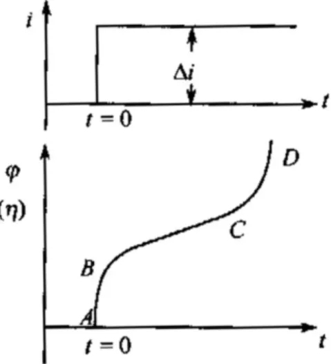
Fig. 3 GCD curve of an electrode under a certain current density
When a single step current is applied on WE, the relationship of potential and time is presented in Fig. 3. The reasons caused electric potential variation can be explained as follows:
AB: the moment of current step, the potential abruptly changes, which is caused by the ohmic resistance. Therefore, the electrical double layer near the surface of electrodes can be seemed as equivalent capacitance. As a result, the potential of electrode has not changed. The potential drop accompanies with the current step (10-12s). The potential drop of the ohm (ohmic polarization) has following features.
24
electrode surface is charged. Hence, the subtle change of potential at the initial stage can be attributed to electrochemical polarization. As the electrochemical process proceeds, the reactants are consumed. Consequently, concentration polarization emerges and is established. The change of potential at the last stage is caused by concentration polarization. Whether electrochemical polarization or concentration polarization, they have following property. In other word, the polarization sequence is ohmic polarization, electrochemical polarization and concentration polarization according to the time.
CD: when the reactants are totally exhausted, the double layer is charged again because of the limited diffusion rate of reactants from the bulk. It indicates the reaction is controlled by concentration polarization.
2.3.4 Electrochemical impedance Spectroscopy (EIS)
A low amplitude (≤ 10 mV) is employed as disturbing signal to obtain a linear impedance spectroscopy in a wide range. The research method is called AC Impedance or EIS. EIS is a transient state technique[4]. Here, the conclusions about EIS are directly given without derivation.
25
Fig. 5 Nyquist profiles under controlled by charge transfer and diffusion The other images, for example, Bode profile will be discussed in Chapter 3.
26
Reference
[1] Electrochemical testing technology, Yonghui Liu. [2] Electrochemical measurements, Anli Hu.
[3] Basic electrochemistry and measurement, Hetong Guo, Suwei Yao. [4] An introduction to electrochemical impedance spectroscopy, Chunan Cao, Jianqing Zhang.
27
Chapter 3 The growth mechanism of NiCo
2S
4and the
electrochemical performance in supercapacitors
3.1 Introduction
The rapid development of global economy inevitably brings some issues such as air pollution, the depletion of fossil fuels[1-4]. Therefore, a kind of efficient and sustainable sources of energy is essential. For now, some conversion storage systems are extensively studied and even used in practical applications in many fields, such as Lithium batteries, fuel cells and electrochemical supercapacitors (ESCs). Recently, ESCs have been attracting considerable attention due to their long-term stability, fast charge rate, friendly to the environment and safety[5-6]. Remarkably, they fill the gap between batteries and traditional capacitors, therefore, they could have a high power density and energy density simultaneously[7-8]. Given the benignity to the environment and cost, ESCs are optimum choice, which can be employed as auxiliary power supply to batteries. Consequently, many governments and enterprises have poured human and material resources into this field to explore, research and develop ESCs technologies. The energy in supercapacitors can be stored either by double layer capacitors (EDLCs) or pseudo-capacitors. As the name suggests, the capacitance in EDLCs is associated with an electrode-potential-dependent accumulation of electrostatic charge at the interface. In generally, the carbon with high specific areas and suitable pore size distribution are usually used as electrode materials for EDLCs, such as active carbon, carbon nanotubes and so on. However, they have a limited specific capacity because of its physical mechanism. While pseudo-capacitors, storing energy by a faradaic reaction between the active material and electrolyte, could provide a much higher capacitance than the EDLCs[9]. Transitional metal oxides/sulphides and conducting polymers having a faradaic behavior during the charge storage process, are used as electrode materials for pseudo-capacitors[10-13]. Unfortunately, the irreversible volume change occurring during the intercalating/de-intercalating process often leads to the poor stability and fading electrochemical performance, and then
28
compromise them as electrode materials[5,9-10,14]. Metal-based materials can provide higher capacitance than carbonaceous materials and better stability than conducting polymers. Apart from electrostatic force, they also exhibit electrochemical faradaic reactions in an appropriate potential window. MnO2, NiOx, CoOy, VOz have two or
more oxidation states, therefore often used as electrode materials. But, their intrinsic conductivity is poor, limiting the power density and reducing the cycling performance. In order to achieve much higher power and energy densities at the same time, electrode materials having a high electronic conductivity are necessary.
Recently, transitional metal sulfides have been widely used as electrode materials due to their better conductivity and higher specific capacitance. Particularly, nickel sulfides and cobalt sulfides are frequently employed for supercapacitors[15-19]. It is noted that NiCo2S4 has a much higher conductivity and significant redox properties
than the corresponding component sulfides[20-21]. So far, various NiCo2S4 with
different morphologies, such as a nanosheet, nanotube and nanosphere, have been reported[15,22-25]. NiCo2S4 nanotube arrays aligned on carbon fiber paper was
prepared for supercapacitor electrodes, which showed 1 F cm-2 at current density of 4
mA cm-2[26]. Lemu Girma Beka obtained cockscomb flower-like NiCo
2S4, and it
manifested a maximum capacitance of 4.1 F cm-2[27].
It is known that the redox process reacts on an active material surface or near-surface, therefore the nanostructured materials possess an effective surface and shorter diffusion distance, leading to a better electrochemical performance[28]. Meanwhile, it can retain the original structure under long-time and high loading current conditions.
Inspired by the above considerations, we designed and synthesized NiCo2S4 with
different morphologies by a modified hydrothermal way with an anion-ion exchange. The details are shown as follows.
3.2 Experimental
29
All the reagents of analytical grade were used without further purification.
Before beginning, the Ni foam was cut into two pieces. Furthermore, a slice of Ni foam is used as a “base” for fixing Ni foam. Firstly, the cut Ni foam was washed by acetone to remove the organic substance. Then, they were placed in 0.1 M HCl for 30 min to remove the NiO layer under sonication. Next, they were washed by ethanol and deionized water (DI) in sequence for 15 min with the assistance of sonication. Finally, they were vacuumed at 60 ℃ for the next step.
3.2.2 Preparation of NiCo
2S
4with different morphologies
NiCo2S4 was in situ grown on Ni foam by two steps. Firstly, the precursor was
obtained after hydrothermal method. Lastly, NiCo2S4 can be prepared after the anion
exchange process.
Synthesis of NiCo2S4 precursor: in a typical process, 4 mmol CoCl2·6H2O and 2
mmol CoCl2·6H2O were dissolved into 80 mL DI. After magnetically stirred for 30
min, the solution became pink. Then, a calculated NH4F was added. Next, 24 mmol
urea was put into the pink solution, which had been magnetically stirred for 10 min. Finally, the mixed solution was transferred into a 100 mL Teflon-lined stainless steel autoclave (TLSSA) containing the pre-treated Ni foam and heated at 100 ℃ for 5 h. After cooled to room temperature, the Ni foam was washed by ethanol and water in turn for several times. It can be observed that the Ni foam was covered by pink materials, which is the NiCo2S4 precursor.
The anion-exchange process: after 0.3902 g Na2S was totally dissolved in 60 mL
DI, the solution was sealed in the TLSSA loaded the Ni foams with NiCo2S4 precursor.
The TLSSA was maintained at 160 ℃ for 12 h. When it cooled to ambient temperature, the sample was washed and dried at 60 ℃ in a vacuum oven.
NiCo2S4 with different morphologies were synthesized under the same condition,
apart from the different amounts of NH4F. The as-prepared samples were indexed,
which was discussed in the results and discussion in detail.
30
The crystal structure and composition of the as-fabricated samples were recorded from 10°to 80°at a scanning rate of 5°/min by XRD (REGAKU). The chemical state was tested by XPS (KRATOS). The morphology was characterized by FESEM (HITACHI). The high-resolution TEM images were tested by JEM-F200 operated at 200 kV.
3.2.4 Electrochemical measurements
The electrochemical performance was tested in a traditional 3-electrode system in 3 M KOH. An Hg/HgO and a piece of platinum net (2×2 cm2) were used as
reference and counter electrodes, severally. As for the working electrode, NiCo2S4/Ni
was cut into 1×1 cm2. Prior to the testing, the sample was soaked in electrolyte and
vacuumed for 30 min. It is believed that it can improve the wettability, which is beneficial to the charge transfer. Cyclic voltammograms (CV) were tested in a potential window of 0-0.65 V under different scanning rates by Solartron 1287 and 1255 B electrochemical station. Galvanostatic charge-discharge curves (GCD) were recorded at various current densities in a fixed potential window of 0-0.55 V. Electrochemical impedance spectroscopy (EIS) was characterized from 106-10-2 Hz at
an amplitude of 10 mV. The specific capacitance was calculated from the discharge curves according to equation:
C = △t×I
where △t stands for the discharge time (s); I is the current density (mA cm-2).
3.3 Results and discussions
Fig. 1 The placement and size of Ni foam and its image after hydrothermal reaction It should point out that the Ni foam was fixed on the base, no matter in
31
hydrothermal reaction or anion-exchange process. Under the condition, the Ni foam can keep still during the whole process, which is very important to prepare NiCo2S4
with appointed morphology. Unlike the other reports, the NiCo2S4 precursor was
grown on the back side rather than the front side, as shown in Fig. 1.
Fig. 2 Schematic illustration of the synthesis route towards NiCo2S4
The typical synthesis of NiCo2S4 on Ni foam was illustrated in Fig. 2. Firstly,
anions of CO32-and OH- were released from urea when the TLSSA was subjected to
hydrothermal reaction[15,29]. Then, Ni2+ and Co2+ reacted with anions, forming into
the pink Ni-Co carbonate hydroxide precursor. Finally, NiCo2S4 can be obtained from
the precursor after anion-exchange process[15].
NiCo2S4 with different morphologies were prepared and their morphologies were
recorded by FESEM and TEM. For convenience, they were named as NC-1, NC-2, NC-3 and NC-4.
3.3.1 Characterization of morphology
NiCo2S4 with four different morphologies were in situ grown on Ni foam for
supercapacitors. For comparison, the morphology of pretreated Ni foams was firstly characterized by FESEM, which was shown in Fig. 3. From Fig. 3a, b, it can be
32
observed that Ni foam has 3-D spongy-like structure. Namely, Ni foam can provide much active sites for in situ growing NiCo2S4. Furthermore, the original surface of Ni
foam is very smooth, which is very different from those of Ni foams after hydrothermal method.
Fig. 3 FESEM of Ni foam
Fig. 4 FESEM of NC-1
The low magnification (Fig. 4 a, b) presented that the original smooth Ni foam is uniformly covered by a highly well-defined honeycomb structure in a large scale. From the high resolution FESEM images, Fig. 6c, d, it can be observed that the NC-1 is indeed composed of countless interconnected honeycomb holes and the diameter of the honeycomb is about 100-200 nm, which can be seemed as “reservoir” of
33
electrolyte for high kinetics. In order to get insight into the structure, TEM was further employed and the results were shown in Fig. 5.
Fig. 5 TEM of NC-1
Fig. exhibited TEM of NC-1. The low magnification of Fig. 5a, b illustrate NC-1 has network-like structure and it is much obvious in Fig. 5c. The highly well-developed 3-D honeycomb structure not only provides much more electroactive sites for the faradaic process, but also effectively shortens the distance of the charge transfer and ion diffusion to the active material surface[30]. Furthermore, NC-1 grew in situ on the conductive Ni substrate surface, therefore, the 3-D materials can accommodate relatively high stress and volume change. When employed as an integrated electrode, it could show a high specific capacitance and long stability. As a comparison, needle-like, flake-like, and petal-like NiCo2S4 materials, indexed as
NC-2, NC-3 and NC-4 on Ni foam have also been prepared. The FESEM and TEM of NC-2 were presented as follows.
Fig. 6 FESEM of NC-2
34
array in a large scale, like a weed. Furthermore, the NiCo2S4 needles did not
agglomerate together, which is favored by electrochemical reaction. However, NC-2 did not have inter-crossed porous structure, which differs from the NC-1. In order to confirm the details of NC-2, cross-section FESEM of NC-2 was also tested.
Fig. 7 cross-section FESEM of NC-2
Firstly, NC-2 underwent ultrasonic processing for 30 min to obtain the needle array of NC-2 without Ni substrate. From Fig. 7a-c, NC-2 consisted of two parts, needle-like and flake like NiCo2S4. It can be observed that countless inclined NiCo2S4
needles tightly attached the thin NiCo2S4 flake. The gap among the needles could
participate in the electrochemical reaction, and the involved ions can be effectively transferred via the needle to the Ni substrate.
Fig. 8 TEM of NC-2
Fig. 8 was the TEM images of NC-2. The needle-array can be obviously observed in Fig. 8a, b. The needle feature was proven in Fig. 8c. The diameter is about 50 nm, which is an ideal “substrate” for in situ growing other active materials.
35
Fig. 9 FESEM of NC-3
Different from the original Ni foam, NC-3 was uniformly composed of a lot of flakes. Moreover, the flakes were vertically grown on the surface of Ni substrate. At the high resolution Fig. 9e, f, the flakes randomly intersected, forming a large number of small cubes with different shapes, which can be treated as reservoir for the electrochemical reaction.
Fig. 10 TEM of NC-3
NC-3 was also characterized by TEM. The flake feature was further affirmed. From the TEM, we can see that there are a lot of threads, which can be indexed to the flakes. In addition, the different cubes were also observed.
Fig. 11 FESEM of NC-4
36
the morphology is dominated by petal-like NiCo2S4, which is similar to the NC-3. The
electrochemical performance of four samples was tested and the results were supplemented in the next section.
3.3.2 Characterization of chemical composition
Fig. 12 XRD patterns of NC-1, NC-2, NC-3 and NC-4
Fig. 13 Local magnified XRD patterns near (111) and (220) peaks
The XRD patterns of NC-1, NC-2, NC-3 and NC-4 are shown in the Fig. 12. The strong diffraction peaks can be readily indexed to the (311), (400), (511) and (440) planes of the cubic NiCo2S4 phase[30]. The peaks located at about 16° and 27° are
corresponding to the planes of (111) and (22)). In addition, the other of 3 remarkable peaks around 44.5°, 52.0° and 76.6° should belong to the Ni foam. As a result, XRD
37
pattern demonstrated that NiCo2S4 was successfully synthesized. In order to further
evaluate the chemical composition, XPS was employed with respect to NC-1. Details were shown in Fig. 14.
Fig. 14 XPS spectra of NC-1 (a) wide survey, (b) Ni 2p, (c) Co 2p and S 2p The full range pattern in the Fig. 16a indicated that NC-1 is composed of Ni, Co and S elements. The C peak is due to the carbon tape[31]. The Ni 2p high-resolution spectra could be fitted with two spin-orbit doublets of Ni2+ and Ni3+ and two
corresponding shake-up satellites. The binding energy difference of Ni 2p3/2 and Ni
2p1/2 is 20.0 eV, indicating the co-existence of di/tri-valent state. Likewise, in the Co 2p
spectra, the strong peaks demonstrate Co2+ and Co3+ co-existing in the NC-1.
According to the S 2p analysis, the strong peaks can be attributed to S2-[25,29,32]. The
XPS results are consistent with the XRD pattern.
3.3.3 Schematic illustration of mechanism
Just as mentioned in the last section, honeycomb like NC-1, needle-like NC-2, flake-like NC-3, and petal-like NC-4 NiCo2S4 were synthesized by the same method,
38
Fig. 15 possible mechanism for NiCo2S4 with different morphologies
It is apparent that NH4F plays a vital role to synthesize these sorts of morphologies
in our experiment. Just as depicted in the Fig. 15, a conclusion about the growth mechanism can be made as follows; when the amount of NH4F was very limited, the
surface of Ni foam can be activated into effective sites for crystal nucleus growth, and the nucleus just grew up along 1-D direction. As the amount of NH4F was increased, the
partial needle surface was also activated into the active sites, the nucleus grew up along 2-D direction and finally became into flakes. When the amount of NH4F was
sequentially increased, the flake became shorter. While the amount of NH4F reached to
a certain level, all the needle surface was activated into the active sites, the nucleus grew up along 3-D direction. The redundant F- would etch and shuttle through the bulk
materials and finally NC-1 was obtained. Equally important consideration is that the Ni substrate and the base should be tightly fixed in TLSSA. Therefore the substrate can keep still even under harsh conditions, which is very important to prepare NiCo2S4 with
uniform morphologies.
In order to testify the hypothesized mechanism, a series of new attempt has been done to obtain the transitional state between needle and flake. When the morphology is predominated by needle arrays instead of flake, they were named as needle-flake like
![Table 5 Summary on the carbon materials and their electrochemical performances[1]](https://thumb-ap.123doks.com/thumbv2/123deta/8490024.921522/17.892.133.764.220.1059/table-summary-carbon-materials-electrochemical-performances.webp)