西 南 交 通 大 学 学 报
第 55 卷 第 1 期
2020年 2 月
JOURNAL OF SOUTHWEST JIAOTONG UNIVERSITY
Vol. 55 No. 1
Feb. 2020
ISSN: 0258-2724 DOI:10.35741/issn.0258-2724.55.1.34
Research articleEarth Sciences
G
EOTECHNICAL
A
NALYSIS OF
T
EEB
W
EIR
F
OUNDATION
S
OIL
S
TABILITY
A
GAINST
S
EEPAGE
E
FFECTS
堰基土抗渗效应的岩土工程分析
Riaed Saee Jasim Al-SaediCivil Department, Engineering College, Misan University Al-Bnok, Baghdad, Iraq, [email protected], [email protected]
Abstract
The steady state seepage analysis is used to compute the factor of safety against piping for Teeb weir in the eastern part of Maysn. Teeb weir is a one of a swarm of hydraulic structures that were suggested and designed to reduce flooding risk in the Teeb area, and to work as a water harvesting system to recharge ground water in the area. The geotechnical engineering map is drawn to analysis the soil properties and estimate the suitability of the soil to support foundation of the weir body and downstream reservoir. SEEP/W software is used to solve the water seepage model underneath the weir foundation. Only the saturated model is selected to compute the factor of safety against vertical piping and to denote the zone of potential piping erosion. The model results show that the stability is critical and that there is a high possibility of failure expected, especially in the downstream zone.
Keywords:Factor of Safety, Liquification Zone, Finite Element, Total Head, Pore Water Pressure
摘要 稳态渗流分析用于计算梅森东部特布堰的管道安全系数。特布堰是为减少特布地区的洪水风险 而提出并设计的一组水工结构之一,并用作集水系统以补充该地区的地下水。绘制了岩土工程图以分 析土壤特性并评估土壤是否适合支撑堰体和下游水库的地基。渗透/W软件用于求解堰基础下方的渗 水模型。仅选择饱和模型来计算垂直管道的安全系数并表示潜在管道腐蚀的区域。模型结果表明,稳 定性至关重要,并且预期发生故障的可能性很高,尤其是在下游区域。 关键词: 安全系数,液化区,有限元,总压头,孔隙水压力
Climate changes increased the drought and water crisis in arid and semi-arid areas, resulting in a need for new facilities to control and benefit from water resources in these areas [2]. Weir is an overflow structure that stretches across an open channel of water, alters the channel’s flow characteristics, and blocks the flow of water, causing it to pool behind it until it is deep enough to flow over the top of the weir [13]. The velocity and flux of the seep water underneath the weir foundations, uplift pressure, and piping erosion resulting from this seep represent the most serious problems in weir stability [10]. The numerical approaches are developed to study the stability of the weir by many researchers, and many types of software were developed to simulate the soil conditions. The Geo-studio software by the GEOSLOPE company is a package of geo-engineering software developed to deal with different geotechnical problems. One of these pieces of software is SEEP/W. According to GEOSLOPE International, "SEEP/W is a finite element CAD software product for analyzing groundwater seepage and excess pore-water pressure dissipation problems within porous materials such as soil and rock".
Its comprehensive formulation allows one to consider analyses ranging from simple, saturated steady state problems to sophisticated, saturated/unsaturated time-dependant programs. SEEP/W is a useful tool that uses numerical modeling to solve complex groundwater seepage problems [5], [6], [7], [8].
The steady state case used in this study was used to analysis the stability of the proposed Teeb weir. In this type of analysis, the water pressure and water flow rates do not change with time. When developing a numerical steady-state model using SEEP/W, the geometry, material properties, and boundary conditions must be assumed [3], [6].
A. The Study Problem
In order to propose a method of protecting the stability of soil underneath the weir foundation against seepage piping, the study performed the following steps:
a. Using SEEP/W 2012 software to compute the factor of safety for the piping.
b. Estimating the stability foundation against liquefaction by studying the pore water pressure distribution model.
foundation.
B. Teeb Weir Location
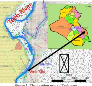
Teeb weir is located to the northeast of Amara city at Universal Transverse Mercator (UTM) coordinates of 38 S 702085 m E and 3582581 m N, Figure 1. Its distance from the Iraqi-Iranian border is about 23 km.
Figure 1. The location map of Teeb weir
C. Geotechnical Soil Properties
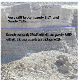
Geologically, Teeb is located in an area of wavy, low hills of about 50 m above sea level. The area is covered with detrital deposits of alluvial and aeolian origin, (Figure 2). These deposits results from the erosion of quaternary and tertiary formations to the northeast of the Zagros Mountains Mountains [1]. The construction material quarriespresent near the weir site (Figure 3) shows the soil succession clearly. Missan engineering bureau was instrumental in completing the geotechnical investigation of the weir site [11]. Eight boreholes were driven along proposed weir axis to a depth of 25m below ground level. The soil succession comprised of two soil layers as following:
a. Upper layer: very stiff, brown sandy silt and sandy clay. This layer extends to a depth of 1- 1.5 meters below ground surface;
b. Lower layer: dense, brown sandy gravel with silt and gravelly sand, this layer extends to a depth of 24 m.
Figure 2. The surface map of the soils in the area
Figure 3. The soil succession in quarry outcrop near weir location
D. River Teeb Hydrology
River Teeb flows from the Zagros Mountains, Iran, crosses borders of Irag and enters the northeasternpart of the Maysan province. The length of the river from the source to the estuary is about 165 km with a basin area of 3637 km2. The slope of the river course is about 50 cm/km.
The hydrological properties are measured [11] in four stations along the river course (Table 1).
Table 1.
Hydrological properties of River Teeb [11]
No Metering station site UTM coordinates (m) Cross- sectional area m2 Flow rate m3 /sec Dischar ge m3 /sec Distance from Iranian borders (km) E N 1 Teeb station bridge 704405 3590062 950 1.5 1425 2 2 Syed Youssef Bridge 703179 3573888 910 1 910 19 3 Engineering bridge e 705406 3565328 900 1 900 26 4 AL-Shuwaikh Bridge 712085 3249402 800 1 800 35
II. METHODOLOGY
The downstream toe is the most critical area under any weir structure as it is where blowouts, piping, and excessive seepage can occur. Seepage analyses are often conducted to evaluate the stability of such areas by computing the factor of safety for the potential piping. SEEP/W, a numerical modeling tool, does not automatically
compute factor of safety against piping but it does provide seepage gradients at nodes within the finite element mesh which provides the information required for computing factors of safety against piping [6], [9], [12]. To simulate and solve the problem of seepage underneath Teeb weir, a model of the weir is constructed by conducting the subsequent procedures.
A. Geometry
The design of Teeb weir was achieved by the Engineering Designs Directory, Ministry of Water Resources [4]. The designs were used to draw the weir cross section (Figure 4). The crest has 6.5m height above ground level and a width of 6.5m. The weir upstream cutoff wall has a depth of 5.9 m below ground level. The cutoff was suggested to reduce water seepage pressure and seepage velocity of the soil underneath the weir foundation. The thickness of the cutoff wall is 0.75 m.
Figure 4. The cross section of Teeb weir
B. Meshing
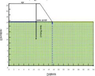
The finite element model of quads and tringle mesh pattern is used to simulate the study problem. The approximate global element size is 5m, and the constructed mesh has 2232 nodes and 2132 elements (Figure 5).
Figure 5. Finite element mesh and geometrical elements of Teeb weir
C. Material Properties
Three materials properties options are available in SEEP/W:
analysis remains saturated during model running;
b.
Saturated/unsaturated – used when unsaturated zone is expected;c.
Interface – used when hydraulic conductivity is zero.In the steady-state Teeb weir model, the saturated-only materials properties are selected to represent soil region, with hydraulic conductivity equal to 0.001 m/sec, while the horizontal to vertical effective hydraulic conductivity ratio is equal to one (Ky’/Kx’ = 1). The interface material is used to signify the cutoff wall.
D. Boundary Conditions
The head boundary conditions are used in the study model because there is free water present in the model. In this type of boundary condition, water elevations in both upstream and downstream models are used.
III.
RESULTS ANALYSISThe seepage analysis is conducted for the two main applications: calculating the flow rate through soil and finding the hydraulic gradient to determine the factor of safety against piping. In this study, the flow rates and vertical gradient in the downstream side of the weir are computed. The model results of total head, pressure head and pore water pressure underneath dam are shown in Figures 6, 7 and 8 respectively. This figure appears to show high water seepage in the soil and excess water pressure in the downstream weir toe, that leads to an increase in the downstream vertical gradient (toe) (Figures 9 and 10). The granular soil tends to fail and is eroded when the pore water pressure exceeds or equals the vertical stress. The zone of potential liquification and piping erosion underneath Teeb weir is shown in Figure 11.
A. Factor of Safety
SEEP/W has no automatic way to compute the factor of safety against piping. The seepage gradients at nodes within the finite element mesh (at the downstream toe). Equation 1 is used to compute the factor of safety against vertical seepage exits [3]:
FSexit = (ᵞsub/i.ᵞw) (1) where ᵞsub is the submerged unit weight of the weir foundation soil; ᵞw is the unit weight of water; and i is the y or vertical hydraulic gradient.
According to the above equation, the factor of safety against seepage piping erosion is equal to 1.3.
Figure 6. The total head model
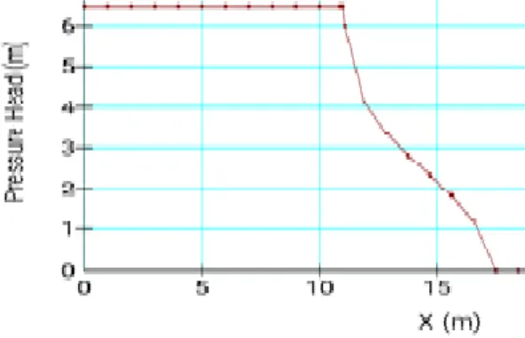
Figure 7. Pressure head model
Figure 8. Pore water pressure
Figure 9. The vertical gradient underneath weir foundation
Figure 10. The pressure distribution underneath weir foundation
Figure 11. The zone of potential liquification and piping erosion
IV. CONCLUSIONS
The Teeb weir is located on a granular, high erodibility and high hydraulic conductivity site. The geological engineering map shows that the weir area is covered with alluvial and colluvial deposits. This material represents a good material for constructing filters and a concrete weir body. The geotechnical investigation and borehole logs appear to show that the weir foundations will be supported by granular, high hydraulic conductivity, erodible soil. The SEEP/W model explains the behavior of the weir foundation. It is obvious that the project needs more procedures to increase the factor of safety to more than 1.3. These procedures include a slurry trench to the upstream side, a weighting berm to the downstream side and a grouting zone below the weir body.