Easily Testable Sequential Machines with Extra Inputs
FUJIWARA, MEMBER, IEEE, NAGAO, TSUTOMU SASAO, MEMBER, IEEE,
KOZO KINOSHITA, MEMBER, IEEE
Abstract-In this paper, an easily testable machine is defined as one which possesses: 1)adistinguishing sequence oflengthIlog2 nI whichforces the machine into a specific state Si, and 2)transfer sequencesof lengthat most[10g2 n]to carry the machinefrom state S1tostateSifor all i. Adesign procedure is presented in whichan arbitrary machine is augmented to an easily testable machine by adding twospecial input symbolstotheoriginalmachine. An efficient procedure is also described for designing checking experiments for the easilytestable machines. For an n-state, m-input symbol ma- chine, thisprocedure gives abound on thelength of the checking experiment that isapproximately mn[og,n].Furthermore, the total checking experiments arepreset.
Index Terms-Checking experiments, distinguishing sequences, easily testablemachines,fault detection, sequential machines,shift register,transitionchecking.
I. INTRODUCTION
FOR sequentialmachines several authors [1]-[6]have considered thefault detection problemas anidentifica- tion problem of sequential machines, that is, finding an input-output sequence which describes a given machine uniquely.Anumber of these papers are based on a method given by Hennie [2] fordesigning checking experiments, called the transition checking approach. His methodyields good results for machines that possess a
distinguishing
sequence, and for machines that are reduced, strongly connected, and such that the actualmachinehas nomore states than the correctly operating machine. However, for machines which do not have anydistinguishing
se- quences, Hennie's procedure yields very long experi- ments, which makes it impractical. Therefore, several methods have been proposed for modifying a given se- quential machine into a new one for which a short check- ing experiment can easily be found [3], [7]-[13]. These include: 1) a method of adding extra outputs [7], [8], and2) amethod ofadding
extrainputs [9]-[11].
Foran n-statem-input symbol machine,the formergivesabound on thelength
ofchecking experiments
that is approxi- matelymn3,
and the lattergives
abound ofmn2.This paperdescribesamethod to augment anarbitrary machine to an
easily
testable machine byadding
two specialinput
symbols, andgives
an efficient procedure to construct achecking experiment
for it. For an n-state, m-input symbol machine, this proceduregives
a good bound on the length of checkingexperiments
that is ap- ManuscriptreceivedFebruary13,1974; revised January 17, 1975. H.Fujiwara,T.Sasao,andK.Kinoshitaarewith theDepartment ofElectronic Engineering, Osaka University,Osaka, Japan.Y. Nagao is with the Technical Laboratory, Kawasaki Heavy Industries, Ltd., Hyogo, Japan.
proximately mn[log2 n], where the square brackets denote
"the smallest integer greater than or equal to the num- ber inside the brackets." Furthermore, the total checking experimentis presetand thus requires noadaptiveinitializ- ing sequence that adaptively brings the machine under test tothestartingstate.
II. NOTATION AND BASIC DEFINITIONS The sequential machines considered in this paper are assumed to befinitestate,synchronous, anddeterministic Mealy machines, and are not required to be reduced, strongly connected, orcompletely specified. The machine M will be represented by a quintuple M =
(S,I,O,A,X)
where S =
{Sl,S2,-- ,SnI
is a finite set of states, I = {II2,- JImw
is a finite set of input symbols, 0 = {01,02,. . .
,01I
is a finite set ofoutput symbols,
B: S X I--+ S is called the nextstatefunction,
and X: S X I -+0 is called the outputfunction.A checking experiment is an input-output sequence which when theinputsequence isapplied tothe testedmachine, an output sequence isproducedwhich establisheswhether or not the tested machine is equivalent to the correctly operating machine, subject to somefaultassumptions.
An experimentis said to be adaptive or preset depending on whether the next input signal to apply is or is not based upon the output signals previously produced by themachine.
A synchronizing sequence for a sequential machine is an input sequence whose application is guaranteed to leave themachineina certain final state, regardless of the par- ticularinitialstateof themachine.
A homing sequence for a sequential machine is an input sequence whose application makes it possible to deter- minethefinal state of the machinebyobserving the cor- responding output sequence that the machine produces. Adistinguishing sequence is aninput sequence whose ap- plication makes it possible to determine the initial state of the machine by observing the corresponding output sequence that the machine produces. A transfer sequence from state Si to state
Si
is an input sequence which trans- fersthemachinefrom stateSi
tostateSi.
A machine M' =
(S',I',0',5',X')
is a submachine of the machine M =(S,I,O,6,X)
if and only if S' CSJI'
C I,O'
C0,5'
= a restricted toS'
X I', and ' = X re- strictedtoS'
X I'.An easily testable machine is one for which a short preset
checking
experiment can be found with asimple
algorithm.
Inorderto obtain a short presetchecking
ex- periment,it
is desirable for the machine to have a shortdistinguishing
sequence, a shortsynchronizing
sequence,and short transfer sequences. Therefore, we make the followingdefinition. Aneasilytestable machine is areduced and strongly connected machine which possesses 1) a distinguishing sequence Xd of length [0g2
n]
which forces the machine into aspecific final state Si, i.e., Xdis also a synchronizing sequence, and 2) transfer sequences T(i) withalengththat is at most [10g2n] to movethe machirne fromstate Sito state Sifor alli,where n is the number of states of the machine and whereEx]
denotes the smallest integer greater than orequalto x.Example: Consider the p-stage binary shift register shown in Fig. 1. The p-stage binary shift register is a serial connection of p-unit delays interconnected so that at the occurrence of a shift signal the contents of theith delayisshifted into the (i+ 1)st delay. Let Y1,Y2, .
*,Y,
be thestatevariables, let X be theinputvariable,
andlet Z be the output variable. For the p-stage binary shiftregister,
a p-tuple state assignment Y1Y2...Y,
can be foundfor eachstate such that1) Yi(t + 1) =
Yi_i(t),
i = 2,3,.-. p 2) Y1(t + 1) = X(t)and
3) Z(t) =
Yp(t)
where
Y1(t),Y2(t),..
,Yp(t), X(t), and Z(t) are the val-ues of Y1,Y2,...,
Yp,X,Z
at time t, respectively. Then it is easily seenthat any input sequence of length pwill beboth a distinguishing sequence and a synchronizing se- quence, and that
Ypyp-1...
Y1 is a transfer sequence of length p which carries the p-stage binary shift register to state Si with state assignment Y1Y2 *.Yp.
Therefore, the p-stage binary shift register is an easily testablemachine.
III. AUGMENTATION OF THE GIVEN MACHINE
In this section we present a procedure to augment a
givenmachinebyaddingtwoextrainput symbols sothat theaugmented machine isan easily testable machine.
Inthenextsection wewilldiscuss thedesignofefficient checking experiments under the assumption that faults do not increase the number of states. For a machine realized by binary devices, the probability of the occur- rence of faults that can increase the number of states is indeed rather small when the number of states n is an
integral power of 2, since physical creation of new state variables would have been implied. However, when n is not an integral power of 2, and/or more than [10g2 n] state variables are used in the realization, such faults are
very likely to occur. From this point of view, it is desir- able to augment the original n-state machine so that the augmented machine has2P = n'stateswherep = [log2n].
Let M = (S,I,0,5,X) be a given machine, where S =
IS,S2, * ,Sn}, I = { I1,I2,
jIm}
and 0 = {01,02,...**, Then we can give a procedure for augmenting the givenINPUT OUTPUT
Fig. 1. The p-stage binary shift register.
machine M so that the augmented machine M* is easily testable.
Augmentation Procedure
1) Add new states Sn+l1Sn+2. ,SnI to M if n is not an integral power of 2, where n' - 2P and p =
[log2 n].
2) Assign a p-bit binary code to all states such that eachstate has onlyoneassignment.
3) Add new input symbols
Eo,Ej
to M. The next state function a and the output function X for the new input symbolseo,El
are defined as follows.For each state
Si,
with state assignment Y1Y22..Y,
6
(S&co)
= Sj, and5(Si,s1)
=Sk;
X(Si,fo) = X (Si,E) = 01, if
Yp
= 0=02, if Yp = 1
where
Sj
and Skhavestateassignments0Y1Y2...YP-
and 1YlY2...
Yp-1,
respectively.The effect of this state transition is to shift the state assignmentonedigitto theright and introducea zeroora one as new left most digit according to input so or el,
respectively. Thus, this 2-column submachine restricted to inputs Eo,E1 is isomorphic to the p-stage binary shift register. Since the p-stagebinaryshift registeris an easily testable machine, this 2-column submachine is also easily testable, and hence the augmented machine M* is too. Indeed, in the augmented machine M* obtained above, any input sequence of length p =
[log2
n] consisting of eo and E, isboth a distinguishing sequence and a synchro- nizing sequence, andCypEyP_j-
**Ey22Ey1
is a transfer sequence oflength pwhichtransfersM* from an arbitrary state to state Siwith state assignment Y1Y2...Yp.
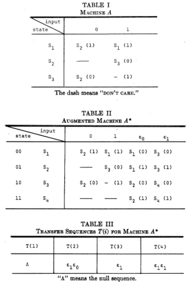
The augmented machine M* has n' states and (m + 2) input symbols, where log2 n' = [log2n].Example: Consider machine A given by Table I. Ma- chine A is not strongly connected and does not have a distinguishingsequence. Byapplyingtheaboveprocedure, we obtain the augmented machine A* shown in Table II. A* has a distinguishing sequence EoEo which is also a syn- chronizing sequence whose final state is Si. Transfer sequences are shown in Table III. Hence the augmented machine A*is aneasily testable machine.
IV. CHECKING EXPERIMENTS FOR THE EASILY TESTABLE MACHINES
In this section we consider checking experiments for the easily testable machines. The principle idea of our method is based mainly on those of Hennie
[2]
and Hsieh [5], and we assume that readers are familiar with the principle of those methods. Assume that the class of allowablefailures satisfies thefollowingconditions. 822TABLE I MACHINEA nput
state\~.~ 0 1
S1 s2 (1) S1 (1)
s2 ~ s3 (0)
S3 S2 (0) - (1)
The dashmeans"DONTCARE."
TABLE II AUGMENTED MACHINEA*
state ipt 0 1 eo E
00 S1 S2 (1) S1 (1) SI (0) S3 (0)
01 S2 S3 (0) S1 (1) S3 (1)
10 S3 S2 (0) - (1) 2 (0) S4 (0)
11 S4 s2 (1) S4 (1)
TABLE III
"A"meansthe null sequence.
1) Any failure which occurs is assumed to occur throughout thetest.
2) Failures do notincrease thenumber of states. Let M =
(S,I,O,5,X)
be an n-state m-input easily testable machine. LetXd be aninput
sequence oflength
[log2 n]
which is both adistinguishing
sequence and a synchronizingsequence. LetSi
bethe finalstateresulting
from theapplication
ofXd. The transfer sequence with a length that is atmost[10g2 n]
to move M fromstate Si to stateSi
is denotedby T(i).The checking experiment consists of five parts. The first part of the checking experiment is the initializing part which brings the machine under test to thestarting state
Si
for theexperiment.
This can be doneby
a syn- chronizing sequence Xd. Hence, the first part of the ex- periment ispreset andhas the form:Input: Xd
State: - S1
(1)
Output:
where the dashmeans "DON'T CARE."X
The second part ofthe
checking experiment
carries thecorrectly
operating
machine through all its states, dis- plays all the different responses to Xd, and thus verifies that Xd is a distinguishing sequence. Thus, the second part ofthechecking experiment has theform:Input: State: Output:
Xd
Si Si
zi
(2)
for allstates Siof M,where Zi =
X(Si,Xd).
The third part of the experiment verifies, by using a
distinguished
sequence Xd validated by the second part of theexperiment,
that Xd is a synchronizing sequence used to force thecorrectlyoperatingmachineintostateSi. Thus, thisparthasthe form:Input: State: Output:
Xd Xd
Si Si
SI
Zi Z1
(3) for all states
Si
of M.The fourth part ofthe
checking
experiment verifies that T(i) transfersthecorrectlyoperating machine from stateIEEE 1975
Si
tostateSi.
This canbe donebyusing adistinguishing sequenceXd asfollows:Input: State: Output:
Xd T(i)
_ SI
Xd
Si Si (4)
-
Zli i
zforall states Si,whereZli = X(Si,T(i)).
The fifth part of the checking experiment is to be de- signedto check all thetransitions andhas the form
Input: State: Output:
Xd T(i)
- Si
[log2n] for i = 1,2,..-,n, where X
I
is the length of X. From the organization of the checking experiment, it can be seen that the total length of the checking experi- mentis at mostn
I Xd'I
+E
T(i) + 2I Xd|)
i1 m n
+ ,
(I T(i)
+I Ij I+ XdI)
Ij Si
- Zii
oij
= x(Si,Ij)
forall states
Si
andinputsIj.
Since the distinguishing sequence Xd and the transfer sequence T(i) havebeen validated bythe
previous
parts ofthe checking experiment,Si
is uniquely determined by T(i) andSij
is recognized by Xd. Note that if both .(Si,Ij)
andX(Si,Ij)
areunspecified,
then such atransi- tionfrom state Siunderinput Ij
neednotbe checked.Although the checking experiment is functionally sub- divided into five parts, these parts need not be phys- ically separated from each other. Parts 1-4 can be com- pletelycontained inthefollowing sequences:
Input: State: Output:
Xd T(i)
_ Si
Xd Xd
Si Si Si
-
Zli Ziz1
Xd
Sij =
(Sl,j)
zij
Si (5)
- (2n+ 1)
IXdI
+E
T(i)i=l
+mn(IXdI
+1)
+ mT(i)
i1
< (2n + 1) [log2 n] +
n[og2 n]
+mn(Elog2
n] + 1) +mnElog2
n]- (3n + 1)[log2n] +mn(2[log2n] + 1).
Thus, the upper bound on the length of the checking experimentis
(3n + 1)[og2
nl]
+mn(2[log2
n] + 1). (6) Forlargem and n, thisboundissmaller than thebound forallstates Si.Thus, the total checking experimentis tobe organized from the
subexperinments
(5) and (6). Then wehave the following checking experiment:(n+ [log2n])(1 +mn)
reported by Holborow
[11],
which is the best bound in theprevious methods[7]-E11].
T(l) XdXd T(2) XdXd
- Si Si Si S2 S
T(1)
IlXd T(1) I2Xd ... Xd T(i) I,Xd ... XdSi Si
T(n) ImXd
Si Sn
In this checking experiment, the initializing part is preset, hence the total checking experiment ispreset, and thus iseasytobe appliedtothe tested machine.
Let us derive the bound on the length of the checking experiment. Since the machine M is assumed to be an easily testable machine,
Xd
= [l0g2n]
and T(i) _Example: Let us construct a checking experiment for machine A* given by Table II. Xd = EoEo is both a dis- tinguishingsequence anda synchronizingsequence whose finalstateis S. Transfersequences T(i) from state Si to each state Siare shown in Table III.
The totalcheckingwexperiment is: Input:
State:
Xd
Xd
T(n)
XdXd1Si s71
Si
S1 Si Si Si824
(a)
EoEo
T(l)
co-o C-oEo(c).
T (b) l-
T
(2)
CoEo foeo- S1 SI Si S S2 .81 Si
-- A 00 00
T(3)
(d)
fEOo COCOS3 Si Si
00 1 0 00 0 0 1 00
(f)
(e) I
T(4) co-o
C-oEo T(1) EoEO T(1) 1 coEoTM1 (a') so
eoeoSi
S4Si Si
S1S2Si
S8S8Si
S8S8Si
00 1 1 00 A 1 1
T(1) El E0EO T(2) 1 ooEo
A 1 00 A 0 00
T (C2)T
IT(2)
eo EoEo T(2) El EOEOS1 s1s3 S1 S2S3 Si S2S1 Si S2S3 -S
A 0 01 00 0 01
T(3) 0 Eo o T(3) 1 EoEo
00 1 00
TI
(d')
I-T(3)
co coco00 1 01
T(r
(e')-
T(3) E'l (0Eo
S S3S2 Si S3- Si S3S2 SI S3S4 Si
0 0 10 0 1 --
r (f')
T(4) so foEo T(4) E1 EoEo
S1 S482 Si S4S4 Si.
00 1 10
0 0 10 0 0 1 1
00 1 11
In the above experiment, subexperiments (a)-(f) are equivalent to (a')-(f'), respectively, and thus subexperi- ments (a')-(f') can be deleted. Then we can obtain the
reduced checking experiment asfollows:
procedure of designing checking experiments for such easily testable machines. For an n-state m-input symbol machine, this procedure gives a bound on the length of checking experiments that is approximately mn[log2 n], Input: EoEo T(1) eoeoeOEo T(2) EocO-oEo T(3) EoEOeOEo T(4) Eo:OEOEo
Output: -- A 0000 00 1000 0 0100 00 1100
T(1) OEoeo T(1) lEoEo T(2) lEoEo T(2) EiEoEo T(3) 0Eoeo T(3) lcoeo T(4) ElEoeo
A 110 A 100 00 001 00 101 0 010 0 1-- 00 111.
V. CONCLUSION
In thispaper, wehave consideredamethodto construct easily testable machines and have considered checking experiments for such machines. Ann-state easily testable machine considered in this paper is one which possesses
1) a distinguishing sequence of length [og2n] which
forcesthe machine into a specificstate
Si
and 2) transfer sequencesoflength atmost 10g2n]to carry the machine from stateSi
to state Si for all i. We have shown that ifan original machine is not easily testable, then it can be modified to an easily testable machine by adding two extra input symbols. We have also presented an efficient
whichis smallerthan the best boundmn2 obtainedin the previous methods [7]-[11].Furthermore, the totalcheck- ing experiment ispreset.
ACKNOWLEDGMENT
The authors wishto acknowledge the support and en-
couragement of Prof. H. Ozaki of Osaka University, -Osaka, Japan. The authors also wish to acknowledge the useful comments of Dr. C. R. Kime of the University of
Wisconsin.
REFERENCES
[1] A. Gill, Introduction to the Theory of Finite-State Machines. New York:McGraw-Hill, 1962.
[2] F. C. Hennie, "Fault detecting experiments for sequential
Input: State: Output:
825
circuits," iL Proc. Jth Annu. Symp. Switching Circuit Theory and Lo icalDesign, Princeton,N. J., Nov. 1964, pp. 95-110. [3] C. R. Kime, "A failure detection method for sequential cir-
cuits," Dep. Elec. Eng., Univ. Iowa, Iowa City, Iowa, Tech. Rep. 66-13, 1966.
[4] G.Gonenc, "A method for thedesignof faultdetectionexperi- ments," IEEE Trans. Comput. (Short Notes), vol. C-19, pp. 551-558, June1970.
[5] E. P. Hsieh, "Checkingexperimentsforsequential machines,"
IEEE Trans. Comput., vol. C-20, pp. 1152-1166, Oct. 1971. [6] D. E. Farmer, "Algorithms for designing fault-detection ex-
periments for sequential machines," IEEE Trans. Comput., vol. C-22,pp.159-167, Feb. 1973.
[7] Z. Kohavi and P. Lavailee, "Design of sequential machines with fault-detection capabilities," IEEE Trans.' Electron. Comput., vol. EC-16,pp. 473-484, Aug. 1967.
[81 R.L.Martin, "Thedesign ofdiagnosable sequential machines," in Proc. HawaiiInt.Conf.Syst. Sci., 1968.
[9] S.-I. Murakami, K. Kinoshita, and H. Ozaki, "Sequential machines capable of fault diagnosis," IEEE Trans. Comput., vol. C-19, pp.1079-1085, Nov. 1970.
[10] J. R. Kane and S. S. Yau, "On the design of easily testable sequential machines," inConf.Rec..12thAnnu.Symp. Switching and Automata Theory, pp. 38-42, Oct. 1971.
[11] C. E. Holborow, "An improved bound on thelengthofchecking experimentsforsequential machineswithcountercycles,"IEEE Trans. Comput. (Short Notes), vol. C-21, pp. 597-598, June 1972.
[12] M. J. Y. Williams and J. B. Angell, "Enhancing testabilityof large-scale integrated circuits via test points and additional logic," IEEE Trans. Comput., vol. C-22, pp. 46-60,Jan. 1973. [13] H. Fujiwara and K. Kinoshita, "Design ofdiagnosablesequen- tial machines utilizingextra outputs," IEEE Trans. Comput., vol.C-23, pp. 138-145, Feb. 1974.
~$a~: Hideo Fujiwara (S'70-M'74) was born in
'
lNara, Japan, on February 9, 1946. He re- ceived theB.E., M.E., and Ph.D.degreesin electronic engineering fromOsaka University,>~Osaka, Japan, in 1969, 1971, and 1974, re- spectively.
He iscurrentlyaResearchAssistant inthe
Departmentof ElectronicEngineering,Osaka University.Hisresearchinterestsareswitch- ing theory and automata theory, and he
specializes in the developmentof fault diag- nosis oflogicalcircuits.
Dr.Fujiwara is a member of the Institute of Electronics andCom- munication Engineers of Japan.
Yoich Nagao was born in Hyogo, Japan, on July 17, 1949. He received the B.E. and M.E. degrees in electronic engineering
from Osaka University, Osaka, Japan, in 1972 and1974,respectively.
Since 1974he has been with the Technical
Laboratory, Kawasaki Heavy Industries, Ltd., Hyogo, Japan. His research
interests
are switching theory and automata theory. Mr. Nagao is a member of the Institute of Electronics and Communication Engineers ofJapan.
i' Tsutomu Sasao (S'72) was born in Osaka, Japan, on January 26, 1950. He received theB.E. and M.E. degreesinelectronic engi- neeringfromOsakaUniversity,Osaka, Japan, in1972and 1974, respectively. He is currently aPh.D. student in the Department of Elec- tronic Engineering, Osaka University.
His research interests areswitching theory and automatatheory.
Mr. Sasao is a member of the Institute of Electronics and Communication Engineers of Japan.
IKozo
Kinoshita (S'58-M'64) was born in Osaka, Japan, on June 21, 1936. He re-ceived
theB.E., M.E., and Ph.D. degreesin commnunication engineering fromOsakaUni- versity, Osaka, Japan, in 1959, 1961, and 1964,respectively.Since 1964 he has been with Osaka Uni- versity, where he isnowanAssociate Profes-
sor of Electronic Engineering. His fields of
interest are switching theory, system and logicaldesign, and fault diagnosis of informa- tionprocessingsystems.
Dr.Kinoshitaisamemberof the InstituteofElectronicsandCom- munication Engineers of Japan and the Information Processing SocietyofJapan.