Copyright
© 2005 Proxim Corporation. All rights reserved. Covered by one or more of the following U.S. patents: 5,231,634; 5,875,179; 6,006,090; 5,809,060; 6,075,812; 5,077,753. This user’s guide and the software described in it are copyrighted with all rights reserved. No part of this publication may be reproduced, transmitted, transcribed, stored in a retrieval system, or translated into any language in any form by any means without the written permission of Proxim Corporation.
Trademarks
ORiNOCO is a registered trademark, and Proxim, and the Proxim logo are trademarks of Proxim Corporation. Acrobat Reader is a registered trademark of Adobe Systems Incorporated.
Ekahau is a trademark of Ekahau, Inc.
HyperTerminal is a registered trademark of HilGraeve, Incorporated.
Microsoft and Windows are a registered trademarks of Microsoft Corporation. Netscape is a registered trademark of Netscape Communications Corporation. SolarWinds is a registered trademark of SolarWinds.net.
All other trademarks mentioned herein are the property of their respective owners.
OpenSSL License Note
This product contains software developed by the OpenSSL Project for use in the OpenSSL Toolkit (http://www.openssl.org/) and that is subject to the following copyright and conditions:
Copyright (c) 1998-2002 The OpenSSL Project. All rights reserved.
The names "OpenSSL Toolkit" and "OpenSSL Project" must not be used to refer to, endorse, or promote the products or for any other purpose related to the products without prior written permission. For written permission, please contact [email protected].
This software is provided by the OpenSSL Project “as is” and any expressed or implied warranties, including, but not limited to, the implied warranties of merchantability and fitness for a particular purpose are disclaimed. In no event shall the OpenSSL Project or its contributors be liable for any direct, indirect, incidental, special, exemplary, or consequential damages (including, but not limited to, procurement of substitute goods or services; loss of use, data, or profits; or business interruption) however caused and on any theory of liability, whether in contract, strict liability, or tort (including negligence or otherwise) arising in any way out of the use of this software, even if advised of the possibility of such damage.
ORiNOCO AP-4000 Series User Guide Software v3.1
3
Contents
1
Introduction . . . 9
Products Covered in this User Guide . . . 9
Document Conventions . . . 9
Introduction to Wireless Networking . . . 10
Mesh Networking (AP-4000M/4900M Only) . . . 11
Mesh Network Convergence . . . 11
Mesh Network Configuration . . . 13
Guidelines for Roaming . . . 14
IEEE 802.11 Specifications . . . 15
Management and Monitoring Capabilities . . . 15
HTTP/HTTPS Interface . . . 15
Command Line Interface . . . 15
SNMP Management . . . 16
SSH (Secure Shell) Management . . . 17
2
Installation and Initialization . . . 18
AP-4000 Series Hardware Description . . . 18
Overview. . . 18
Antennas . . . 19
Active Ethernet . . . 20
LED Indicators . . . 21
Prerequisites . . . 22
General Prerequisites. . . 22
Mesh Prerequisites. . . 23
Product Package . . . 24
System Requirements . . . 24
Hardware Installation. . . 25
Required Materials . . . 25
Cabling the AP-4000/4000M/4900M . . . 25
Installing the Security Cover. . . 26
Mounting the AP-4000/4000M/4900M . . . 26
Installing External Antennas . . . 28
Installing the AP in a Plenum . . . 29
Initialization . . . 31
Using ScanTool. . . 31
Logging In. . . 33
Using the Setup Wizard . . . 35
Installing the Software . . . 37
3
System Status . . . 41
4
Advanced Configuration . . . 42
System . . . 44
Dynamic DNS Support . . . 44
Network . . . 46
IP Configuration . . . 46
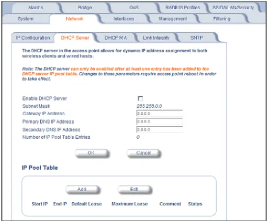
DHCP Server . . . 47
DHCP Relay Agent. . . 49
Link Integrity . . . 50
SNTP (Simple Network Time Protocol) . . . 51
Interfaces. . . 54
Operational Mode . . . 54
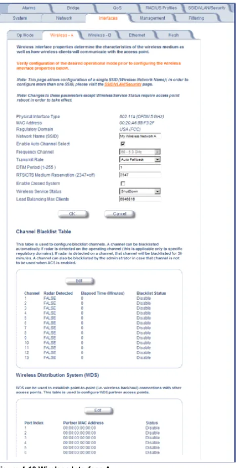
Wireless-A (802.11a Radio) and Wireless-B (802.11b/g Radio). . . 57
Ethernet . . . 64
Mesh (AP-4000M/AP-4900M Only) . . . 66
Management . . . 68
Passwords . . . 68
IP Access Table . . . 69
Services . . . 69
Automatic Configuration (AutoConfig) . . . 75
Hardware Configuration Reset (CHRD) . . . 77
Filtering . . . 80
Ethernet Protocol . . . 80
Static MAC . . . 80
Advanced . . . 83
TCP/UDP Port . . . 83
Alarms . . . 85
Groups . . . 85
Syslog. . . 90
Rogue Scan . . . 93
Bridge . . . 97
Spanning Tree . . . 97
Storm Threshold . . . 98
Intra BSS . . . 99
Packet Forwarding . . . 99
QoS . . . 100
Wireless Multimedia Extensions (WME)/Quality of Service (QoS). . . 100
Priority Mapping . . . 102
Enhanced Distributed Channel Access (EDCA). . . 103
Radius Profiles . . . 106
5
Configuring Radius Profiles . . . 107
MAC Access Control Via RADIUS Authentication . . . 110
802.1x Authentication using RADIUS. . . 110
RADIUS Accounting . . . 110
SSID/VLAN/Security . . . 113
VLAN Overview . . . 113
Management VLAN . . . 115
Security Profile . . . 116
MAC Access . . . 123
Wireless-A or Wireless-B . . . 123
Broadcast SSID and Closed System . . . 128
5
Monitoring . . . 129
Version . . . 130
ICMP . . . 131
IP/ARP Table . . . 131
Learn Table . . . 132
IAPP . . . 132
RADIUS . . . 133
Interfaces. . . 134
Station Statistics . . . 137
Mesh Statistics . . . 138
6
Commands . . . 139
Introduction to File Transfer via TFTP or HTTP . . . 139
TFTP File Transfer Guidelines . . . 140
HTTP File Transfer Guidelines . . . 140
Image Error Checking During File Transfer . . . 140
Update AP . . . 141
Update AP via TFTP. . . 141
Update AP via HTTP . . . 142
Retrieve File . . . 143
Retrieve File via TFTP . . . 143
Retrieve File via HTTP . . . 144
Reboot . . . 146
Reset . . . 146
Help Link . . . 147
7
Troubleshooting . . . 148
Troubleshooting Concepts. . . 148
Connectivity Issues. . . 148
Basic Software Setup and Configuration Problems . . . 149
Client Connection Problems . . . 150
VLAN Operation Issues . . . 151
Active Ethernet (AE) . . . 151
Recovery Procedures . . . 152
Reset to Factory Default Procedure . . . 152
Forced Reload Procedure . . . 152
Setting IP Address using Serial Port . . . 155
Related Applications . . . 156
RADIUS Authentication Server. . . 156
TFTP Server . . . 157
A Command Line Interface (CLI). . . 158
General Notes . . . 158
Prerequisite Skills and Knowledge . . . 158
Notation Conventions . . . 158
Important Terminology . . . 158
Navigation and Special Keys . . . 159
CLI Error Messages . . . 159
Command Line Interface (CLI) Variations . . . 160
Bootloader CLI . . . 160
CLI Command Types. . . 161
Operational CLI Commands . . . 161
Parameter Control Commands. . . 165
Using Tables and Strings. . . 169
Working with Tables . . . 169
Using Strings . . . 169
Configuring the AP using CLI commands . . . 170
Log into the AP using HyperTerminal . . . 170
Log into the AP using Telnet. . . 170
Set Basic Configuration Parameters using CLI Commands . . . 170
Other Network Settings . . . 175
CLI Monitoring Parameters . . . 184
Parameter Tables . . . 184
System Parameters . . . 187
Network Parameters. . . 188
Interface Parameters . . . 191
Management Parameters . . . 197
Filtering Parameters . . . 202
7
Bridge Parameters . . . 206
RADIUS Parameters . . . 208
Security Parameters . . . 209
VLAN/SSID Parameters . . . 211
Other Parameters . . . 211
Wireless Multimedia Enhancements (WME)/Quality of Service (QoS) parameters . . . 211
CLI Batch File . . . 214
Auto Configuration and the CLI Batch File . . . 214
CLI Batch File Format and Syntax . . . 214
Reboot Behavior. . . 215
B ASCII Character Chart . . . 216
C Specifications . . . 217
Software Features . . . 217
Number of Stations per BSS . . . 217
Management Functions . . . 217
Advanced Bridging Functions. . . 218
Medium Access Control (MAC) Functions . . . 218
Security Functions . . . 218
Network Functions . . . 219
Hardware Specifications . . . 220
Physical Specifications . . . 220
Electrical Specifications . . . 220
Environmental Specifications . . . 220
Ethernet Interface . . . 220
Serial Port Interface . . . 220
Active Ethernet Interface . . . 220
Available Channels . . . 221
AP-4000/4000M Channels . . . 221
AP-4900M Channels . . . 222
D Technical Support. . . 224
Online Support . . . 224
Telephone Support . . . 225
E
Statement of Warranty . . . 226
Warranty Coverage . . . 226
Repair or Replacement . . . 226
Limitations of Warranty . . . 226
Support Procedures . . . 226
Other Information . . . 227
Ask a Question or Open an Issue . . . 227
Other Adapter Cards . . . 227
F
Regulatory Compliance . . . 228
Safety Information (USA, Canada, & European Union) . . . 230
Federal Communications Commission (FCC) (AP-4000/4000M) . . . 231
Warnings . . . 232
Caution: Exposure to Radio Frequency Radiation . . . 232
Modifications . . . 232
Industry Canada (IC) (AP-4000/4000M only) . . . 233
European Union (AP-4000/4000M only) . . . 234
Regulatory Compliance Certifications Summary (AP-4000/4000M) . . . 235
9
1
Introduction
This chapter contains information on the following: • Products Covered in this User Guide
• Document Conventions
• Introduction to Wireless Networking • Mesh Networking (AP-4000M/4900M Only) • Guidelines for Roaming
• IEEE 802.11 Specifications
• Management and Monitoring Capabilities
Products Covered in this User Guide
This User Guide details functionality of the AP-4000 Series Access Points, consisting of the following:
Document Conventions
• AP refers to an AP-4000, AP-4000M, or AP-4900M Access Point.
• AP Series refers to the AP-4000, AP-4000M and AP-4900M Access Points.
NOTE:Unless otherwise noted, screen captures in this User Guide are from the AP-4000.
• 802.11 is used to describe features that apply to the 802.11a, 802.11b, and 802.11g wireless standards. • Blue underlined text indicates a link to a topic or Web address. If you are viewing this documentation on your
computer, click the blue text to jump to the linked item.
• Text enclosed within triangle brackets, < >, should be replaced with a user-defined value. • The following special notations are used:
NOTE:A note contains important information that helps you make better use of the AP or your computer.
CAUTION:A Caution indicates potential damage to hardware or loss of data.
WARNING: A Warning indicates imminent danger to hardware or loss of data.
Product Description
AP-4000 Tri-mode AP that supports:
• 802.11b, 802.11g, or 802.11a clients simultaneously
The AP-4000 can be converted to an AP-4000M using Proxim’s Mesh Software Kit. AP-4000M Tri-mode AP that supports:
• 802.11b, 802.11g, or 802.11a clients simultaneously • Mesh networking
AP-49000M Tri-mode AP that supports:
• 802.11b, 802.11g, or 802.11a clients simultaneously • Mesh networking
Introduction to Wireless Networking
Introduction to Wireless Networking
An Access Point extends the capability of an existing Ethernet network to devices on a wireless network. Wireless devices can connect to a single Access Point, or they can move between multiple Access Points located within the same vicinity. As wireless clients move from one coverage cell to another, they maintain network connectivity.
In a typical network environment (see Figure 1-1), the AP functions as a wireless network access point to data and voice networks. An AP network provides:
• Seamless client roaming for both data and voice (VoIP) • Easy installation and operation
• Over-the-air encryption of data • High speed network links
Mesh Networking (AP-4000M/4900M Only)
11
Mesh Networking (AP-4000M/4900M Only)
Using the ORiNOCO Mesh Creation Protocol (OMCP), The AP-4000M and AP-4900M support structured Mesh networking. For information on converting an AP-4000 into an AP-4000M to enable Mesh functionality, see Mesh Software Kit.
In a mesh network, access points use their wireless interface as a backhaul to the rest of the network. Access points connected directly to the wired infrastructure are called “portals;” mesh access points relay packets to other mesh access points to reach the portal, dynamically determining the best route over multiple “hops.”
Mesh networks are self-configuring (a mesh access point will scan for other mesh access points periodically and choose the best path to the portal) and self-healing (the network will reconfigure data paths if an AP or link fails or becomes inactive).
Mesh Network Convergence
Mesh networks are formed when mesh APs on the same channel have the identical Mesh SSIDs, security settings, and management VLAN IDs when VLAN is enabled. As these Mesh APs come online, they discover and set up links with each other to form the Mesh network.
Figure 1-2 Mesh Startup Topology Example – Step 1
In Figure 1-2, MP1 and MP9 are APs configured as Mesh portals, each on a different channel. When they are up and running, they will transmit beacons with a Mesh information element (IE) containing a Mesh SSID, and respond to probe requests that contain Mesh IEs with the same Mesh SSID.
Mesh Networking (AP-4000M/4900M Only)
are discovered, MAP2 through MAP8 will build a neighbor table from the beacons and probe responses they receive. The neighbor table contains three kinds of links:
• Active: Link with a mesh neighbor that has gone through association and authentication, and the port is open. • Connected: Link with a mesh neighbor that has gone through association and authentication, but the port is closed. • Disconnected: Possible link to a mesh neighbor that has not gone through association and authentication.
From the neighbor table, MAP2 through MAP8 will select the best possible connection to the backbone network. This connection is the active link. If a link to the backbone on a different channel is significantly better than any on the current channel, then MAP2 through MAP8 will switch to a new channel and join the Mesh network on that channel.
In Figure 1-2 through Figure 1-4, the circles approximately indicate the range of the respective Mesh radios. As shown in these figures, MAP2 and MAP4 will discover Mesh Portal (MP) 1, and MAP7 and MAP8 will discover MP9. MAP3 is also within reach of MAP2 and MAP4, but they will not allow MAP3 to connect until they have established a Mesh link to the Mesh Portal.
Assume that links are established as shown in Figure 1-3. Solid lines indicate established links.
Figure 1-3 Mesh Startup Topology Example – Step 2
After the first Mesh links are formed, MAP2,4,7 and 8 will add the Mesh IE to their beacon and respond to probe requests with a Mesh IE containing the same Mesh SSID and security settings. Eventually MAP 3 will find both MAP2 and 4 and will setup a Mesh link with the one with the best path to the portal, say MAP2. Optimal paths are chosen based on the number of hops to the portal, RSSI (relative signal strength), and medium (air) utilization.
Mesh Networking (AP-4000M/4900M Only)
13 from MAP4 to MP1 fails, MAP4 can still reach the backbone via MAP3 and MAP2. The same goes for other MAPs that discover each other.
After a short while, the network in this example will look like Figure 1-4, where solid lines indicate active Mesh links and dotted lines indicate established but inactive Mesh links.
Figure 1-4 Mesh Startup Topology Example – Step 3
In this example, if MAP8 loses the Mesh link to MP1, MAP8 will immediately activate the Mesh link to MAP7. If the link to MAP7 has a higher path cost than a possible link to MAP4, which has the same Mesh SSID and security mode but is on a different channel, then MAP7 may decide to switch channels and establish and activate a link to MAP4.
Mesh Network Configuration
In the AP-4000M/4900M, either of the wireless interfaces may be configured for Mesh functionality, with the following considerations in mind:
• To form or join a Mesh network, Mesh APs must have identical Mesh SSIDs and security modes (None or AES). • All Mesh APs within a network must be on the same channel. The channel used by the Mesh portal will determine the
channel used by the entire mesh network.
• Mesh APs must have static IP addresses, as the DHCP client will not function on wireless interfaces.
• On Mesh APs, Mesh and WDS functionality cannot co-exist on the same wireless interface. Mesh and WDS can co-exist on Mesh Portals.
Guidelines for Roaming
– 18 Mbps throughput is available at the portal (max is 25 Mbps, but APs will back off as distance between them increases).
– 20 wireless clients are supported per AP.
– Average utilization (time that a client is actually transferring data) is 10%.
If the conditions on your network are different than the assumptions above, then the maximum number of APs should be adjusted accordingly.
NOTE:Clients whose traffic must traverse multiple hops in order to reach the portal will have lower throughput than clients whose traffic traverses fewer hops.
• Although this solution is designed to be flexible and have a short convergence time after a topology change, it is not recommended for high-speed roaming or a highly dynamic environment. Typical roaming times are as follows: – When switching between portals on the same channel: >50 ms
– When switching between portals on different channels: >500 ms These times apply whether the Mesh AP is mobile or stationary.
• The Mesh network assumes that the uplink to the backbone will be provided by Mesh only. To avoid loops, the administrator should not configure alternate links to the backbone through Ethernet or WDS connections. • Mesh APs will detect and avoid loops caused by Mesh links; similarly, Spanning Tree will detect and avoid loops
caused by WDS and wired links. However, neither Mesh APs nor Spanning Tree will detect loops caused by a mixture of Mesh and WDS/wired links. Administrators should avoid any such scenario while deploying Mesh.
• When VLAN is enabled, all APs in a Mesh network must have the same Management VLAN ID.
For information on configuring Mesh using the HTTP interface, see Mesh (AP-4000M/AP-4900M Only). For information on configuring Mesh using the Command Line Interface (CLI), see Mesh Network Parameters in the Command Line Interface chapter.
Guidelines for Roaming
• Typical voice network cell coverages vary based on environment. Proxim recommends having a site survey done professionally to ensure optimal performance. For professional site surveyors, Ekahau™ Site Survey software is included in the Xtras folder of the Installation CD.
• An AP can only communicate with client devices that support its wireless standard. • All Access Points must have the same Network Name to support client roaming.
• All workstations with an 802.11 client adapter installed must use either a Network Name of “any” or the same Network Name as the Access Points that they will roam between. If an AP has Closed System enabled, a client must have the same Network Name as the Access Point to communicate (see Broadcast SSID and Closed System).
• All Access Points and clients must have matching security settings to communicate.
• The Access Points’ cells should overlap to ensure that there are no gaps in coverage and to ensure that the roaming client will always have a connection available. To ensure optimal AP placement, Proxim recommends having a professional site survey done. To facilitate the automation of this placement, site surveyors may use the Ekahau™ Site Survey software included in the Xtras folder of the Installation CD.
• An 802.11a or 802.11b/g AP operates at faster data rates than the 802.11b AP. 802.11a and 802.11g products operate at speeds of up to 54 Mbits/sec; 802.11b products operate at speeds of up to 11 Mbits/sec.
• All Access Points in the same vicinity should use a unique, independent channel. By default, the AP automatically scans for available channels during boot-up but you can also set the channel manually (see Interfaces for details). • Access Points that use the same channel should be installed as far away from each other as possible to reduce
potential interference.
IEEE 802.11 Specifications
15 • In countries that require passive scanning for Mesh, the roam time may be higher.
• When an AP-4000M/4900M is mounted in a vehicle and is being used in a Mesh network, there will be limited connectivity when the vehicle is moving.
IEEE 802.11 Specifications
In 1997, the Institute of Electrical and Electronics Engineers (IEEE) adopted the 802.11 standard for wireless devices operating in the 2.4 GHz frequency band. This standard includes provisions for three radio technologies: direct sequence spread spectrum, frequency hopping spread spectrum, and infrared. Devices that comply with the 802.11 standard operate at a data rate of either 1 or 2 Megabits per second (Mbits/sec).
In 1999, the IEEE modified the 802.11 standard to support direct sequence devices that can operate at speeds of up to 11 Mbits/sec. The IEEE ratified this standard as 802.11b. 802.11b devices are backwards compatible with 2.4 GHz 802.11 direct sequence devices (that operate at 1 or 2 Mbits/sec). Available Frequency Channels vary by regulatory domain and/or country. See Available Channels for details.
Also in 1999, the IEEE modified the 802.11 standard to support devices operating in the 5 GHz frequency band. This standard is referred to as 802.11a. 802.11a devices are not compatible with 2.4 GHz 802.11 or 802.11b devices. 802.11a radios use a radio technology called Orthogonal Frequency Division Multiplexing (OFDM) to achieve data rates of up to 54 Mbits/sec. Available Frequency Channels vary by regulatory domain and/or country. See Available Channels for details.
In 2003, the IEEE introduced the 802.11g standard. 802.11g devices operate in the 2.4 GHz frequency band using OFDM to achieve data rates of up to 54 Mbits/sec. In addition, 802.11g devices are backwards compatible with 802.11b devices. Available Frequency Channels vary by regulatory domain and/or country. See Available Channels for details.
Management and Monitoring Capabilities
There are several management and monitoring interfaces available to the network administrator to configure and manage an AP on the network:
• HTTP/HTTPS Interface • Command Line Interface
• SNMP Management
• SSH (Secure Shell) Management
HTTP/HTTPS Interface
The HTTP Interface (Web browser Interface) provides easy access to configuration settings and network statistics from any computer on the network. You can access the HTTP Interface over your LAN (switch, hub, etc.), over the Internet, or with a “crossover” Ethernet cable connected directly to your computer’s Ethernet Port.
HTTPS provides an HTTP connection over a Secure Socket Layer. HTTPS is one of three available secure management options on the AP; the other secure management options are SNMPv3 and SSH. Enabling HTTPS allows the user to access the AP in a secure fashion using Secure Socket Layer (SSL) over port 443. The AP supports SSLv3 with a 128-bit encryption certificate maintained by the AP for secure communications between the AP and the HTTP client. All
communications are encrypted using the server and the client-side certificate.
The AP comes pre-installed with all required SSL files: default certificate, private key and SSL Certificate Passphrase installed.
Command Line Interface
Management and Monitoring Capabilities
Users enter Command Statements, composed of CLI Commands and their associated parameters. Statements may be issued from the keyboard for real time control, or from scripts that automate configuration.
For example, when downloading a file, administrators enter the download CLI Command along with IP Address, file name, and file type parameters.
You access the CLI over a HyperTerminal serial connection or via Telnet. During initial configuration, you can use the CLI over a serial port connection to configure an Access Point’s IP address. When accessing the CLI via Telnet, you can communicate with the Access Point from over your LAN (switch, hub, etc.), from over the Internet, or with a “crossover” Ethernet cable connected directly to your computer’s Ethernet Port. See Command Line Interface (CLI) for more information on the CLI and for a list of CLI commands and parameters.
SNMP Management
In addition to the HTTP and the CLI interfaces, you can also manage and configure an AP using the Simple Network Management Protocol (SNMP). Note that this requires an SNMP manager program, like HP Openview or Castlerock’s SNMPc. The AP supports several Management Information Base (MIB) files that describe the parameters that can be viewed and/or configured over SNMP:
• MIB-II (RFC 1213) • Bridge MIB (RFC 1493) • Ethernet-like MIB (RFC 1643) • 802.11 MIB
• ORiNOCO Enterprise MIB
Proxim provides these MIB files on the CD-ROM included with each Access Point. You need to compile one or more of the above MIBs into your SNMP program’s database before you can manage an Access Point using SNMP. See the documentation that came with your SNMP manager for instructions on how to compile MIBs.
The Enterprise MIB defines the read and read-write objects that can be viewed or configured using SNMP. These objects correspond to most of the settings and statistics that are available with the other management interfaces. See the Enterprise MIB for more information; the MIB can be opened with any text editor, such as Microsoft Word, Notepad, or WordPad.
SNMPv3 Secure Management
SNMPv3 is based on the existing SNMP framework, but addresses security requirements for device and network management.
The security threats addressed by Secure Management are:
• Modification of information: An entity could alter an in-transit message generated by an authorized entity in such a way as to effect unauthorized management operations, including the setting of object values. The essence of this threat is that an unauthorized entity could change any management parameter, including those related to
configuration, operations, and accounting.
• Masquerade: Management operations that are not authorized for some entity may be attempted by that entity by assuming the identity of an authorized entity.
• Message stream modification: SNMP is designed to operate over a connectionless transport protocol. There is a threat that SNMP messages could be reordered, delayed, or replayed (duplicated) to effect unauthorized
management operations. For example, a message to reboot a device could be copied and replayed later.
• Disclosure: An entity could observe exchanges between a manager and an agent and thereby could learn of notifiable events and the values of managed objects. For example, the observation of a set command that changes passwords would enable an attacker to learn the new passwords.
Management and Monitoring Capabilities
17 • Privacy (a.k.a Encryption): Protects against disclosure of message payload.
• Access Control: Controls and authorizes access to managed objects.
The default SNMPv3 username is administrator, with SHA authentication, and DES privacy protocol.
SSH (Secure Shell) Management
You may securely also manage the AP using SSH (Secure Shell). The AP supports SSH version 2, for secure remote CLI (Telnet) sessions. SSH provides strong authentication and encryption of session data.
The SSH server (AP) has host keys - a pair of asymmetric keys - a private key that resides on the AP and a public key that is distributed to clients that need to connect to the AP. As the client has knowledge of the server host keys, the client can verify that it is communicating with the correct SSH server.
2
Installation and Initialization
This chapter contains information on the following: • AP-4000 Series Hardware Description
– Overview – Antennas – Active Ethernet – LED Indicators • Prerequisites
– General Prerequisites – Mesh Prerequisites • Product Package • System Requirements • Hardware Installation • Initialization
– Using ScanTool – Logging In
– Using the Setup Wizard – Installing the Software • Related Topics
AP-4000 Series Hardware Description
Overview
The AP-4000, AP-4000M, and AP-4900M are tri-mode APs that simultaneously support 802.11b, 802.11g, or 802.11a clients.
The AP-4000/4000M/4900M contains two embedded radios: one 802.11b/g radio and one 802.11a only radio. The 802.11a radio supports operation in 802.11a only mode in the AP-4000, and operation in either 802.11a only or 4.9 GHz Public Safety mode in the AP-4900M. 4.9 GHz Public Safety mode is for use in the licensed 4.9 GHz band; only users with licenses to operate in this band should access it.
The 802.11b/g radio supports the following operational modes: • 802.11b only mode
• 802.11g only mode • 802.11b/g mode • 802.11g-wifi
NOTE:802.11g-wifi has been defined for Wi-Fi testing purposes. It is not recommended for use in your wireless network environment.
AP-4000 Series Hardware Description
19 The AP-4000/4000M/4900M includes a a power jack, a 10/100 base-T Ethernet port, and an RS-232 serial data communication port. The AP includes an optional security cover that can be installed to protect against access to the power and LAN cables and to the reset and reload buttons. See Figure 2-1.
Figure 2-1 Rear Panel
The AP-4000/4000M/4900M has been designed to rest horizontally on a flat surface, but can be wall- or ceiling- mounted with the long axis vertical. The unit includes screw slots in the bottom plastic for mounting to a flat wall or ceiling.
Antennas
Each radio on the AP-4000/4000M/4900M employs two internal antennas for antenna diversity: one is vertically
polarized, and the other is horizontally polarized to provide optimal spatial and polarization diversity. When the AP is hung on the wall of an office or building, the horizontally polarized antenna provides coverage for that particular floor level. The vertically polarized antenna provides spatial diversity for the horizontally polarized antenna in the event of an antenna null. In addition, the vertically polarized antenna provides some coverage above and below the current floor level. When the AP is mounted on the ceiling or sitting on a table, the effect is the same, but the roles of the two antennas switch. The AP supports both receive and transmit diversity. When receiving, the AP chooses the antenna that recieves the strongest signal. When transmitting, the AP chooses the antenna with the highest success rate, and broadcasts are transmitted on alternating antennas.
Antenna diversity is enabled by default (set to “auto”) per wireless interface. When using the internal antennas, Proxim recommends leaving antenna diversity enabled. However, you may disable antenna diversity by manually selecting which antenna to use for each wireless interface through the Command Line Interface. See Configure Antenna Diversity for information.
When operating in 4.9 GHz Public Safety mode, an external 4.9 GHz antenna must be attached to the pigtail connected to Antenna connector 3 (and the corresponding internal antenna is disabled). See 4.9 GHz Antenna for information and Attaching Antenna(s) to the AP-4900M for 4.9 GHz Operation for installation instructions.
External Antennas
AP-4000 Series Hardware Description
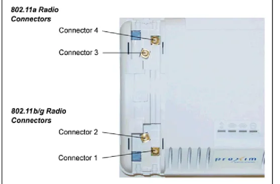
Figure 2-2 AP-4000/4000M/4900M Antenna Connectors
Connectors 1 and 2 are for the 802.11b/g radio; connectors 3 and 4 are for the 802.11a radio. When the AP is mounted on a wall, connectors 1 and 4 correspond to the horizontally polarized internal antenna, providing a coverage pattern parallel to the wall; connectors 2 and 3 correspond to the vertically polarized internal antenna, providing a coverage pattern parallel to the ceiling/floor. When the AP is mounted to a ceiling, connectors 1 and 4 correspond to the vertically polarized internal antenna, and connectors 2 and 3 correspond to the horizontally polarized internal antenna. Plugging an external antenna in to the antenna connector disables the corresponding internal antenna on the wireless interface. The AP continues to support antenna diversity with external antennas connected. With one external antenna connected to one of the two antenna connectors on a radio, one internal antenna and one external antenna are used for antenna diversity. With two external antennas connected, both external antennas are used for antenna diversity, and both internal antennas are disabled.
With external antennas connected, you may wish to manually select a particular antenna for use. To do so, disable antenna diversity by manually selecting which antenna to use for each wireless interface through the Command Line Interface. See Configure Antenna Diversity for information.
For a list of recommended antennas, see http://www.proxim.com/products/wifi/accessories. For installation instructions, see Installing External Antennas.
4.9 GHz Antenna
On the AP-4900M, antenna connector 3 is equipped with a pigtail adaptor for connection to a 4.9 GHz antenna. When the AP-4900M is configured to operate in the 4.9 GHz Public Safety operational mode, antenna diversity is automatically disabled, and antenna 3 is statically configured for use. Connecting an external antenna to this antenna port disables the corresponding internal antenna. For a list of recommended antennas, see
http://www.proxim.com/products/wifi/accessories. For installation instructions, see Attaching Antenna(s) to the AP-4900M for 4.9 GHz Operation.
Active Ethernet
AP-4000 Series Hardware Description
21 • The Active Ethernet (AE) integrated module receives ~48 VDC over a standard Category 5 Ethernet cable.
• To use Active Ethernet, you must have an AE hub (also known as a power injector) connected to the network. • The cable length between the AE hub and the Access Point should not exceed 100 meters (approximately 325 feet).
The AE hub is not a repeater and does not amplify the Ethernet data signal.
• If connected to an AE hub and an AC power simultaneously, the Access Point draws power from Active Ethernet. Also see Hardware Specifications.
NOTE: The AP’s 802.3af-compliant Active Ethernet module is backwards compatible with all ORiNOCO Active Ethernet hubs that do not support the IEEE 802.3af standard.
LED Indicators
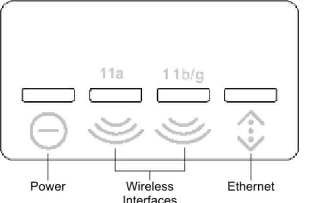
The top panel of the AP-4000/4000M/4900M has the following LED indicators.
Figure 2-3 LED Indicators on the AP-4000/4000M/4900M Top Panel The LED indicators exhibit the following behavior:
Indication Power Wireless Interface A (802.11a radio)
Wireless Interface B (802.11b/g radio)
Ethernet
Solid Green AP image running. Wireless interface A is preparing for use.
Wireless interface B is preparing for use.
Ethernet interface is connected at 100 Mbps with no traffic.
Blinking Green n/a Wireless interface A is transmitting or receiving wireless packets.
Wireless interface B is transmitting or receiving wireless packets.
Ethernet interface is connected at 100 Mbps with traffic.
Solid Amber The Bootloader is loading the application software.
n/a n/a Ethernet interface is
connected at 10 Mbps with no traffic.
Blinking Amber The AP is reloading. n/a n/a The Ethernet interface is connected at 10 Mbps with traffic. Solid Red Power On Self Test
(POST) running.
n/a n/a n/a
Blinking Red Rebooting. n/a n/a n/a
Power Wireless Interfaces
Prerequisites
Prerequisites
General Prerequisites
Before installing an AP-4000/4000M/4900M, you need to gather certain network information. The following table identifies the information you need.
Network Name (SSID of the wireless cards)
You must assign the Access Point a Network Name before wireless users can communicate with it. The clients also need the same Network Name. This is not the same as the System Name, which applies only to the Access Point. The network administrator typically provides the Network Name.
AP’s IP Address If you do not have a DHCP server on your network, then you need to assign the Access Point an IP address that is valid on your network.
HTTP Password Each Access Point requires a read/write password to access the web interface. The default password is “public”.
CLI Password Each Access Point requires a read/write password to access the CLI interface. The default password is “public”.
SNMP Read Password Each Access Point requires a password to allow get requests from an SNMP manager. The default password is “public”.
SNMP Read-Write Password Each Access Point requires a password to allow get and set requests from an SNMP manager. The default password is “public”.
SNMPv3 Authentication Password
If Secure Management is enabled, each Access Point requires a password for sending authenticated SNMPv3 messages. The default password is “public”. The default SNMPv3 username is administrator, with SHA authentication, and DES privacy protocol.
SNMPv3 Privacy Password If Secure Management is enabled, each Access Point requires a password when sending encrypted SNMPv3 data. The default password is “public”.
Security Settings You need to determine what security features you will enable on the Access Point. Authentication Method A primary authentication server may be configured; a backup authentication server is
optional. The network administrator typically provides this information. Authentication Server Shared
Secret
This is a password shared between the Access Point and the RADIUS authentication server (so both passwords must be the same), and is typically provided by the network administrator.
Authentication Server Authentication Port
This is a port number (default is 1812) and is typically provided by the network administrator.
Client IP Address Pool Allocation Scheme
The Access Point can automatically provide IP addresses to clients as they sign on. The network administrator typically provides the IP Pool range.
DNS Server IP Address The network administrator typically provides this IP Address. Gateway IP Address and
Subnet Mask
Prerequisites
23
Mesh Prerequisites
Before setting up a Mesh network, gather the following information:
Mesh Mode The mode in which the AP will be used. If the AP will be connected directly to the wired backbone, it should be configured for Mesh Portal mode; if it will connect to the Portal and backbone wirelessly, it should be configured for Mesh AP mode. If the AP will not be used in a Mesh network, Mesh Mode can be disabled.
Mesh Interface Number The interface on which the Mesh functionality will be enabled. For Wireless A, the interface number is 3; for Wireless B, the interface number is 4.
Mesh SSID The name of the Mesh network. The Mesh SSID should be between 1 and 16 characters.
Mesh Security Mode Mesh links may be secured through AES encryption. You may also choose to use Mesh functionality without security enabled.
Product Package
Product Package
Each AP-4000/4000M/4900M comes with the following:
• AP-4000/4000M/4900M unit (with integrated 802.11a radio and 802.11b/g radio, and Active Ethernet) • Power adapter
• One ceiling or wall mounting plate • Security cover
• One Installation CD-ROM that contains the following: – Software Installation Wizard
– ScanTool – MIBs
– User’s Guide in PDF format
– Xtras folder containing the following • SolarWinds® TFTP software • Ekahau™ Site Survey software • Acrobat® Reader software • One Quick Start Flyer
If any of these items are missing or damaged, please contact your reseller or Technical Support (see Technical Support for contact information).
System Requirements
To begin using an AP, you must have the following minimum requirements:
• A 10Base-T Ethernet or 100Base-TX Fast Ethernet switch or hub or cross-over Ethernet cable • At least one of the following IEEE 802.11-compliant devices:
– An 802.11a, 802.11b, or 802.11b/g client device
• A computer that is connected to the same IP network as the AP and has one of the following Web browsers installed: – Microsoft® Internet Explorer 6 with Service Pack 1 or later and patch Q323308
– Netscape® 7.1 or later
Hardware Installation
25
Hardware Installation
Required Materials
• AP-4000/4000M/AP-4900M unit • Mounting bracket with screws • Power adapter
• Security cover • Quick Start Flyer
Perform the following procedures to install the AP hardware: • Cabling the AP-4000/4000M/4900M
• Installing the Security Cover
• Mounting the AP-4000/4000M/4900M • Installing External Antennas
Cabling the AP-4000/4000M/4900M
Connect cables to the AP as follows: 1. Provide power to the AP, as follows:
a. Plug the power cord into the power jack (the left port) and connect the unit to an AC power outlet (100~240V, 50~60Hz).
b. If using Active Ethernet, connect power to the unit from a DC injector device, such as the ORiNOCO 1-Port Active Ethernet DC Injector hub.
NOTE:
Before installing and using this product, see the Regulatory Compliance section.
NOTE:
Avant l’installation et l’utilisation de ce produit, veuillez vous référer à la partie « Regulatory Compliance » (conformité aux réglementations).
NOTA:
Prima di installare ed utilizzare questo prodotto, fare riferimento alla sezione relativa alla “Regulatory Compliance” (conformità alle norme).
ANMERKUNG:
Bitte lesen Sie vor der Installation und Verwendung dieses Produkts im Abschnitt „Regulatory Compliance".
NOTA:
Antes de instalar y usar este producto, consulte la sección "Regulatory Compliance” (Cumplimiento de la normativa).
注記:
Hardware Installation
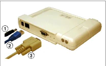
2. Attach one end of an Ethernet cable to the AP's LAN port (the center port, labeled “LAN”) and the other end to a network hub or switch.
3. Optionally, connect an RS-232 cable to the RS-232 console port (the right port, labeled “RS-232”). NOTE: You cannot install the security cover to the AP-4000/4000M/4900M if an RS-232 cable is connected.
Figure 2-4 Cabling the AP-4000/4000M/4900M 4. Verify LED Status
5. When the AP-4000/4000M/4900M boots, it performs a series of self-tests. 6. Wait for the power LED to turn green before proceeding.
Installing the Security Cover
You can optionally install a security cover to deter unauthorized access to the AP-4000. The security cover is a plastic cover that prevents access to the cabling and to the Reset and Reload buttons.
NOTE: You cannot connect an RS-232 cable to the AP-4000/4000M/4900M when a security cover is installed.
1. Slide the hinging end of the security cover into the hole on the rear panel of the AP-4000/4000M/4900M to the left of the connectors.
2. Use two screws to screw the right side of the security cover to the RS-232 screw holes on the rear panel of the AP-4000.
Mounting the AP-4000/4000M/4900M
Proxim recommends that you have a site survey professionally conducted to determine the best location for the AP. For professional site surveyors, Ekahau Site Survey software is included in the Xtras folder on the Installation CD-ROM. The following considerations must be kept in mind when the AP-4900M is mounted in a vehicle or outdoors:
• The AP must be protected from exposure, and the environmental conditions must be within those specified in the product datasheet that can be found at http://www.proxim.com/products/wifi/ap/. To most easily comply with these specifications, Proxim recommends mounting the AP-4900M in the passenger compartment of a vehicle or in a weatherproof NEMA box outdoors.
• When the AP is mounted within a vehicle, the metallic skin of the vehicle will retard the RF propagation of the AP. • Proxim recommends the 1086-PGTL adapter with an external vehicular antenna. For more information,, see
http://www.proxim.com/products/wifi/accessories.
Hardware Installation
27 Once you have chosen a final location for your unit, mount the AP-4000/4000M/4900M to a wall, to a T-bar ceiling, or in a vehicle as described below.
Mounting the AP-4000/4000M/4900M to a Ceiling
1. Attach the mounting plate to the bottom of the AP-4000/4000M/4900M by lining up the keyholes and attaching it with two screws.
2. Snap the tabs onto the ceiling T-bar. Rotate the AP-4000/4000M/4900M until it snaps on to the T-bar.
Figure 2-5 AP-4000/4000M/4900M Mounting Plate Mounting the AP-4000/4000M/4900M to a Wall
1. Put the mounting plate up to the wall. 2. Screw through the mounting plate.
3. Place the AP up against the mounting plate. Orient the AP with the long access vertical, with the connectors facing to the left.
Mounting the AP-4900M in a Vehicle
1. Attach the mounting plate up to the wall or to the wall partition (cage) behind the passenger seat in a vehicle. The knobs that fit into the keyholes on the AP-4900M should be in a vertical line.
2. Screw through the mounting plate.
Hardware Installation
Installing External Antennas
You can optionally install external antennas on the AP-4000/4000M/4900M. For information on the AP’s antenna functionality, see Antennas.
Follow the mounting instructions included with your external antenna, and then connect the antenna cable to the AP, as follows:
1. Press down near the center of the compartment covering and slide open the external antenna access compartments. The compartment closer to the LED panel contains the connectors for the 802.11b/g radio, and the other compartment contains the connectors for the 802.11a radio.
NOTE:AP-4000 models 8670-US2 and 8670-AU do not provide external antenna connectors for 5GHz (802.11a) operation.
Figure 2-6 Opening the Antenna Compartment
2. There are four antenna connectors in the AP-4000/4000M/4900M, labeled 1 through 4. Connectors 1 and 2 are for the 802.11b/g radio, and connectors 3 and 4 and for the 802.11a radio.Connect the antenna cable to connector 1 or 4 (the connector closer to the LED panel in the compartment), depending on the radio.
Hardware Installation
29 Figure 2-7 AP-4000/4000M/4900M Antenna Connectors
3. If installing a second external antenna on a radio, connect the antenna cable to connector 2 (802.11b/g radio) or connector 3 (802.11a radio).
4. Close the external antenna access compartments.
5. If desired, manually select which antenna(s) to use through the Command Line Interface. See Configure Antenna Diversity.
Attaching Antenna(s) to the AP-4900M for 4.9 GHz Operation
To attach an external antenna to the AP-4900M, attach the selected antenna to the pigtail attachment connected to the AP’s antenna connector 3 (see Figure 2-8).
For a list of recommended antennas, see http://www.proxim.com/products/wifi/accessories.
Figure 2-8 AP-4900M External Antenna Connection
Installing the AP in a Plenum
Hardware Installation
cables must comply with certain safety requirements, such as Underwriter Labs (UL) Standard 2043: “Standard for Fire Test for Heat and Visible Smoke Release for Discrete Products and Their Accessories Installed in Air-Handling Spaces”. The AP-4000/4000M/4900M has been certified under UL Standard 2043 and can be installed in the plenum.
Initialization
31
Initialization
The following sections detail how to initialize the AP using ScanTool, log in to the HTTP interface, perform an initial configuration of the AP using the Setup Wizard, and download the required AP software.
• Using ScanTool • Logging In
• Using the Setup Wizard • Installing the Software
Using ScanTool
ScanTool is a software utility that is included on the installation CD-ROM. It is an initial configuration tool that allows you to find the IP address of an Access Point by referencing the MAC address in a Scan List, or to assign an IP address if one has not been assigned.
The tool automatically detects the Access Points installed on your network, regardless of IP address, and lets you configure each unit’s IP settings. In addition, you can use set initial device parameters that will allow the AP to retrieve a new software to an AP that does not have a valid software image installed (see Client Connection Problems).
To access the HTTP interface and configure the AP, the AP must be assigned an IP address that is valid on its Ethernet network. By default, the AP is configured to obtain an IP address automatically from a network Dynamic Host
Configuration Protocol (DHCP) server during boot-up. If your network contains a DHCP server, you can run ScanTool to find out what IP address the AP has been assigned. If your network does not contain a DHCP server, the Access Point’s IP address defaults to 169.254.128.132. In this case, you can use ScanTool to assign the AP a static IP address that is valid on your network.
NOTE: Mesh APs must have static IP addresses, as the DHCP client will not function on wireless interfaces.
ScanTool Instructions
Follow these steps to install ScanTool and initialize the AP:
1. Locate the unit’s Ethernet MAC address and write it down for future reference. The MAC address is printed on the product label. Each unit has a unique MAC address, which is assigned at the factory.
2. Confirm that the AP is connected to the same LAN subnet as the computer that you will use to configure the AP. 3. Power up, reboot, or reset the AP.
The unit requests an IP Address from the network DHCP server.
4. Insert the Installation CD into the CD-ROM drive of the computer that you will use to configure the AP. The installation program will launch automatically.
5. Follow the on-screen instructions to install the Access Point software and documentation. NOTE:The ORiNOCO Installation program supports the following operating systems:
• Windows® 98SE • Windows® 2000 • Windows® NT • Windows® ME • Windows® XP
6. After the software has been installed, double-click the ScanTool icon on the Windows desktop to launch the program (if the program is not already running).
Initialization
NOTE:If your computer has more than one network adapter installed, you will be prompted to select the adapter that you want ScanTool to use before the Scan List appears. If prompted, select an adapter and click OK. You can change your adapter setting at any time by clicking the Select Adapter button on the Scan List screen. Note that the ScanTool Network Adapter Selection screen will not appear if your computer only has one network adapter installed.
Figure 2-9 Scan List
7. Locate the MAC address of the AP you want to initialize within the Scan List.
NOTE:If your Access Point does not show up in the Scan List, click the Rescan button to update the display. If the unit still does not appear in the list, see Troubleshooting for suggestions. Note that after rebooting an Access Point, it may take up to five minutes for the unit to appear in the Scan List.
8. Do one of the following:
• If the AP has been assigned an IP address by a DHCP server on the network, write down the IP address and click Cancel to close ScanTool. Proceed to the Logging In section for information on how to access the HTTP interface using this IP address.
NOTE:Mesh APs must be configured with static IP addresses. To assign the AP a static IP address, follow the steps below.
• If the AP has not been assigned an IP address (in other words, the unit is using its default IP address, 169.254.128.132), follow these steps to assign it a static IP address that is valid on your network: a. Highlight the entry for the AP you want to configure.
Initialization
33 Figure 2-10 Scan Tool Change Screen
c. Set IP Address Type to Static.
d. Enter a static IP Address for the AP in the field provided. You must assign the unit a unique address that is valid on your IP subnet. Contact your network administrator if you need assistance selecting an IP address for the unit.
e. Enter your network’s Subnet Mask in the field provided.
f. Enter your network’s Gateway IP Address in the field provided.
g. Enter the SNMP Read/Write password in the Read/Write Password field (for new units, the default SNMP Read/Write password is “public”).
NOTE:The TFTP Server IP Address and Image File Name fields are only available if ScanTool detects that the AP does not have a valid software image installed. See Client Connection Problems.
h. Click OK to save your changes.
i. The Access Point will reboot automatically and any changes you made will take effect. j. When prompted, click OK a second time to return to the Scan List screen.
k. Click Cancel to close the ScanTool.
Logging In
Once the AP has a valid IP Address and an Ethernet connection, you may use your web browser to monitor and configure the AP. (To configure and monitor using the command line interface, see Command Line Interface (CLI).) 1. Open a Web browser on a network computer.
– The HTTP interface supports the following Web browsers: • Microsoft® Internet Explorer 6 with Service Pack 1 or later • Netscape® 7.1 or later
2. If necessary, disable the browser’s Internet proxy settings. For Internet Explorer users, follow these steps: – Select Tools > Internet Options.
– Click the Connections tab. – Click LAN Settings.
Initialization
– Click OK twice to save your changes and return to Internet Explorer.
3. Enter the Access Point’s IP address in the browser’s Address field and press Enter or Go.
This is either the dynamic IP address assigned by a network DHCP server or the static IP address you manually configured. See Using ScanTool for information on how to determine the unit’s IP address and manually configure a new IP address, if necessary.
NOTE:Mesh APs must be configured with static IP addresses.
The Enter Network Password screen appears.
Figure 2-11 Enter Network Password
4. Enter the HTTP password in the Password field. Leave the User Name field blank. For new units, the default HTTP password is public.
If you are logging on for the first time the Setup Wizard will launch automatically.
NOTE:To prevent the Setup Wizard from launching upon log in, click on Management > Services and choose
Disable from the Setup Wizard drop down menu.
Initialization
35 Figure 2-12 System Status Screen
The buttons on the left of the screen provide access to the monitoring and configuration options for the AP. See Advanced Configuration to begin configuring the AP without using the Setup Wizard.
The Command Line Interface (CLI) also provides a method for monitoring and configuring the AP using Telnet or a serial connection. For more information about monitoring and configuring the AP with the CLI, see Command Line Interface (CLI).
Using the Setup Wizard
The first time you connect to an AP’s HTTP interface, the Setup Wizard launches automatically. The Setup Wizard provides step-by-step instructions for how to configure the Access Point’s basic operating parameters, such as Network Name, IP parameters, system parameters, and management passwords.
Initialization
Setup Wizard Instructions
1. Click Setup Wizard to begin. The Setup Wizard supports the following navigation options:
• Save & Next Button: Each Setup Wizard screen has a Save & Next button. Click this button to submit any changes you made to the unit’s parameters and continue to the next page. The instructions below describe how to navigate the Setup Wizard using the Save & Next buttons.
• Navigation Panel: The Setup Wizard provides a navigation panel on the left-hand side of the screen. Click the link that corresponds to the parameters you want to configure to be taken to that particular configuration screen. Note that clicking a link in the navigation panel will not submit any changes you made to the unit’s configuration on the current page.
• Exit: The navigation panel also includes an Exit option. Click this link to close the Setup Wizard at any time.
CAUTION:If you exit from the Setup Wizard, any changes you submitted (by clicking the Save & Next button) up to that point will be saved to the unit but will not take effect until it is rebooted.
2. Configure the System Configuration settings and click Save & Next. See System for more information. 3. Configure the Access Point’s Basic IP address settings, if necessary, and click Save & Next. See Basic IP
Parameters for more information.
4. Assign the AP new passwords to prevent unauthorized access and click Save & Next. Each management interface has its own password:
• SNMP Read Password • SNMP Read-Write Password • CLI Password
• HTTP (Web) Password
By default, each of these passwords is set to “public”. See Passwords for more information. 5. Configure the basic Wireless Interface Configuration settings:
• Select the Operational Mode as follows and click Save & Next:
The Wireless-A interface operates only in 802.11a mode on the AP-4000/4000M and in either 802.11a mode or 4.9 GHz Public Safety mode on the AP-4900M. The Wireless-B interface can be configured to operate in the following modes:
— 802.11b mode only: The radio uses the 802.11b standard only.
— 802.11g mode only: The radio is optimized to communicate with 802.11g devices. This setting will provide the best results if this radio interface will only communicate with 802.11g devices.
— 802.11b/g mode: This is the default mode. Use this mode if you want to support a mix of 802.11b and 802.11g devices.
— 802.11g-wifi: 802.11g-wifi has been defined for Wi-Fi testing purposes. It is not recommended for use in your wireless network environment.
In general, you should use either 802.11g only mode (if you want to support 802.11g devices only) or 802.11b/g mode to support a mix of 802.11b and 802.11g devices.
• Configure the following available options and click Save & Next:
— Primary Network Name (SSID): Enter a Network Name (between 1 and 32 characters long) for the wireless network. You must configure each wireless client to use this name as well. Note that the
AP-4000/4000M/4900M supports up to 16 SSIDs and VLANs per wireless interface (radio). Please see the Advanced Configuration chapter for information on the detailed rules on configuring multiple SSIDs, VLANs, and security profiles.
Initialization
37 — Auto Channel Select: By default, the AP scans the area for other Access Points and selects the best
available communication channel, either a free channel (if available) or the channel with the least amount of interference. Remove the check mark to disable this option. See Dynamic Frequency Selection/Radar Detection (DFS/RD) for information and Available Channels for a list of available channels.
NOTE:When an AP is configured to function as a Mesh AP, its channel will depend on the channel of its neighbors.
— Frequency Channel: When Auto Channel Select is enabled, this field is read-only and displays the Access Point’s current operating channel. When Auto Channel Select is disabled, you can specify the Access Point’s channel. If you decide to manually set the unit’s channel, ensure that nearby devices do not use the same frequency. Available Channels vary based on regulatory domain. See Dynamic Frequency Selection/Radar Detection (DFS/RD) for details more information and Available Channels for a list of available channels. NOTE:When an AP is configured to function as a Mesh AP, its channel will depend on the channel of its
neighbors.
— Transmit Rate: Use the drop-down menu to select a specific transmit rate for the AP-4000/4000M/4900M’s radios. The Auto Fallback feature allows the AP to select the best transmit rate based on the cell size.
— For the 802.11a radio operating in 802.11a mode, choose between 6, 9, 12, 18, 24, 36, 48, 54 Mbits/s, and Auto Fallback.
— For the 802.11a radio operating in 4.9 GHz Public Safety mode, choose between 6, 9, 12, 18, 24, 36, 48, 54 Mbits/s, and Auto Fallback.
— These transmit rates are based on a 20 MHz channel bandwidth (the default). Additional rates are available with 10 MHz channel bandwidths. To select alternate bandwidths and transmit rates, see Operational Mode.
— For the 802.11b/g radio operating in 802.11b mode, choose between 1, 2, 5.5, 11 Mbits/s, and Auto Fallback.
— For the 802.11b/g radio operating in 802.11g mode, choose between 6, 9, 12, 18, 24, 36, 48, 54 Mbits/s, and Auto Fallback.
— For the 802.11b/g radio operating in 802.11b/g mode, choose between 1, 2, 5.5, 6, 9, 11, 12, 18, 24, 36, 48, 54 Mbits/sec, and Auto Fallback.
— For the 802.11b/g radio operating in 802.11g-wifi mode, choose between 6, 9, 12, 18, 24, 36, 48, 54 Mbits/s, and Auto Fallback.
NOTE: 802.11g-wifi has been defined for Wi-Fi testing purposes. It is not recommended for use in your wireless network environment.
Additional advanced settings are available in the Wireless Interface Configuration screen.See Interfaces for details. See Security Profile for a description of security features, Management VLAN for a description of VLAN capabilities, and Configuring Security Profiles for detailed configuration procedures.
6. Review the configuration summary. If you want to make any additional changes, use the navigation panel on the left-hand side of the screen to return to an earlier screen. After making a change, click Save & Next to save the change and proceed to the next screen.
7. When finished, click Reboot on the Summary screen to restart the AP and apply your changes.
Installing the Software
Proxim periodically releases updated software for the AP on its Web site, http://support.proxim.com (Knowledgebase Answer ID 1250). Proxim recommends that you check the Web site for the latest updates after you have installed and initialized the unit.
Download the Software
Initialization
2. If prompted, create an account to gain access.
NOTE:The Knowledgebase is available to all website visitors. First-time users will be asked to create an account to gain access.
3. Click Search Knowledgebase.
4. In the Search Knowledgebase field, enter 1250.
5. From the Search By drop-down menu, select Answer ID. 6. Click Search.
7. Click on the appropriate link to download the software.
8. Use the instructions in the following sections to install the new software.
Install Software with HTTP Interface
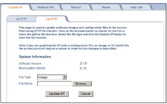
Use the Update AP via HTTP tab to update the AP with the latest software image. 1. Click Commands > Update AP > via HTTP.
Figure 2-14 Update AP via HTTP Command Screen 2. From the File Type drop-down menu, select Image.
3. Use the Browse button to locate or manually type in the name of the file (including the file extension) the file you downloaded from the Proxim Knowledgebase. If typing the file name, you must include the full path and the file extension in the file name text box.
4. To initiate the HTTP Update operation, click the Update AP button.
A warning message is displayed that advises the user that a reboot of the device will be required for changes to take effect.
Initialization
39 5. Click OK to continue with the operation or Cancel to abort the operation.
6. If the operation is unsuccessful, you will receive an error message. If this occurs, see the Troubleshooting chapter or attempt installing the software with a TFTP server, as described in the next section.
7. If the operation is successful, you will receive a confirmation message. For installation changes to take effect, reboot the AP as follows:
• Click Commands > Reboot. • Enter 0 in the Time to Reboot field. • Click OK.
Install Software with TFTP Server
A Trivial File Transfer Protocol (TFTP) server allows you to transfer files across a network. You can upload files from the AP for backup or copying, and you can download the files for configuration and AP Image upgrades. The Solarwinds TFTP server software is located on the ORiNOCO AP Installation CD-ROM. You can also download the latest TFTP software from Solarwind’s Web site at http://www.solarwinds.net.
NOTE: If a TFTP server is not available in the network, you can perform similar file transfer operations using the HTTP interface.See Update AP via HTTP.
After the TFTP server is installed:
• Check to see that TFTP is configured to point to the directory containing the AP Image.
• Make sure you have the proper TFTP server IP address, the proper AP Image file name, and that the TFTP server is operational.
• Make sure the TFTP server is configured to both Transmit and Receive files, with no automatic shutdown or time-out. The following types of files can be downloaded to the AP from a TFTP server:
• Config (configuration file)
• Image (AP software image or kernel)
• UpgradeBspBl (BSP/Bootloader firmware file) • License file
• SSL Certificate • SSL Private Key • SSH Public Key • SSH Private Key • CLI Batch File
Install Updates from your TFTP Server using the Web Interface
1. Download the latest software from http://support.proxim.com (Knowledgebase Answer ID 1250). See Download the Software for instructions).
2. Copy the latest software updates to your TFTP server.
3. In the Web Interface, click the Commands button and select the Download tab. 4. Enter the IP address of your TFTP server in the field provided.
5. Enter the File Name (including the file extension). Enter the full directory path and file name. If the file is located in the default TFTP directory, you need enter only the file name.
6. Select the File Type from the drop-down menu (use Img for software updates). 7. Select Download & Reboot from the File Operation drop-down menu.
Related Topics
Install Updates from your TFTP Server using the CLI
1. Download the latest software to http://support.proxim.com (Knowledgebase Answer ID 1250). See Download the Software for instructions).
1. Copy the latest software updates to your TFTP server. 2. Open the CLI interface via Telnet or a serial connection. 3. Enter the CLI password when prompted.
4. Enter the command: download <tftpaddr> <filename> img
The download will begin, and the image will be downloaded to the Access Point. 5. When the download is complete, type reboot 0 and press Enter.
NOTE: See Command Line Interface (CLI) for more information.
Related Topics
The Setup Wizard helps you configure the basic AP settings required to get the unit up and running. The AP supports many other configuration and management options. The remainder of this user guide describes these options in detail. • See Advanced Configuration for information on configuration options that are available within the Access Point’s
HTTP interface.
• See Monitoring for information on the statistics displayed within the Access Point’s HTTP interface. • See Commands for information on the commands supported by the Access Point’s HTTP interface. • See Troubleshooting for troubleshooting suggestions.
41
3
System Status
The first screen displayed after Logging In is theSystem Status screen. You can always return to this screen by clicking the Status button.
Figure 3-1 System Status Screen
The System Status screen provides the following information:
• System Status: This area provides system-level information, including the unit’s IP address and contact information. See System for information on these settings.
• System Alarms: System traps (if any) appear in this area. Each trap identifies a specific severity level: critical, major, minor, and informational. See Alarms for a list of possible alarms.