Fiber Prepreg and Stainless Steel Reinforced P.M.M.A. Denture Base
journal or
publication title
福井大学工学部研究報告
volume 25
number 2
page range 171‑178
year 1977‑09
URL http://hdl.handle.net/10098/4520
A study on the Bending Characters of Carbon Fiber Prepreg and Stainless Steel Reinforced P.M.M.A. Denture Base
Hiroshi KIMURA*, Takuji YAMAGUCHI*, Tetsuro SHIRAISHI*, Masakazu TSUBOKAWA*, Mitsuru TAKEUCHI*
(Received June 11, 1977)
In this paper we describe an experimental study on the reinforce- ment effects of the carbon fiber prepreg and stainless steel rein- forced P.M.M.A. for mandible resin base. As a result of this series of test and experiments, i t was found that the reinforcement rods are not effective on the center in the mandible resin base model, and that the effective position of reinforcement rods would like to take on the outside in the mandible base model section. It was also found that the reinforcement mandible resin base have not separate failure.
1. INTRODUCTION
There are cases where rods for reinforcement are inserted in the cen- ter of resin base section to reinforce mandible resin base. In order to find if carbon fiber having excellent features as high strength, high elastic modulus, light weight, anti-corrosion, etc. can be used as rods for reinforcement~~~tudies are made in this article with regard to effect of the reinforcement rods used for mandible resin base, in comparison with resin base inserted with reinforcement rods of flat- tened conventional stainless steel wire and P.M.M.A. resin base without any reinforcement rods.
2. EXPERIMENTAL MATERIALS AND EXPERIMENTAL METHOD
Experimental materials were made of carbon fiber (T300) reinforced P.M.M.A. mandible resin base, stainless steel wire reinforced P.M.M.A.
mandible resin base and non-reinforced P.M.M.A. mandible resin base.
And then, the carbon fiber were made of carbonized acrylic fiber (more
* Dep. of Textile Eng.
prepreg.
Tensile strength (kg/mm ), fiber direction
Tensile elastic modulus (ton/mm2) , fiber direction Bending strength (kg/mm2) , fiber direction
Bending elastic modulus (ton/mm2) , fiber direction Compressive strength (kg/mm2) , fiber direction
compressive elastic modulus (ton/mm2) , fiber direction Poisson's ratio
Interlaminar shearing strength (kg/mm2)
Izod impact value (kg'cm/cm'notch)
Bending creep (80% load of average strength), fiber direction
Bending creep fracture strength (for 500 hr), fiber direction
Tensile fatigue strength (107cycles) Rockwell hardness (E scale)
Barcol hardness
Coefficient of friction (parallel to fiber) PV value (kg/cm2'm/min)
Steady abrasion modulus (PV=500) (mg/hr.cm2)
Heat conductivity (Kcal/m/h/oc), fiber direction Heat conductivity (Kcal/m/h/oc), normal to fiber Coefficient of linear expansion
direction
Coefficient of linear expansion fiber
Specific heat (cal/g/oc)
/oc), fiber /oc), normal to
Specific resistance of volume (n·cm), fiber direction Specific resistance of volume (Q·cm), normal to fiber
140 13 140 13 100 13 0.3
8 110 below 10% of static strain for 500 hr above 80% of static strength above 60 kg/mm2
90 70 0.25 1000
2 4 0.40 -1 X 10⁻⁷
0.16 0.005 5.7 Carbon fiber content ratio: 60%vol (after hardening) Condition of hardening 170 DC 1 hr, post cure
170 DC 2 hr
than 250kg/mm2 in strength and more than 22ton/mm2 in elastic modulus}
(3000filaments) as a base (57wt.%). Table I shows general properties of Prepreg P301 (epoxy resin 828, Shell Chemical Co., hardener BFg-MEA) as carbon fiber reinforced bar~ P.M.M.A. were room temperature polymeriza- tion type and heat polymerization type of denture acrylic resin.
Experiments were carried out with model of mandible resin base, using (I) autograph and electric resistance strain.meter for bending test in small and large deformation ranges, (2) load apparatus made by the author and electric resistance strain meter for bending and torsion
test, (3) weight-dropping tester made by the author, electric resis- tan.ce dynamic strain meter and electro-magnetic oscillograph for weight- dropping test and (4) concrete base for drop test. On the other hand, other experiments were also conducted to find out effect of reinforce- ment rods inserted in different positions in resin base sectiGn: i.e.
reinforcement rods were inserted (1) on the upper side, (2) on the lower side, (3) in the center, (4) between the upper side and the center and (5) between the lower side and the center, respectively of 100 x 10 x 8 mm beams, and these beams were then undergone bending test, supported at both ends and load applied at the center. Fig.l shows
positions of reinforcement rods inserted in the mandible base model sections used for the experiments to find out reinforcement effect in relation to arrangement of
the reinforcement rods.
3. EXPERIMENTAL RESULTS AND CONSIDERATION Fig.2 shows result of bending test in small defor- mation range, from which i t has become clear that rela- tions between stress and load at each position are same and can be expressed in straight line irrespective of with or without reinforce- ment rods, that stress in the axial direction is larger than stress in the right angle direction, and that maximum stress appears at the central part in the axial direction. Results of experi- ment in which relations bet- ween bending load and deflec- tion in large deformation range were sought are shown in Fig.3, from which i t has become clear that relations between bending load and deflection are same and have
' .
f-- 50 - -I
50 ~. ' l---
100 ~~ ~
NO.2 PMMA+SUS
I::JlI
NO.4 PMMA+SUS
~
NO.6 PMMA+SUS
NO.8 ?"t."tA+SUS
g
. 10.3--J :
,:;~O. 3 P~1A+CF
r-::w
No.5
~
PMMA+CFr=-TI
~O.
~
7 PMMA+CF.NO.9 P!-1MA+CF
Fig.l Constitution and dimension of the carbon fiber (CF) and stainless steel (SUS) rein- forced P.M.M.A. construction.
O.B ~---+---~-+---+---~--4- '10.3
• PMMA
0.6
III
~ 0.2 ... I..
u:
o
o SUS () CF
I\-A Section
~
. '3 1 IJ :
11-1
o 0 2 0 2 4 Load (kq)
_o.~ I =t5 I" 1:f CEil
Fig.2 Relation between stress and bending load on the each lower jaw resin base. (SUS:stainless steel reinforced P.M.M.A. base, CF:carbon fiber reinforced P.M.M.A. base.)
tendency to be represented in straight line irrespective of with or without reinforcement rods and that the resin base fails after showing deflection when applied to load, although the resin base having reinforce- ment rods is approximately two times stronger than the resin base of P.M.M.A. only. From these results, i t has come to our knowledge that to have or not to have reinforcement rods has no effect in reinforcement in small deformation range, while the rods are quite effec- tive in terms of reinforcement in large deformation range, and that there is no difference in
20~---~r---~---1
15
.:o~JS
CF
x"
=10~---~~~g---~r---~
"0
<0 ..:I o
5~---JL-~---~---~
2 4 6
Deflection (rom)
Fig.3 Relation between bending load and deflection in large deformation range on-the each lower jaw resin base.
reinforcement effect between carbon fiber and stainless steel. Fig:4 shows the results of experiment in which relations between stress and load where bending and torsion were simultaneously applied were sought for. From these results, i t has become apparent that relations between such load and stress show the same tendency expressable in straight line in small deformation range, irrespective of with or without rein-
0.6r---.---~---or---._---r_----_,---~---._--__,
NO.1 NO.2 NO.3
~ 0.4~----+---+_--~~---~----~-/~~-_+---~----~~~
"'-c-
.!><:
Ul
~ 0.2~----~--~~~---~---+A~---~----_1---_+---_r--~
H +J Ul
2 4 o 2
Load (kg)
4 o
• PMMA
o SUS () CF
2 4
Fig.4 Relation between torsional bending load (I) and stress on the each lower jaw resin base.
0.6
NO.1
01
F: 0.4
"- t;, .y.
rJl Ul OJ H 0.2
~J (/J
2 4 o 4
Load (kg)
o
• PMMA
o SUS
() CF
NO.3
2 4
Fig.5 Relation between torsional bending load (IT) and stress on the each lower jaw resin base.
point (No.2). Fig.5 shows the results of the same experiment as the one shown in Fig.4, with the only exception that the supporting point is
'"
.
or-t x·'
8000 ---.---~
1'f.1t1A
4000
o
- - -
sus
j
CF~
P.M.M.A. bdse
a
- t stainless steel reinforced P.M.M.A. base
Carbon fiber reinforced P.M.M.A. base
t
:
~.I .8
~t Fig.6 Oscillograph record on the concrete block drop test at IOcm hight.
moved to No.3. Results of this experiment were also very similar to those of the preceding experi- ment except that the maximum stress appears not at the suppor- ting point but at No.2, which seems to be un account of the shape and size of central section of the mandible resin base. Fig.6 shows oscillographs of dynamic strain meter when a concrete block was dropped on to the resin bases from the height of IOcm as shown on illustration. From these oscillographs, i t is found that any resin base has the same
tendency and no effect of rods in reinforcement is ascertained.
Results of experiment in which
;Jl til
3 ~---"
~ 2 1 - - - - 1
...,
til ty\
. ..., C 'C C
f) NO.9
~ NO.8
e NO.7
e NO.6 Q ~O.5
~ NO.4 () NO.3
o NO.2
• NO.1
OL---______ ~ __________ ~ __ ~
o 1
Def1ection(mm) 2
Fig.? Relation between apparent bending stress and deflec- tion.
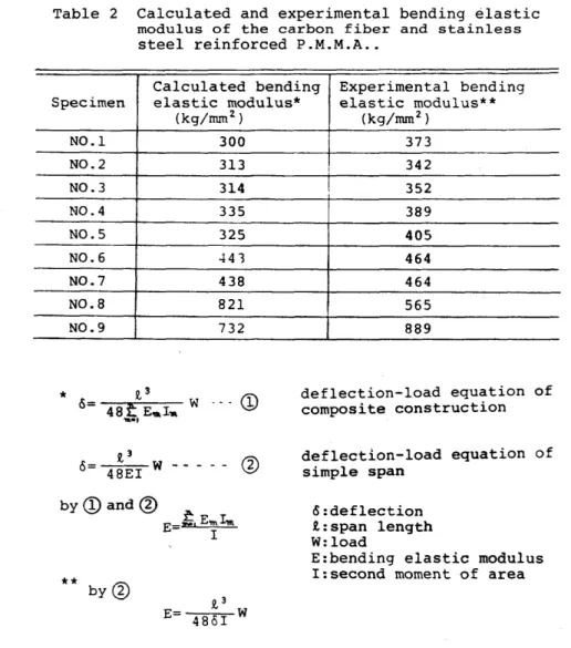
Table 2 Calculated and experimental bending elastic modulus of the carbon fiber and stainless steel reinforced P.M.M.A ..
Calculated bending Experimental bending Specimen elastic modulus*
(kg/mmz)
NO.1 300
NO.2 313
NO.3 314
NO.4 335
NO.5 325
NO.6 441
NO.7 438
NO.8 821
NO.9 732
*
0= t 3 W - - -CD
48t E ... I ..
,...,
** by@
elastic modulus**
(kg/mm2 )
373
I 342
352 389 405 464 464 565 889
deflection-load equation of composite construction deflection-load equation of simple span
6:deflection R.:span length W: load
E:bending elastic modulus I:second moment of area
position of insertion of reinforcement rods was changed using the man- dible resin base model to find the effect thereby in reinforcement are shown in Fig.7, from which i t has been found that rods are not effec- tive in terms of reinforcement at all when they are placed in the center, while the farther they are placed from the center, the more they become effective. When the rods are placed outmost, reinforcement effect is biggest, giving C.F. reinforced base about 2.5 times of the rigidity. Bending elastic modulus obtained by theoretical and experi- mental methods is shown in Table 2, which you will find is similar to the results of experiment in Fig.7.
The following summary can be made from the results of the present research. As a result of this series of experimental and theoretical methods, i t was found that.
1) The reinforcement rods are not effective on the center in the mandible resin base model.
2) The reinforcement mandible resin base have not separate failure.
3) The effective position of reinforcement rods would like to take on the outside in the mandible base model section.
ACKNOWLEDGMENTS
The authors wish to express his sincere thanks to Prof. Dr. Y.Kawamura, Prof. Dr. S.Kawai, Dr. Y.Okuno and Dr. H.Matsushiro of Osaka University for their encouragements and valuable discussions.
The authors would like to express sincere thanks to Mr. Osamu Takigawa of Tore Co. Ltd. for preparing to experimental materials.
REFERENCES
1) H.Kimura, T.Yamaguchi, T. Shiraishi , M.Tsubokawa, M.Takeuchi, S.Kawai, Y.Okuno and H.Matsushiro: The Journal of the Japan Research Society of Dental Materials & Appliances, Vol.33, No.3, p.297-305, 1976.
2) H. Kimura, T. Yamaguchi, T. Shiraishi, M. Tsubokawa, M. Takeuchi, S. Kawai"
Y.Okuno and H.Matsushiro: The Journal of the Japan Research Society of Dental Materials & Appliances, Vol.33, No.4, p.350-358, 1976.
3) Tore: Technical Sheet of Carbon Fiber Toreca, CF-08Rl, 1972, CF-06Rl, 1972.
4) H.Miyairi, M.Nagai and A.Muramatsu: Mechanical Properties of Dental Material Laminated with Organic Fiber Reinforced Plastics, The 1975
Symposium on Biomaterials, Kyoto University, Aug., 29-30, 1975.