Composites of Thin Plate
journal or
publication title
福井大学工学部研究報告
volume 25
number 2
page range 153‑160
year 1977‑09
URL http://hdl.handle.net/10098/4518
A Study on the Self Adhesion of Carbon Fiber Prepreg and Dental Acrylic Resin on the Hybrid Composites of Thin Plate
Hiroshi KIMURA*, Takuji YAMAGUCHI*, Tetsuro SHIRAISHI*, Masakazu TSUBOKAWA*, Mitsuru TAKEUCHI*
(Received June 11, 1977)
In this paper we describe an experimental study, this articles is to report, making by coalescence in the course of reaction hardening process of hybrid composite of carbon fiber (C.F.) prepreg not hardened yet and polymethyl methacrylate (P.M.M.A.) of not polyme- rized yet was experimented, thence coalesced hybrid composite was subjected to bending test to check in comparison with material of adhered construction and simple plates of C.F. and P.M.M.A ..
As a result of this series of tests and experiments, i t was found that. Self-adhered hybrid materials showed very excellent bending characteristics as in the case of adhered materials.
1. INTRODUCTION
It was reported in the previous articles that the hybrid composite in the form of sandwich or canape construction of C.F. prepreg and acrylic resin had excellent bending rigidity and bending strength compared with resin base of P.M.M.A. simple substance and had rigidity of 16 times as much of rigidity of P.M.M.A. simple plate.l),~ It was also reported that hybrid thin plate composite of C.F. and P.M.M.A. in the range of
O.9rnrn could be easily made and that even thin plate in such thickness
had rigidity of 16 times as much of that of P.M.M.A. simple plate.l),~
Such hybrid composite was made of C.P. plate and P.M.M.A. plate adhered to each other by epoxy resin. In this article, making by coalescence in the course of reaction hardening process of hybrid composite of C.F.
prepreg not hardened yet and P.M.M.A. of not polymerized yet was experi- mented, thence coalesced hybrid composite was subjected to bending test to check in comparison with material of adhered construction and simple
* Dep. of Textile Eng.
2. EXPERIMENTAL PROCEDURES
Hybrid composite of sandwich construction of about lmm in total thickness having C.F.S) layers of 0.15 and 0.36mm on both sides and
P~M.M.A. layer as core was made by self-adhesion. Namely, hybrid plates made by self-adhesion by combination of C.F. prepreg - P.M.M.A.
preform, C.F. prepreg - P.M.M.A. plate and C.F. plate - P.M.M.A.
preform, C.F. simple plate, P.M.M.A. simple plate, and C.F. plate
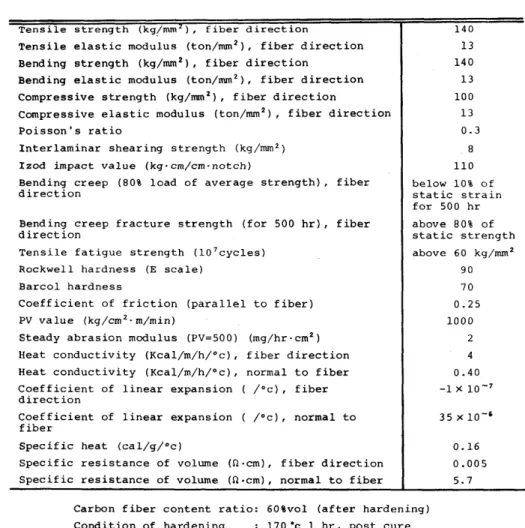
Table 1 General properties of carbon fiber reinforced prepreg.
Tensile strength (kg!rom ), fiber direction
Tensile elastic modulus (ton/mm2) , fiber direction Bending strength (kg/mm2) , fiber direction
Bending elastic modulus (ton/mm2) , fiber direction Compressive strength (kg/mm2) , fiber direction
Compressive elastic modulus (ton/mm2) , fiber direction Poisson's ratio
Interlaminar shearing strength (kg/mm2 )
Izod impact value (kg'cm/cm'notch)
Bending creep (80% load of average strength), fiber direction
Bending creep fracture strength (for 500 hr), fiber direction
Tensile fatigue strength (107cycles) Rockwell hardness (E scale)
Barcol hardness
Coefficient of friction (parallel to fiber) PV value (kg/cm2'm/min)
Steady abrasion modulus (PV=500) (mg/hr·cm2)
Heat conductivity (Kcal/m/h/oc), fiber direction Heat conductivity (Kcal/m/h/oc), normal to fiber Coefficient of linear expansion
direction
Coefficient of linear expansion fiber
Specific heat (cal/g/oc)
/Oc), fiber /Oc), normal to
Specific resistance of volume (n·cm), fiber direction Specific resistance of volume (n·cm), normal to fiber
140 13 140 13 100 13 0.3
8 110 below 10% of static strain for 500 hr above 80% of static strength above 60 kg/mm2
90 70 0.25 1000
2 4 0.40 -1)( 10-7
0.16 0.005 5.7 Carbon fiber content ratio: 60%vol (after hardening) Condition of hardening 170·c 1 hr, post cure
170·c 2 hr'
P.M.M.A. plate (adhered) were bend-tested to find deflection and bending stress, as well as deflection and maximum stress on outside.
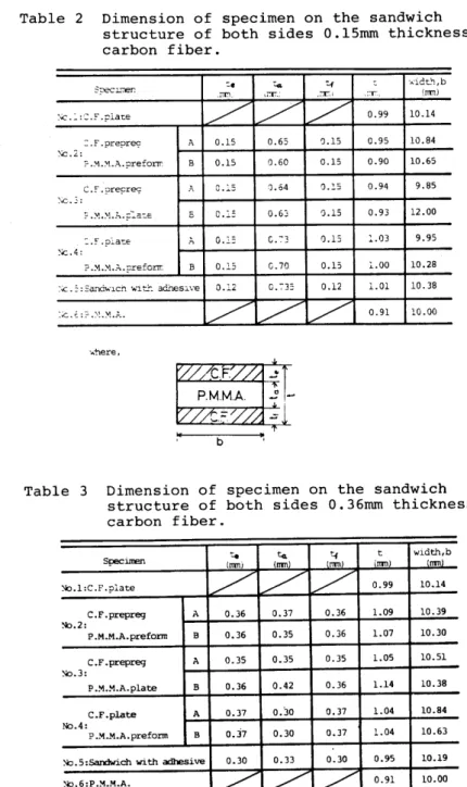
Table 1 shows general properties of carbon fiber reinforced prepreg used for these experiments, and Table 2-3 show the dimensions of speciments of sandwich construction used for these experiments. C.F. plate was
Table 2 Dimension of specimen on the sandwich structure of both sides O.15mm thickness carbon fiber.
= . F . prepre<?
X:.2:
C~F .:?re~re.::
';(:. ~:
~c.4:
A B
E ::e
,;T.\_
/
0.15 0.15 C .. :5
o .I:
0.2.:
0.l5 0.12
/
:..
\;:r.
/
0.65 0.6'l :).64 0.63 C. :'3 G.70
D. :-3:
/
':.f
.::17.1
/
'l.15 'l.15
'l.~S
0.15 0.15 0.15 0.12
V
,:T_,
0.99 0.95 'l.9'l 'l.94 0.93 :.03 :i..00 l.01 0.91
-A-idt-'1,b
\rrrn)
10.14 10.84 10.65 9.85 12.00 9.95 10.28 10.38 10.00
Table 3 Dimension of specimen on the sandwich structure of both sides O.36mm thickness carbon fiber.
te
(::l
':.f t width,bSpecimen (rrrnj Irrrn) (rrrn) 'rrrnl
~.1:C.F.p1ate
/ / V
0.99 10.14C.F • prepreg A 0.36 0.37 0.36 l.09 10.39
~.2:
P .M.M.A. preform B 0.36 0.35 0.36 l.07 10.30
C.F .prepreg A 0.35 0.35 0.35 1.05 10.51
~.3:
P .!-1.!-1.A. plate B 0.36 0.42 0.36 1.14 10.38
C.F.plate A 0.37 0.30 0.37 1.04 10.84
No.4:
P.!o1.!o1.A.preform B 0.j7 0.30 0.37 1.04 10.63
)lc. 5: SarKiwich with adhesive 0.30 0.33 0.30 0.95 10.19
~.6:P.!o1.M.A.
~ 7 /
0.91 10.00of furnace, thence heating again for after-cure for 125 minutes in 170°c. Coalescence of C.F. prepreg and P.M.M.A. preform was carried out by putting tetron film of lmm thick and tetron cloth on mold, onto which set were C.F. prepreg, P.M.M.A. not hardened yet and C.F. prepreg, thence hardening process as stated above was applied. P.M.M.A. plate was prepared by heating and pressurizing in 100°c for 40 minutes and under 100kg/cm2 respectively after filling resin into mold, thence cooled down naturally. Coalescence process of C.F. plate with P.M.M.A.
preform and C.F. prepreg with P.M.M.A. plate were carried out under molding conditions of P.M.M.A. plate and of C.F. plate respectively.
Coalesced specimens were subjected to three-point bending test with span length of 50mm and load applied to the center.
3. EXPERIMENTAL RESULTS AND CONSIDERATION
Figs.l and 2 show deflection, apparent stress and maximum stress on
N~.4
7-
1 _--+ _ _ _ _ A ~ 0 .350l----+--j I): ""'
1 ~1---4 1- -j
a~---l
~ .A /"J)('~o
0~
30!f~~
f llfttl:~:f{JZ:;;:~"m
~20
1--f~~ ~ No3:0{~~~~~~~
/
III .... ,. A \c.Fplat~
C ,_: PM.M.A.pr~lorm
a" .A~ No.5:. Sandwich with adhesive
~ LA~
<1=M=lLw No.6:. PM.MA~ :: 2bf
10 -- ---+---+---~
tl I
1.0 2.0
Deflection 3.0 (mm)
4.0
Fig.l Relation between apparent bending stress and deflec- tion on the sandwich structure of both sides 0.15mm thickness C.F ..
()~6
~ Broken
() I
°0~=---~1~.0---~2~D---3~.0---~4.0 Deflection (mm)
Fig.2 Relation between maximum stress of tension side and deflection on the sandwich structure of both sides 0.15mm thickness C.F ..
tensile side observed under three-point bending with regard to speci- mens of sandwich construction having C.F. layers of O.15mm thick on both sides. In comparison with P.M.M.A. plate, self-adhered hybrid composites and C.F. plate had bending rigidity of about 17 and about 39 times as much respectively, while maximum stress on outside under the same deflection of self-adhered hybrid composite and C.F. plate was about 24 and about 38 times respectively as much of maximum stress of P.M.M.A. plate. There were little differences among specimens by different self-adhesion or different adhesion methods, and any of the self-adhesion methods proved to be effective. Table 4 presents theore- tical elastic modulus obtained by combination beam theory and apparent elastic modulus obtained through experiments, all with each hybrid
Table 4 Calculated and experimental apparent bending elastic modulus for the sandwich structure of both sides O.15mm thickness carbon fiber.
calculated benii.ng Elq:er:urental . beRling Spec:inE!n elastic m:xiulus elastic ll1Xiulus
(kg/mnl) * (k~)
~.l:C.F.plate 13000 15572
C.F .prepreg A 8823 6234
~.2:
P.M.M.A.prefonn B 9240 7559
C.F .prepreq A 9034 6471
No.]:
P.M.M.A.plate B 8962 5594
C.F.p1ate A 8834 6917
~.4:
P .M.M.A.prefonn B 8644 7U5
~.5:Sandwich with adhesive 7355 6766
~.6:P.M.M.A. ]00 289
* 5=48:.r.,r. w l' ---(D Deflectial-laad equaticn of sandwich beam.
5= 4tr w - - - -
m
0eflectia1-1011d equaticn of unifor;m section beam.where,
o :Deflectiat.
L :Span length (S«bD).
w :IDad.
E .. :Younq'S lIIldulus for individual cx:mp:nents.
? .M.M.A. : ]00kg/nm' C.F. : 13000kg/nm&
r.:Seccndary m:ment of area for individual~.
5o1---1-
50t---+-i!;~,
NE
~40~---
~ 01
hi ~
t /;/
::
r~---~~7/~ --~---~r---~~ .l;j J.y~ ~ • ...
No.2::xJC.U:.,a'.
F.prE'prp9 1/11/1 ~ 30 iii . !: 01
"0
c GI .£) 20 C GI
o
a.« a. 10
No.l:_ CFplatp No.2:xlCF prppr P9
\P.MMApr.farm
ICF pr E'prt'g No.3:o \PM-M.A.p1at.
NoIo·6!C.Fplatp . \PMMApr.form No5:& Sandwich with adhE'siv.
No.6: _ P.M.M.A
1.0 2.0
Deflection
3.0 (mm)
4.0
~ 30 ~b
- '
lp.M.MApr.form'iii [I No3:..JC.fpr.pr.g
c: )fltf- ~lPMM.A.platP
~ ~ .. No4:.Ic.F.plat •
~
. !PJ04.MAprE' form'0 A-" No.5:" Sandwich with adh"i~
I No.&:. P.M.M.A.
g:20 Qf-
~ f-lftA
a=IEoN .. WI
~ JIt
_--i _ _w_~_ti4I!_._,
",_. _Ois-+t_a_n_CE' __ ft_o_m_tM!-+u_tt_Q_1 _Q_"is_---;~10 I
~
oI I
1.0
-~i-!:"
2.0
Deflection 3.0 (mm)
4.0
Fig.3 Relation between apparent bending stress and deflec- tion on the sandwich structure of both sides O.36mm thickness C.F ..
Fig.4 Relation between maximum stress of tension side and deflection on the sandwich structure of both sides O.36mm thickness C.F ..
Table 5 Calculated and experimental apparent bending elastic modulus for the sandwich structure of both sides O.36mm thickness carbon fiber.
Specinen
Xl.l:C.F . plate
ea.1.culated bending elastic m:xiulus
(i<g/mn·\
13000
12503
E;q;erJ.lllelltal bending el3Sllc nOOulus
(kg/ITI!I2.) 15572 12997
-:::.E" • prepreg A
~.2: ~~~---i---
F.M.M.A.prefonn B 12556 13006
C.F .prepres A ~2530 12599
~.3: 1-... ---+---
F.M.M.F-•• ;:late B 12365 11787
C.F .p:'atlO h 12682 ll458
~.4: ~~~---i---
?M.M •. ;.;:refom 2 :'2633 11178
~. 5: Sandwich '';:'' L'"L adhes:..ve :'2362 9649
~.6:;'.x.Y..J. .. 300 ~89
material. It was found that hybrid materials had 29-3l times as much in theoretical value and 22-26 times as much in experimental value of elastic modulus of P.M.M.A. plate. Figs.3 and 4 show results of three- point bending test conducted with specimen of sandwich construction having C.F. layers of 0.36mm on both sides. Self-adhered hybrid materials had 25 times as much of bending rigidity of P.M.M.A. plate and likewise about 25 times as much of maximum stress on outside under the same deflection of P.M.M.A. plate. Table 5 shows theoretical and experimental elastic moduli of combination beam, and i t was known that the hybrid materials had 41-42 times in theoretical value and 39-45
times in experimental value as much of elastic modulus of P.M.M.A. plate.
4. CONCLUSION
The following summary can be made from the results of the present experiments. As a result of this series of tests and experiments, i t was found that.
Self-adhered hybrid materials showed very excellent bending charac~e
ristics as in the case of adhered materials. Bending elastic modulus of self-adhered hybrid materials was about 30 times as much of that of P.M.M.A. plate. Sandwich construction having 0.36mm thick C.F. layers had better characteristics than adhered materials, and showed very similar bending elastic modulus of that of C.F. simple plate.
ACKNOWLEDGMENTS
The authors wish to express his sincere thanks to Prof. Dr. Y.Kawamura, Prof. Dr. S.Kawai, Dr. Y.Okuno and Dr. H.Matsushiro of Osaka University for their encouragements and valuable discussions.
The authors would like to express sincere thanks to Mr. Osamu Takigawa of Tore Co. Ltd. for preparing to experimental materials.
The main results of this research were published at the science lecture meeting of the 26th general meeting of The Society of Materials Science of Japan on May 24, 1977.
REFERENCES
1) H.Kimura, T.Yamaguchi, T.Shiraishi, M.Tsubokawa, M.Takeuchi, S.Kawai, Y.Okuno and H.Matsushiro: The Journal of the Japan Research Society of Dental Materials & Appliances, Vol.33, No.3, p.297-305, 1976.
2) H.Kimura, T.Yamaguchi, T.Shiraishi, M.Tsubokawa, M.Takeuchi, S.Kawai,
of Dental Materials & Appliances, Vol.33, No.4, p.350-358, 1976.
3) Tore: Technical Sheet of Carbon Fiber Toreca, CF-08Rl, 1972, CF-06Rl, 1972.
4) H.Miyairi, M.Nagai and A.Muramatsu: J. Soc. Compo Mater. Sci. Jap., Vol.2, No.2, p.88-92, 1976.
5) A.Nishimura and N.Shibata: Journal of the Reinforced Plastics Technical Society, Vol.19, No.12, p.529-535, 1973.
6) H.Miyairi, M.Nagai and A.Muramatsu: Mechanical Properties of Dental Material Laminated with Organic Fiber Reinforced Plastics, The 1975 Symposium on Biomaterials, Kyoto University, Aug., 29-30, 1975.
7) M.Uemura: Journal of the Reinforced Plastics Technical Society, Vol.19, No.ll, p.48l-488, 1973.
8) A.Matsukawa and O.Takigawa: Journal of the Reinforced Plastics Technical Society, Vol.19, No.ll, p.504-511, 1973.
9) H.Kimura, T.Yamaguchi, T.Shiraishi, M.Tsubokawa, S.Kawai, Y.Okuno and H.Matsushiro: The Journal of the Japan Research Society of Dental Materials & Appliances, Vol.34, No.1, 1977. (to be published)
.0) H.Kimura, T.Yamaguchi, T.Shiraishi, M.Tsubokawa, M.Takeuchi, S.Kawai, Y.Okuno and H.Matsushiro: The Journal of the Japan Research Society of Dental Materials & Appliances, Vol.34, No.2, 1977.(to be published)