• 検索結果がありません。

Carbon formation promoted by hydrogen peroxide in supercritical water Ki Chul Park

N/A
N/A
Protected

Academic year: 2021

シェア "Carbon formation promoted by hydrogen peroxide in supercritical water Ki Chul Park"

Copied!
8
0
0

読み込み中.... (全文を見る)

全文

(1)

Carbon formation promoted by hydrogen peroxide in supercritical water

Ki Chul Park

a,b,

* Hiroshi Tomiyasu

a

, Shingo Morimoto

c

, Kenji Takeuchi

b

, Yong Jung Kim

d

, Morinobu Endo

b,d,

*

a

Research Laboratory for Nuclear Reactors, Tokyo Institute of Technology (TIT), 2-12-1 O-okayama, Meguro-ku, Tokyo 152-8550, Japan

b

Department of Electrical and Electronic Engineering, Shinshu University, 4-17-1 Wakasato, Nagano 380- 8553, Japan

c

Nagano Techno Foundation (NTF), 1-18-1 Wakasato, Nagano 380-0928, Japan

d

Institute of Carbon Science and Technology (ICST), Shinshu University, 4-17-1 Wakasato, Nagano 380-8553, Japan

*Corresponding authors. E-mail: [email protected] (M. Endo), [email protected] (K. C. Park)

1

(2)

Pyrolysis of hydrocarbons in gas phase is a widely used method for carbon formation. The pyrolytic carbon deposition is comprised of a growth and a nucleation mechanism [1]. The growth mechanism is based on addition reactions of reactive species onto free active sites especially existing at the edge sites of graphene layers. In nucleation mechanism, condensation reactions of polycyclic aromatic hydrocarbons continuously nucleate new graphene layers. These deposition reactions are initiated by the formation of small hydrocarbon molecules and radicals as reactive species. The formation of the reactive species can be achieved by the cleavage of high dissociation energies of C-C (e.g., carbon-methyl bond: 412 kJ/mol) and C-H (461 kJ/mol) bonds. Therefore, the pyrolytic deposition inevitably requires high temperature of about 1000°C. The molecular size and structure of the reactive species in gas phase vary depending on the precursor hydrocarbons and the reaction condition. Furthermore, the reactive species with different sizes and structures make different the elementary reactions (i.e., carbon formation mechanism) to determine the microstructure and texture of deposited carbon [1]. This suggests that another approach based on different carbon formation mechanism has a possibility to create unique microstructure and texture of carbon. To date, however, there have been only a few reports about new approaches for carbon synthesis [2-4].

A pioneering work in the field, the hydrothermal process of some organic compounds at 700-800°C and 60-100 MPa has succeeded in preparing nanostructured graphitic carbon [2]. The hydrothermal process exploits C–O–H supercritical fluids formed under the high pressure and temperature conditions as precursors of carbon. Another methodology includes carbon formation using supercritical carbon dioxide (scCO

2

) as a carbon source. The reduction of scCO

2

to carbon has provided nanostructured graphitic carbon at 500-550°C [4]. The successful construction of the graphitic carbon from inorganic substrate at the relatively low temperature implies the essentially different carbon formation mechanism from the pyrolytic process. Here we present a unique carbon synthesis from hydrocarbons facilitated by hydrogen peroxide (H

2

O

2

) as an initiator of radical reactions in supercritical water (scH

2

O, critical temperature and pressure of H

2

O: Tc = 374°C, Pc = 22.1 MPa).

In scH

2

O, the stoichiometric use of H

2

O

2

completely oxidizes organic compounds to produce CO

2

and H

2

O as main products. The so-called supercritical water oxidation (SCWO) is widely used for the treatment of organic wastes [5-7]. In contrast to the SCWO, we have utilized H

2

O

2

just as an initiator of radical reactions by using insufficient amounts to the complete oxidation. In such limited use, hydroxyl radicals (HO•) produced by homolysis of H

2

O

2

[8] are expected to form free radical species of hydrocarbons.

Furthermore, the radical process initiated by HO• depends on the type of hydrocarbons [9]. This suggests a possibility that the use of different molecular structures and weights of hydrocarbons provides different textures and microstructures of carbon.

As a typical procedure, hexane (1.30 g, 15.1 mmol) or benzene (1.17 g, 15.0 mmol), water (3.0 cm

3

) and H

2

O

2

(2.00 g of 31% aqueous solution, 18.2 mmol) were placed in a Hastelloy-C22 autoclave (inner volume: 10.8 cm

3

) and then sealed. The resulting mixture was heated at 400 ºC for 3 h to produce black powders (yields: 129 and 393 mg from hexane and benzene, respectively). The addition amounts of H

2

O

2

correspond to 0.067 and 0.081 times as much amount as required for the complete oxidation of hexane and benzene, respectively.

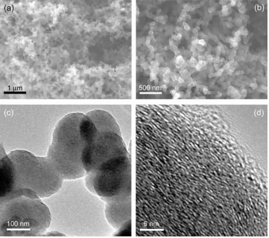
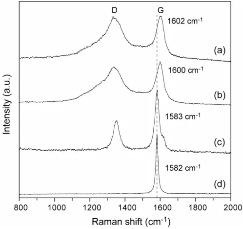
2 The Raman spectra of the colloidal carbons (Fig. 4(a)) and the hexane-derived nanoparticles (Fig. 4(b)) have shown the graphite-like G (E
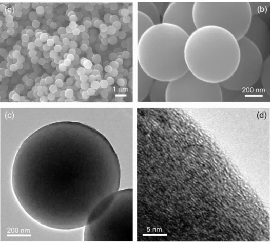
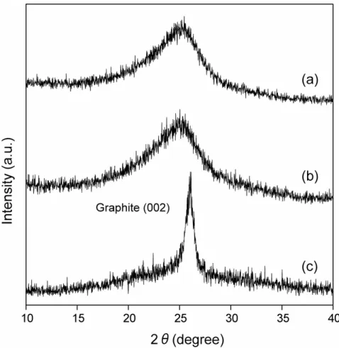
2g

The scanning electron microscopy (SEM) images (Fig. 1(a), (b)) show that the carbon derived from hexane at 400°C and 71 MPa is comprised of chain-like nanoparticles. The fringe pattern of the transmission electron microscopy (TEM) images indicates that the interlinked nanoparticles are coalescent with no definite boundary (Fig. 1(c)), and the microstructure is comprised of graphitic layers (Fig. 1(d)). In contrast, benzene has provided a fine spherical shape of not hollow but inner-filled colloidal carbons existing separately with a relatively uniform size, i.e., mean diameter: 720±112 (standard deviation) nm, population for calculation: 400 particles (Fig. 2(a)-(c)). More importantly, the graphitic layers seem to be less developed than that of the hexane-derived graphitic layers (Fig. 2(d)). The interlayer d

002

spacings calculated from the X-ray diffraction (XRD) peaks (Fig. 3 (a), (b)) were ca. 3.60 and 3.63 Å for the hexane- and the benzene-derived graphitic layers, respectively.

2

vibration of sp

2

carbon bonds) and the disorder-induced D peaks [10].

The G peaks of the colloidal carbons (1602 cm

-1

) and the nanoparticles (1600 cm

-1

) were located at the high

frequency side with reference to the G position (1582 cm

-1

) of highly oriented pyrolytic graphite (HOPG,

Fig. 4(d)). The high frequency shift is caused by a crystalline effect such as the structural change of

monocrystalline to polycrystalline graphite [10]. Therefore, the colloidal carbons and the nanoparticles

(3)

would be comprised of polycrystalline graphitic layers. Note that the relative intensity I

D

/I

G

(mean value in peak height [in peak area]: 0.875±0.062 [5.619±0.468] (90% confidence interval (CI)), degree of freedom:

Φ=13) of the D to the G peak of the colloidal carbons is larger than the I

D

/I

G

(mean value in peak height [in peak area]: 0.795±0.085 [4.544±0.287] (90% CI)], Φ=13) of the hexane-derived nanoparticles. The origin of the D peak is explained as the A

1g

breathing motions of aromatic rings existing in the edge sites of graphene sheets and their defects. Therefore, the more intense D peak indicates that the colloidal carbons would contain more graphene edge sites. Considering the meticulous fringe pattern of the TEM image, the colloidal carbons would be comprised of smaller graphene units (or aromatic clusters) than the hexane- derived graphene units.

The graphitization of the colloidal carbon reflects the smallness of the graphene units. The sharpening and small frequency shift of the G peak (Fig. 4(c)), the substantial decrease of the I

D

/I

G

(mean value in peak height [in peak area]: 0.557±0.037 [0.721±0.035] (90% CI), Φ=13) and the narrowing of the (002) peak (Fig. 3(c), d

002

= ca. 3.43 Å) reveal the more graphitized structure. The SEM and TEM images show that the graphitization is achieved with the spherical shape maintained, and the microstructure is comprised not of concentrically arranged layers [11, 12] but of ribbon-like layers with no particular direction (Fig. 5). The arbitrary direction of the graphitization would be attributed to the flexibility of rearrangement of the aromatic clusters originating from their smallness.

In conclusion, a limited use of H

2

O

2

in scH

2

O has successfully produced graphitic carbons from hydrocarbons at the low temperature of 400°C. The choice of hydrocarbons leads to morphological and microstructural variations. The application of the H

2

O

2

-promoted synthesis in scH

2

O to various organic compounds will give us potential opportunities to create unique microstructures and textures of carbon.

Acknowledgment

This work was carried out in TIT as part of Research for the Future Program of the Japan Society for the Promotion of Science. The authors acknowledge partial supports by the second stage Intellectual Cluster Project, which is funded by the Ministry of Education, Culture, Sports, Science and Technology of Japan.

References

[1] Dong G.L., Hüttinger K.J. Consideration of reaction mechanisms leading to pyrolytic carbon of different textures. Carbon 2002; 40: 2515-28.

[2] Gogotsi Y., Libera J.A., Yoshimura, M. Hydrothermal synthesis of multiwall carbon nanotubes. J Mater Res 2000; 15: 2591-4.

[3] Motiei M., Hacohen Y.R., Calderon-Moreno J., Gedanken A. Preparing carbon nanotubes and nested fullerenes from supercritical CO

2

by a chemical reaction. J Am Chem Soc 2001; 123: 8624-5.

[4] Lou Z., Chen C., Zhao D., Luo S., Li Z. Large-scale synthesis of carbon spheres by reduction of supercritical CO

2

with metallic calcium. Chem Phys Lett 2006; 421, 584-8.

[5] Gloyna E.F., Li L., McBrayer R.N. Engineering aspects of supercritical water oxidation. Water Sci Technol 1994; 30: 1-10.

[6] Gloyna E.F., Li L. Supercritical water oxidation research and development update. Environ Prog 1995; 14: 182-92.

[7] Baur S., Schmidt H., Krämer A., Gerber J. The destruction of industrial aqueous waste containing biocides in supercritical water-development of the SUWOX process for the technical application. J Supercrit Fluids 2005; 33: 149-57.

[8] Croiset E., Rice S. F., Hanush R. G. Hydrogen peroxide decomposition in supercritical water. AIChE J 1997; 43: 2343-52.

[9] Ferry J.L., Fox M.A. Effect of temperature on the reaction of HO· with benzene and pentahalogenated phenolate anions in subcritical and supercritical water. J Phys Chem A 1998; 102: 3705-10.

[10] Ferrari A.C., Robertson J. Interpretation of Raman spectra of disordered and amorphous carbon. Phys Rev B 2000; 61: 14095-107.

[11] Inagaki M. Discussion of the formation of nanometric texture in spherical carbon bodies. Carbon 1997; 35: 711-3.

[12] Yoshizawa N., Tanaike O., Hatori H., Yoshikawa K., Kondo A., Abe T. TEM and electron tomography studies of carbon nanospheres for lithium secondary batteries. Carbon 2006; 44: 2558-64.

3

(4)

4 and JEM-2100F instruments operated at acceleration voltages of 15 kV and 120 kV, respectively.

Fig. 1. SEM ((a), (b)) and TEM ((c), (d)) images of the hexane-derived carbon nanoparticles synthesized at

400°C and 71 MPa. All the SEM and TEM images shown in this communication were recorded on JEOL

JSM-7000F/IV

(5)

Fig. 2. SEM ((a), (b)) and TEM ((c), (d)) images of the benzene-derived colloidal carbons synthesized at 400°C and 48 MPa.

5

(6)

Fig. 3. The graphite (002) peaks observed in the XRD analysis of (a) the hexane-derived nanoparticles, (b) the benzene-derived colloidal carbons and (c) the colloidal carbons graphitized by the heat-treatment at 2300°C for 30 minutes under argon atmosphere. XRD instrument: Rigaku RINT 2200V/PC-SV diffractometer with a CuKα-source operated at 40 kV and 20 mA. Step size: 0.02º.

6

(7)

Fig. 4. Raman spectra of (a) the benzene-derived colloidal carbons, (b) the hexane-derived nanoparticles and (c) the colloidal carbons graphitized by the heat-treatment at 2300°C for 30 minutes under argon atmosphere. (d) HOPG for reference. Raman spectroscopy instrument: Kaiser Optical Systems HoloLab- 5000 apparatus (incident excitation: 532 nm of Nd:YAG laser).

7

(8)

Fig. 5. SEM ((a), (b)) and TEM ((c), (d)) images of the benzene-derived colloidal carbons graphitized at 2300°C for 30 minutes under argon atmosphere.

8

Fig. 1. SEM ((a), (b)) and TEM ((c), (d)) images of the hexane-derived carbon nanoparticles synthesized at  400°C and 71 MPa
Fig. 2. SEM ((a), (b)) and TEM ((c), (d)) images of the benzene-derived colloidal carbons synthesized at  400°C and 48 MPa
Fig. 3. The graphite (002) peaks observed in the XRD analysis of (a) the hexane-derived nanoparticles, (b)  the benzene-derived colloidal carbons and (c) the colloidal carbons graphitized by the heat-treatment at  2300°C for 30 minutes under argon atmosphe
Fig. 4. Raman spectra of (a) the benzene-derived colloidal carbons, (b) the hexane-derived nanoparticles  and (c) the colloidal carbons graphitized by the heat-treatment at 2300°C for 30 minutes under argon  atmosphere
+2

参照

関連したドキュメント

ABTS, 2,2'-azino-di(3-ethylbenzthiazoline-6-sulfonic acid ; ABTS •+ , ABTS cation radical; FRAP, ferric reducing ability of plasma; ORAC, oxygen radical trapping antioxidant

Although the holonomy gives infinitely many tight contact structures up to isotopy (fixing the boundary), this turns out to be a special feature of the nonrotative case. This

Second, the main parameters of the algorithm are extended and studied in this continuous framework: the study of particular trajectories is replaced by the study of

Figure 3 shows the graph of the solution to the optimal- ity system, showing propagation of CD4+ T cells, infected CD4+ T cells, reverse transcriptase inhibitor and a protease

The approach based on the strangeness index includes un- determined solution components but requires a number of constant rank conditions, whereas the approach based on

Complex formation is used as a unified approach to derive represen- tations and approximations of the functional response in predator prey relations, mating, and sexual

Greenberg and G.Stevens, p-adic L-functions and p-adic periods of modular forms, Invent.. Greenberg and G.Stevens, On the conjecture of Mazur, Tate and

The table displays the number of linear iterations needed for solving the two-dimensional Bingham problem for different mesh sizes and different values for ε (used as a parameter in