RILEM TC212-ACD: “Acoustic Emission and Related NDE Techniques for Crack Detection and Damage Evaluation in Concrete”- Recommendation 3
Test Method for Classification of Active Cracks in Concrete Structures by Acoustic Emission
1. Scope
Concrete Structures are known to be no longer maintenance-free. Consequently, a variety of inspection techniques are under development and going to be established. It is well known that acoustic emission (AE) technique is promising to test concrete structures for damage estimation. In this respect, a test method for classifying active cracks is proposed. For in-situ inspection, estimation of active cracks is of significant important. Due to damage evolution in reinforced concrete structures, AE events are observed under in-service conditions. Generally speaking, nucleation of shear cracks follows tensile cracks on an existing failure surface. Accordingly, for an early warning of crack nucleation, the classification of active cracks is in great demand.
2. Related Codes
The recommendation is referred to the following standards, of which the newest version is cited.
(1) European Norms (EN)
EN1330-9 Nondestructive testing -Terminology-Part 9: Terms used in AE testing EN 13554 Nondestructive testing-Acoustic emission-General principles
(2) American Society for Testing and Materials (ASTM) E1316 Standard Definitions of Terms relating to AE
E650 Standard Guide for Mounting Piezoelectric AE Sensors E750 Standard Practice for Characterizing AE Instrumentation
(3) American Society for Nondestructive Testing (ASNT) DGZfP-SE1 Nondestructive Testing: Acoustic Emission Terms DGZfP-SE3 Guide line for AE Characterization during AE Test
(4) French Association for Standards (AFNOR)
NF A09-350 Nondestructive Testing-Vocabulary used in Acoustic Emission
(5) European Working Group on Acoustic Emission (EWGAE)
EWGAE Codes for AE Examination: Code I-Location of Discrete Acoustic Events EWGAE Codes for AE Examination: Code IV-Definition of Terms in AE
(6) Japanese Society for Nondestructive Inspection (JSNDI)
NDIS 2421 Recommendation Practice for In Situ Monitoring AE of Concrete Structures by AE
3. Definition of Technical Terms
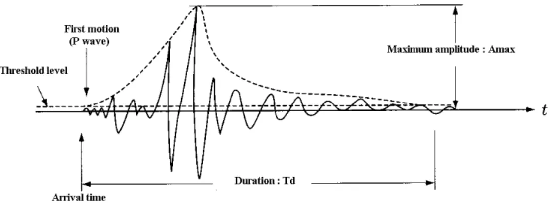
In addition to terms defined in RILEM recommendation,” Measurement Method for Acoustic Emission Signals in Concrete”, the following AE parameters shall be obtained by the measurement system. AE waveform parameters of the following: peak amplitude, rise time and duration time are illustrated in Fig. 1, along with the threshold level.
1) Peak amplitude: Largest amplitude value in a waveform.
2) Rise time: A duration time from the first arrival to the peak amplitude.
3) Duration time: Duration observed from the first arrival to the time when the amplitude decays up to the level lower than the threshold.
4) Counts: Normally, AE counts imply number of times the signal amplitude exceeds the threshold. They also are rigorously named ring-down counts.
5) External parameters: The measurement system shall be able to obtain time information along with AE parameters. In addition, such external parameters as load, strain and so forth are preferably recorded in the system.
Fig. 1 AE waveform parameters.
4. Measurement system 4.1 AE sensor
AE sensors shall be calibrated properly in advance of the measurement. AE sensors shall be sensitive enough to detect AE signals generated in a concrete structure, taking acoustic coupling into consideration. AE sensor shall be also robust enough against temperature change, moisture condition and mechanical vibrations in the environments.
For the parameter analysis, a broad-band sensor is recommended. But, resonance-type sensors are also available, in the case that their resonance frequencies are higher than 60 kHz in concrete.
4.2 System for signal analysis
The system of AE devices shall be specified, depending on the target. AE sensors are attached at proper locations to cover the target area. The internal noise of the amplifier shall be inherently low and less than 20 µV (26 dB for 0 dB = 1µV) as the peak voltage converted by input voltage. The amplifier shall be robust enough against the environmental conditions and be protected properly. The frequency range shall be determined prior to the measurement, taking into account the performance of AE sensor and the amplifier. The range from several kHz to several 100 kHz is recommended in concrete. The period of the measurement shall be prescribed, depending on propagation property of AE signals in the target structure.
5. Environmental noises
In advance to AE measurement, the noise level shall be estimated. Then, counteract against external noises, wind, rain, sunshine and so forth shall be conducted to decrease the noise level as low as possible. In the case that the noises have similar frequency contents, amplitudes to AE signals or sources of the noises are unknown, characteristics of the noises shall be estimated prior to the measurement. Based on this result, separation of AE signals from the noises shall be achieved. In this respect, the use of filters is applicable after determining the proper frequency range.
Sensitivity of AE channels shall be conducted routinely by employing the standard source. Variation within the channels shall be less than 3%.
6. Test Procedure
AE signals due to cracking shall be detected properly for the duration of the measurement. The test shall be conducted under loads which must not fundamentally make any critical damage on functions of the structure to detect and locate active cracks.
In advance to the test, attenuation properties of the target structure shall be estimated, by employing the standard source or the equivalent.
From AE parameters of the rise time and the peak amplitude in Fig. 1, the RA value defined as,
RA = the rise time / the peak amplitude (1) shall be calculated.
The averaged frequency Fa of each waveform shall be calculated from,
Average frequency (Fa) = AE ringdown counts/the duration time (2) where the definitions of AE ring-down counts and the duration time are given above.
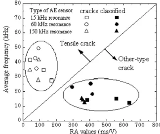
By applying these parameters, classification of cracks into tensile cracks and other-type cracks including shear cracks is performed as shown in Fig. 2. This shall be based on the moving average of more than 50 hits. It is noted that the RA values may vary depending on the threshold level. But, the figure shows that the selection of AE sensors does not provide much effect on the results as shown in the figure.
For plotting data, here, the ratio of the abscissa scale to the ordinate scale is set to 10.
But, it just means a suggestive value. A proper ratio shall be determined, depending materials and structures. It is recommended to set the ratio in advance to the classification of active cracks.
Fig. 2 Qualification of the damage by AE parameters.
7. Documents
Documents to report the results shall contain the following articles:
a) Date b) Test person
c) Devices
d) Measurement locations
e) Results of system inspection before and after the setup f) Results of analytical data before and after the setup