RILEM TC212-ACD: “Acoustic Emission and Related NDE Techniques for Crack Detection and Damage Evaluation in Concrete” – Recommendation 1
Measurement Method for Acoustic Emission Signals in Concrete
1. Scope
Concrete structures could deteriorate due to heavy traffic loads, fatigue, chemical reactions, unpredictable disasters, and poor workmanship, although concrete structures have long been referred to as maintenance-free. Eventually, retrofit and rehabilitation of the structures are in heavy demand all over the world. It results in the need for the development of advanced and effective inspection techniques prior to repair works. In this regard, acoustic emission (AE) techniques have been extensively studied in concrete engineering. These are inspection techniques by means of detecting elastic waves due to cracking and damage (micro-crack) accumulation, originally developed in materials science, seismology, and mechanical engineering.
Focussing on crack detection and damage evaluation, it is known that AE techniques are prospectively applicable to concrete and concrete structures. This is because AE events or phenomena are to be observed under in-service conditions. Here, a measurement method is standardized for detecting AE signals in concrete.
2. Related Codes
The recommendation is referred to the following standards established or published, of which the newest version shall be cited.
(1) European Norms (EN)
EN1330-9 Nondestructive testing -Terminology-Part 9: Terms used in AE testing EN 13554 Nondestructive testing-Acoustic emission-General principles
EN 13477-1 Nondestructive testing-Acoustic emission-Equipment characterization- Part 1: Equipment description
EN 13477-2 Nondestructive testing-Acoustic emission-Equipment characterization- Part 2: Verification of operating characteristics
(2) American Society for Testing and Materials (ASTM) E1316 Standard Definitions of Terms relating to AE
E650 Standard Guide for Mounting Piezoelectric AE Sensors E750 Standard Practice for Characterizing AE Instrumentation
E976 Standard Practice for Determining the Reproducibility of AE Sensor Response E1106 Standard Method for Primary Calibration of AE Sensors
(3) American Society for Nondestructive Testing (ASNT) DGZfP-SE1 Nondestructive Testing: Acoustic Emission Terms DGZfP-SE2 Guide line for AE Sensor Calibration
DGZfP-SE3 Guide line for AE Characterization during AE Test (4) French Association for Standards (AFNOR)
NF A09-350 Nondestructive Testing-Vocabulary used in Acoustic Emission (5) European Working Group on Acoustic Emission (EWGAE)
EWGAE Codes for AE Examination: Code I-Location of Discrete Acoustic Events EWGAE Codes for AE Examination: Code IV-Definition of Terms in AE
(6) Japanese Society for Nondestructive Inspection (JSNDI) NDIS 2110 Calibration of AE Sensors
NDIS 2421 Recommendation Practice for In Situ Monitoring AE of Concrete Structures by AE
3. Definitions of technical terms
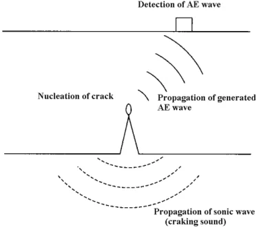
a) Acoustic emission (AE): transient elastic waves generated by the release of energy within a material. Microscopic fracture in concrete takes place with the release of stored strain energy as nucleating micro-cracks and generating elastic waves. These waves due to crack nucleation are referred to as AE waves, which propagate inside a material and are detected by an AE sensor as shown in Fig. 1.
Fig. 1 Detection of AE wave.
b) AE signal: The electrical signal detected at a sensor, which is converted through the detection of AE wave (elastic wave).
c) Burst emission: A description of the signal that has a rapid rise to peak and slower decay to the noise level. Burst-type AE signals are typically detected in concrete. In contrast, under plastic deformation in metal, emissions are observed continuously without the decay. This is normally named “continuous emission”.
d) Channel: One line of AE signal detected by AE sensor and processed by the other devises.
e) Hit: A hit is the term to indicate that a given AE channel has detected and processed one AE transient. Counting methods of AE signals are later described in the section 5 of ‘signal analysis and AE parameters’ .
f) Event: AE wave can be detected in the form of hits on one or more channels. One event is a group of AE hits received from a single source by two or more channels, of which spatial coordinates could be located.
g) Array: Spatial arrangement of AE sensors for spatially locating AE sources h) Attenuation: The observed loss of a signal as it travels through a medium.
i) Noises: Signals produced by causes other than AE phenomena. Elimination of noises is essential for effective detection of AE signals.
4. Measuring system
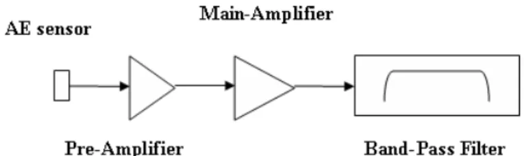
AE measuring system shall consist of the following devices with prescribed functions. A basic system is illustrated in Fig. 2, where only analog devices are shown.
Following this system, a digital signal-processor is usually equipped.
Fig. 2 AE measurement system.
4.1 Sensor
AE sensors shall be sensitive enough to detect AE signals generated in the target structure, taking acoustic coupling into consideration. They convert elastic waves (motions) on the surface of a material into electric signals, preferably, without any distortions. A resonance-type sensor is most sensitive around the resonant frequency, while a broad-band sensor has approximately flat response in the range but is less sensitive than the resonance-type. AE sensor shall be robust enough against temperature change, moisture condition and mechanical vibrations in the environments.
Sensitivity calibration of AE sensors shall be performed by employing the standard source. A simulated AE source due to pencil-lead break is defined in ASTM, ASNT, NDIS and others. This standard source is illustrated in Fig. 3, where a guide ring is recommended to be employed.
Fig. 3 Standard AE source.
4.2 Amplifier
Amplifiers normally consist of the pre-amplifier and the main amplifier as shown in Fig. 2. The pre-amplifier shall be located as close as possible to AE sensor. The internal noise of the amplifier shall be inherently low and less than 20 µV (26 dB for 0 dB = 1µV) as the peak voltage converted by input voltage. Here, the gain of the amplifier is given in dB (decibels), which means the ratio of the output voltage Vo to the input voltage Vi as,
Vi) (Vo log dB=20 10
The amplifier shall be robust enough against the environmental conditions and be protected properly.
4.3 Filter
The frequency range shall be determined prior to the measurement, taking into account the performance of AE sensors and the amplifiers. Selection of the frequency rage is closely related to elimination of noises. In concrete, the use of a band-pass filter between several kHz and several 100 kHz is recommended.
5. Signal analysis and AE parameters
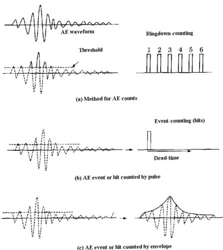
One waveform is to be counted as one AE event, while the cycles over the threshold level are named as AE ring-down counts (or simply “counts”). Here, the threshold is a preset voltage level, which has to be exceeded before one AE signal is detected and processed. Methods for AE counting are illustrated in Fig. 4. In the case of multi-channel observation, AE occurrence is monitored at each sensor location. At some sensors, AE signals may not be observed due to attenuation or undetectable propagation path. The number of the events which are counted at one of the channels corresponds to the number of AE hits defined above.
Fig. 4 AE counting methods.
In addition to AE count, AE hit and AE event, the following AE parameters shall be obtained by the measurement system.
1) Peak amplitude 2) AE energy 3) Rise time 4) Duration time
5) Arrival time differences in AE sensor array
6) External parameters: The measurement system shall be able to obtain time information along with AE parameters. In addition, such external parameters as load, strain and so forth are preferably recorded in the system.
The waveform parameters of arrival time, duration and peak amplitude are displayed in Fig. 5, showing the threshold level. The rise time means a duration from the arrival to the peak. There exist a variety of definitions on AE energy. In principle, AE energy corresponds to an area of the envelope of the waveform.
Fig. 5 AE waveform parameters.
6. Setup and Measurement 6.1 Sensor setup
AE sensors shall be calibrated properly in advance of the measurement. They are attached at proper locations to cover the target area. The period of the measurement shall be prescribed, depending on the following conditions:
a) Propagation property of AE signals in the target structure b) Stress distribution in the structure under inspection
6.2 Environmental noises
In advance to AE measurement, the noise level shall be estimated. Then, counteract against external noises, wind, rain, sunshine and so forth shall be conducted to decrease the noise level as low as possible. In the case that the noises have similar frequency contents, amplitudes to AE signals or sources of the noises are unknown, characteristics of the noises shall be estimated prior to the measurement. Based on this result, separation of AE signals from the noises shall be achieved. In this respect, the use of filters is applicable after determining the proper frequency range.
6.3 Measurement
In an existing structure, a measurement is normally conducted under loads which must not make a critical damage on functions of the structure to detect and locate active cracks. Based on the spatial area to be covered by AE sensors, those of proper frequency characteristics shall be selected. In advance to the test, attenuation properties of the target structure shall be estimated, by employing the standard source or the equivalent. Based on this information, sensor array shall be determined so as to keep the equivalent sensitivities in all the sensors. AE signals due to cracking shall be detected properly for the duration of the measurement. Concerning AE parameters detected, their trend, distribution, correlation, and locations are monitored. In addition, multi-channel observation provides to locate AE sources, by applying the location routine available.
6.4 System inspection
Sensitivity of AE channels shall be conducted routinely by employing the standard source. Variation within the channels shall be less than 3%.
6.5 Storage of data
The system shall be equipped with an enough memory to record the data measured.
It is preferable that all the data recorded are analyzed digitally by computer.
7. Documents
Documents to report the results shall contain the following articles:
a) Date b) Test person c) Devices
d) Measurement locations
e) Results of system inspection before and after the setup f) Results of analytical data before and after the setup