Parametrically Excited van der Pol Oscillators Coupled by a Resistor
Hironori Kumeno
Dept. of Electrical and Electronic Eng., Tokushima University,
Tokushima 770-8506, JAPAN Email: [email protected]
Yoshifumi Nishio
Dept. of Electrical and Electronic Eng., Tokushima University,
Tokushima 770-8506, JAPAN Email: [email protected]
Abstract— In this study, we investigate synchronization of parametrically excited van der Pol oscillators. By carrying out computer calculations for two or three subcircuits case, we confirm that various kinds of synchronization phenomena of chaos are observed. In the case of two subcircuits, we confirm that synchronization phenomena are related to phase difference of the functions corresponding to the parametric excitation. Then the two subcircuits are synchronized at the opposite-phase. In the case of three subcircuits, we confirm self-switching phenomenon of synchronization states when there is not phase difference of the functions corresponding to the parametric excitation. On the other hand, when there is phase difference, two of the three subcircuits are synchronized at the opposite-phase.
I. INTRODUCTION
Synchronization is one of the fundamental phenomena in nature and it can be described by nonlinear oscillators that has regular and chaotic states. Synchronization of van der Pol oscillator is one of synchronization of natural rhythm phenomena, and many researchers studied it. Parametric ex- citation circuit is one of resonant circuits, and it is important to investigate various nonlinear phenomena of the parametric excitation circuits for future engineering applications. In this study, we investigate synchronization of parametrically excited van der Pol oscillators.
II. CIRCUIT MODEL
The circuit model used in this study is shown in Fig 1.
In our system n same parametrically excitaed van der Pol oscillators are coupled by one resistorR. The circuit includes a time-varying inductor L whose characteristics are given as the following equation, and are shown as Fig. 1(b).
L=L0γ(t). (1)
γ(τ)is expressed in a rectangular wave as shown in Fig. 2, and its amplitude and angular frequency are termedαandω.
The v−icharacteristics of the nonlinear resistor are approx- imated by the following equation.
id =−g1vk+g3vk. (2) By changing the variables and the parameters,
t=p
L0Cτ, vk= rg1
g3xk, δ= rC
L0R, ik =
rg1
g3
rC
L0yk, ε=g1
rL0
C,
(3)
(a) Parametrically excited van der Pol oscillators coupled by a resistor.
(b) Time-varying inductor.
Fig. 1. Circuit model.
Fig. 2. Rectangular wave.
2007 IEEE Workshop on Nonlinear Circuit Networks NCN'07, Tokushima, Japan, Dec 7--8, 2007
- 46 -
the normalized circuit equations are given by the following equations.
dxk
dτ =ε(xk−x3k)−yk
dyk
dτ = 1
γ(τ)xk−δ Xn
j=1
yj.
(4)
Fig. 3. One-parameter bifurcation diagram for rectangular wave. Horizontal axis:x. Vertical axis:ε.α= 0.95andω= 1.50.
Figure 3 shows the bifurcation diagram observed from the isolated subcircuit. When parameter ε changes, periodic attractors, quasi-periodic attractors and chaotic attractors are confirmed from the isolated subcircuit. Figure 4 shows exam- ples of chaotic attractors and Poincar´e maps observed from the isolated subcircuit. We define the Poincar´e section as
“ωτ = 2nπ”.
(a)
(b)
Fig. 4. Examples of chaotic attractors and Poincar´e maps observed from each subcircuit,α= 0.95andω= 1.50. (a)ε= 1.0. (b)ε= 1.5.
III. TWO SUBCIRCUITS CASE
In this section, we consider the case of n = 2. Only two parametrically excited van der Pol oscillators are coupled by one resistor. First, fix ε = 1.50, α = 0.95, ω = 1.50 and δ = 0.80 and vary phase difference of the rectangular wave.
Two subcircuits generate chaos for these parameter values.
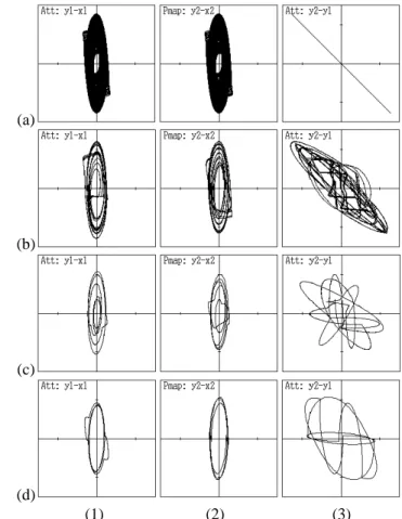
Figure 5 shows computer calculated results. As shown in (a)
(b)
(c)
(d)
(1) (2) (3)
Fig. 5. Attractors and phase differences.ε= 1.50,α= 0.95,ω= 1.50 andδ= 0.80. Phase difference of rectangular wave: (a)0, (b)π/20, (c)π/4 and (d)π. (1)x1versusy1. (2)x2versusy2. (3)y1versusy2.
Fig. 5(a), when there is not phase difference, two subcircuits are synchronized at the opposite-phase completely. However, as phase difference increases, two circuits become out of synchronization (see Figs. 5(b) and (c)).
Second, fixε= 1.35,α= 0.95,ω= 1.50andδ= 0.80and vary phase difference of the rectangular wave. Two subcircuits generate periodic attractor for there parameter values. Figure 6 shows computer calculated results. In the same way, when there is not phase difference, two subcircuits are synchronized at the opposite-phase completely as shown in Fig. 6(a). And as phase difference increases, two circuits become out of synchronization (see Figs. 6(b), (c) and (d)). Additionally, chaotic attractor is obtained as shown in Fig. 6(b). In spite of isolated subcircuit conditions, chaotic attractors generation or disappearance are obtained by phase difference.
IV. THREE SUBCIRCUITS CASE
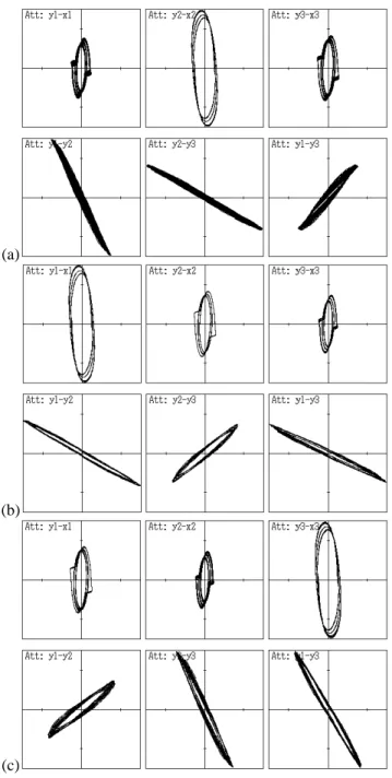
In this section, we consider the case of n = 3. Figure 7 shows computer calculated results for ε = 1.50, α = 0.95, ω = 1.50,δ = 0.80 and there is not phase difference of the rectangular wave. In this case, self-switching phenomenon of synchronizations is observed. As shown in Fig. 7(a), subcir- cuits 1 and 2 are synchronized at opposite-phase, subcircuits 1 and 3 are synchronized at opposite-phase. However, as time advances, pattern of synchronization changes. As shown in the
- 47 -
(a)
(b)
(c)
(d)
(1) (2) (3)
Fig. 6. Attractors and phase differences.ε= 1.35,α= 0.95,ω= 1.50 andδ= 0.80. Phase difference of rectangular wave: (a)0, (b)π/20, (c)π/4 and (d)π. (1)x1 versusy1. (2)x2 versusy2. (3)y1 versusy2.
Fig. 7(b), subcircuits 1 and 2 are synchronized at opposite- phase, subcircuits 2 and 3 are synchronized at opposite-phase.
Furthermore, as time passes subcircuits 1 and 3 are synchro- nized at opposite-phase, subcircuits 2 and 3 are synchronized at opposite-phase (see Fig. 7(c)). When the subcircuit param- eters are regarded as constant, switching speed is related to the coupling parameterδ. If the coupling parameterδis small, bonding force is weak. So switching speed is fast. As the cou- pling parameter δ increases, switching speed becomes slow.
Additionally, self-switching phenomenon of synchronizations is also confirmed when isolated subcircuits generate periodic attractors for ε = 1.35. However, when the parameter ε is small, self-switching phenomenon of synchronizations is not observed. A pair of subcircuits are synchronized at opposite- phase that are decided by initial values. Thus, generation of the self-switching phenomenon of synchronizations is related to the parameter ε, and its switching speed is related to the coupling parameter δ. By comparison of attractors generated from the isolated subcircuit, local amplitude of the attractor for ε = 1.5 is larger than it for ε =1.0. We believe that the generation of the self-swiching phenomenon is related to this change of the local amplitude.
Second, we consider the case that there is phase difference of the rectangular wave. Fix ε = 1.50, α= 0.95, ω = 1.50 and δ = 0.30, and shift phases of the rectangular wave of the subcircuits to2π/3 and4π/3. In this case, self-switching
(a)
(b)
(c)
Fig. 7. Attractors and phase differences.ε= 1.50,α= 0.95,ω= 1.50 andδ= 0.80.
phenomenon of synchronizations is not observed. Figure 8 shows that three different types of synchronization states.
These three synchronization states can be obtained by giving different pattern of phase shift of the rectangular wave. Two of the three subcircuits are synchronized at the opposite-phase.
A pair of synchronized subcircuits is decided by the sequence of phase shift of the rectangular wave.
V. CONCLUSIONS
In this study, we investigated synchronization of para- metrically excited vander Pol oscillators. By carrying out computer calculations for two or three subcircuits case, we confirmed that various kinds of synchronization phenomena of chaos were observed. In the case of two subcircuits, we
- 48 -
(a)
(b)
(c)
Fig. 8. Attractors, phase differences and time series.ε= 1.50,α= 0.95, ω= 1.50andδ= 0.30. Phase differences of rectangular wave are2π/3and 4π/3.
confirmed that synchronization phenomena are related to phase difference of the functions that corresponding to the para- metric excitation. Then the two subcircuits are synchronized at the opposite-phase. In the case of three subcircuits, just three coupling van der Pol oscillators are synchronized at the three-phase. However, three coupling parametric excited van der Pol oscillators generate self-switching phenomenon of synchronization states when there is not phase difference of the the functions corresponding to the parametric excitation.
On the other hand, when there is phase difference, two of the three subcircuits are synchronized at the opposite-phase.
ACKNOWLEDGMENT
This work was partly supported by Yazaki Memorial Foun- dation for Science and Technology.
REFERENCES
[1] C. Hayashi, “Nonlinear Oscillations in Physical Systems,” Chap. 11, McGraw-Hill, New York (1964).
[2] C. Hayashi, M. Abe, K. Oshima and H. Kawakami, “The method of mapping as applied to the solution for certain types of nonlinear differen- tial equations,” Ninth International Conference on Nonlinear Oscillations, Kiev (Aug.-Sept.1981).
[3] M. Inoue, “A Method of Analysis for the Bifurcation of the Almost Peri- odic Oscillation and the Generation of Chaos in a Parametric Excitation Circuit,” Trans. of IEICE, vol. J68-A, no. 7, pp. 621-626, 1985.