SUMMARY In this paper, we present the roles played by millimeter- waves in the realization of an Internet of Things (IoT) society. Millimeter- waves are becoming essential frequency resources, enabling ultra-high- speed wireless networks supporting massive data traffic and high-resolution sensor devices. Multiple antenna technologies such as phased arrays, sec- tor antennas, and MIMO signal processing are key technologies for putting these into practical use. In this paper, various examples of integration of multi-antenna systems are shown, as well as demonstration on 60 GHz- band millimeter-wave wireless access and 79 GHz-band high-resolution radar. We also propose applications to ITS for an IoT society, combining millimeter-wave wireless access and radar sensors, and discuss technical issues to be solved in the future.
key words: IoT, millimeter-wave, 5G, radar, phased array, MIMO
1. Introduction
With the spread of mobile devices such as smartphones, mo- bile data traffic has been increasing exponentially from year to year. Furthermore, with the progress towards an IoT so- ciety where everything communicates with each other, the amount of data traffic will increase even further. In view of this, the realization of 5th generation (5G) mobile net- works[1],[2], which will be a key communication network environment supporting the needs of an IoT society, is ea- gerly anticipated. In order to accommodate huge amount of data traffic, there have been increasing expectations for the effective utilization of the millimeter-wave bands[3].
Millimeter-waves are expected to be used for high- speed wireless communication, and in the beginning of the year 2000, a small prototype device[4]was actively devel- oped for that purpose. Ever since, standards for communi- cation in millimeter-wave bands have been developed and the momentum for practical use has been picking up. With the emergence of OFDM and MIMO technologies, which are technologies for improving frequency utilization effi- ciency, yet further potentials are made possible for speeding up data communication in order to fully maximize utiliza- tion of millimeter-waves. For 5G, the scarcity of the fre- quency resources is obvious. Therefore, in order to fulfil the system requirements, utilization of the millimeter-wave and terahertz is indispensable. Several frequency bands have been studied in the millimeter-wave band, between 24.5 and
Manuscript received March 27, 2017.
Manuscript revised June 16, 2017.
†The authors are with Panasonic Corporation, Yokohama-shi, 225–8539 Japan.
a) E-mail: [email protected] DOI: 10.1587/transele.E100.C.809
86 GHz. Among them, 7 to 9 GHz of bandwidth has been allocated as unlicensed band at frequencies around 60 GHz, thereby providing an excellent mean to achieve very high data rate above multi-gigabits. In addition, international standards targeting indoor short-range communication, such as IEEE 802.11ad/WiGig, having been developed[5] and put into practical use, are expected to be an important el- ement of 5G[6].
On the other hand, research and development of sensor applications utilizing millimeter-waves has also been pro- ceeding. A typical example application is a collision avoid- ance radar for automotive purposes, where a 76 GHz-band in-vehicle radar is put into practical use for collision avoid- ance or automatic cruise control (ACC)[7]. In order to fur- ther improve the sensor resolution, use of the 79 GHz band was also considered, with frequency allocation for the band of 77 GHz to 81 GHz subsequently completed in the World Radio Conference in 2015 (WRC-15)[8]. It is expected that the 79 GHz-band radar will be popular in the future. Re- search and development on the use of millimeter-wave ex- ceeding 100 GHz has also been made to further improve the sensor resolution[9]. One of the reasons for the ac- tive utilization of these millimeter-wave bands is that CMOS technology capable of large-scale integration has been real- ized[10].
In this paper, in Sect. 2, we first show the roles that fre- quency bands of millimeter-waves play in the future IoT era.
Section 3 shows the feasibility of millimeter-wave CMOS, demonstrating that it can be used to enable wireless ac- cess by introducing beamforming and sector antenna tech- nologies. In Sect. 4, we introduce an example of the re- alization of a high-resolution, three-dimensional scanning radar using MIMO technology. In Sect. 5, we propose vehicle-to-everything (V2X) applications for IoT combining millimeter-wave radio access technology and sensor tech- nology.
2. Evolution of IoT
Here we consider the role of millimeter-wave in IoT. Fig- ure 1 shows a conceptual diagram of IoT. In Fig. 1 (a), the data output from the sensor device is gathered in the cloud through the access network, gateway, and core network. The cloud analyzes data and gains an insight by artificial intel- ligence (AI) technology. Subsequently, it returns a control signal to the node terminal. The principle of IoT is to gener- Copyright c2017 The Institute of Electronics, Information and Communication Engineers
Fig. 1 Internet of Things (IoT) architectures (a) conventional IoT struc- ture and (b) evolved IoT structure with edge computing
ate added value in the flow of these data. As IoT evolves, the number of sensor devices increases tremendously, resulting in vast explosion of data traffic that the existing networks can no longer accommodate. For applications that analyze and collect data gathered from sensor devices without la- tency, such as automatic driving assistance system (ADAS), it is necessary to analyze the data and gain an insight with a processor located physically close to the sensor devices.
The area close to the sensor device is commonly called the
“edge”, giving rise to the term “edge computing”[11]to re- fer to data processing close to the sensor device, as shown in Fig. 1 (b). Since the “edge” exists in front of the cloud, it is also called “fog computing”[12]. In the evolved IoT, as shown in Fig. 1 (b), multiple local IoTs analyze data and gain insights at the edge close to the sensor devices. In addi- tion, the hierarchical structure connects data from the edge to the cloud through the core network.
By employing millimeter-wave band for the access net- work, it is possible to aggregate huge amount of sensor data at the edge and realize advanced processing with low la- tency. Furthermore, since the amount of data flowing in the core network can be filtered at the edge, the load on the core network can also be reduced.
Wireless transmission using millimeter-wave is weak against non-line-of-sight (NLOS). Nevertheless, high-speed transmission is still possible if the line-of-sight (LOS) en- vironment can be secured, allowing it to achieve real-time capability. In the following sections, millimeter-wave wire- less local area network (WLAN) as access network, and millimeter-wave radar as sensor devices will be described.
3. 60 GHz-band WLAN for Network Access
In the 60 GHz band, research and development has been ac- tively conducted for short-range wireless access, and the re- sulting IEEE 802.11ad/WiGig standard holds the status of
“de facto”. IEEE 802.11ad, also known as WiGig, was pub- lished in December 2012, and an interoperability certifica- tion program based on the standard was launched by Wi-Fi Alliance in October 2016[13]. IEEE 802.11ay is currently being developed as the next generation 60 GHz technology
Fig. 2 Analog beamforming architecture
which extends the IEEE 802.11ad standard in order to real- ize high speed of above 20 Gbps, high density support, and other features which are required in 5G[14].
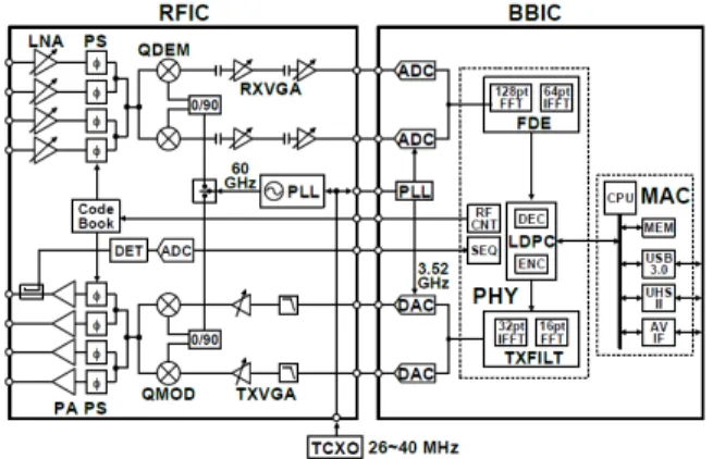
3.1 Analog Beamforming for Phased Array Antenna The authors have already developed a compact, low power consumption CMOS chipset targeted at mobile terminals such as smartphones[15]. The fabricated CMOS chipset employed various technologies, such as 1) Direct conversion architecture, 2) Frequency domain equalizer that compen- sates circuit frequency deviation and multipath fading, 3) Reduction of Fast Fourier Transform (FFT) size. Although it showed excellent performance as a chip set for mobile ter- minal from the viewpoint of low power consumption, per- formance as an access point (AP) was insufficient in view of the coverage area. Practical applications of 60 GHz-band millimeter-wave originally focused on point-to-point (P-P) link communication due to the narrow coverage of direc- tional antennas. For IoT applications, in order to communi- cate with multiple sensors, it is necessary to realize point-to- multi-point (P-MP) connection. Therefore, integration of a beamforming circuit for electronically controlling the direc- tivity of millimeter-waves has been realized. For beamform- ing, analog beamforming, which essentially uses a phased array antenna approach, was adopted. In addition, as a real- ization method of the phase shifter in the phased array an- tenna, a vector synthesis in the RF path[9] was adopted.
The reason for selecting the RF path is that the power con- sumption can be minimized. Figure 2 shows the architecture and Fig. 3 shows the chip micrograph. Figure 4 shows the measured phase shifter characteristics. As shown in Fig. 2, in order to realize beamforming, a phase shifter (PS) is in- serted in the receiver after the low nose amplifier (LNA) and in the transmitter before the power amplifier (PA). It adopts a vector phase shift synthesis circuit in the 60 GHz band.
The chip size is 3.2 mm×5.1 mm and is implemented with 40 nm CMOS. The antenna module size is 11 mm× 12 mm. 4-elements patch antennas in both transmission and reception realize a phased array antenna. Figure 4 shows the results of evaluating the characteristics of the vector phase shifter, which has 6 bits resolution both in I and Q channels.
Fig. 3 Fabricated 60 GHz RF chip with analog beamforming in 40 nm CMOS
Fig. 4 Measured phase-shifter characteristics
Fig. 5 Fabricated IEEE 802.11ad/WiGig access point (AP) block dia- gram
64×64 ways of amplitude and phase control were made possible as shown in the left figure of Fig. 4. Result of se- lecting a point which becomes a unit circle is shown in the right figure of Fig. 4.
PS with an angular resolution of 5◦was made possible.
Since 360◦can be divided into 128 points, ideally a resolu- tion of less than 2.8◦can be realized. However, degradation due to circuit imperfection resulted in resolution of about 5◦. By designing the 3-dB beamwidth of the patch antenna to 120◦, a coverage area of 120◦can be realized using a sin- gle phased array.
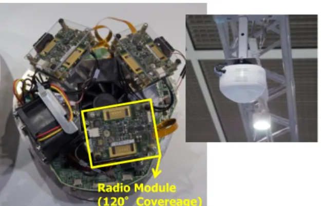
3.2 W-LAN System with 3-Sector Antennas
By having a WiGig module covering 120◦and defining that as one sector, a 360◦ area coverage can be realized using three such sectors. Figure 5 shows a block diagram of a WiGig AP that is based on multiple WiGig modules. A fab-
Fig. 6 Fabricated IEEE 802.11ad/WiGig AP
Fig. 7 Contents delivering system by WiGig AP with contents server controlled by 2.4/5 GHz AP
ricated WiGig AP is shown in Fig. 6. A high-speed content delivering system using the WiGig AP has been developed as shown in Fig. 7[16]. It consists of multiple WiGig APs, an AP controller (APC) and a legacy 2.4 or 5 GHz WLAN AP. All devices are centralized by a network switch and contents server. The APC manages frequency resources of WiGig APs, such as frequency channels and sector ID, to enable seamless handover. The 2.4 or 5 GHz AP can sup- port the WiGig APs’ coverage. It enables heterogeneous network (HetNet) to support mobility. In order to enable downloading of large size contents instantly from a cloud, contents server plays a significant role to shorten the system latency. It can be considered as an “edge” cloud. The above- mentioned system showed that the 60 GHz millimeter-wave band is sufficient to provide radio access networks with multi-gigabits capability.
4. 79 GHz Radars for Mobility Sensors
Millimeter-wave can also be applied as high-resolution radars because of their broadband frequency resources. Due to the nature of radio waves, they are excellent for object de- tection even in environments that are difficult to detect with visible light cameras, such as darkness, fog and dust. IoT applications based on such radars are expected in the mobil- ity field such as for automobiles.
Fig. 8 Block diagram of phased array antenna for 79 GHz Radar Trans- mitter
Fig. 9 Fabricated 79 GHz Radar front-end module
4.1 79 GHz Radar System Integration in CMOS
Collision avoidance radar in the 76 GHz band has already been put to practical use for automotive applications. Prac- tical applications of the 79 GHz band for a higher-resolution radar capable of utilizing broad frequency band, is under de- velopment. In the conventional millimeter-wave radar, the viewing area is narrow due to the narrow range of the direc- tional antenna. To address this, the use of the phased array antenna introduced in Sect. 3 can be applied here as an ef- fective mean to realize a wide viewing angle.
In order to realize a CMOS front-end for 79 GHz-band radar, an optimum phase shift circuit was researched[17].
In Sect. 3, a phase shifter is inserted in the RF path, but for radar, it is necessary to suppress the side lobe of the antenna.
This is because unwanted signals from the side lobe direc- tion can cause detection errors. In order to suppress the side lobe, a phase shifter was inserted into the baseband instead of the RF because accuracy in angular resolution is neces- sary.
Figure 8 shows a block diagram, and Fig. 9 shows a photo of the module with a CMOS chip mounted. The base- band phase shifter (BB-PS) is inserted after dividing the baseband radar pulse signal into 8 branches. Each signal is up-converted to the 79 GHz band by a mixer and then fed to each antenna. A power detector at power amplifier (PA) output for correcting the amplitude error between the 8
Fig. 10 Measured baseband phase shifter (BB-PS) characteristics
Fig. 11 Usage scenario of 79 GHz-band infrastructure Radar
branches is inserted in each branch. The fabricated module with 8 branch transmitters (TX) and 4 branch receivers (RX) is 40 mm×60 mm.
Figure 10 shows the measured BB-PS characteristics.
The BB-PS has resolution of 6 bits for each of the I and Q channels. As shown in Fig. 10 (a), it can be set to 64×64 points of phase and amplitude. Figure 10 (b) is the result of setting the bit condition to become a circle with amplitude 1.
The BB-PS achieved a performance of less than 2◦an- gle resolution, which is 2.5 times higher than a 60 GHz-band phased array with an RF PS.
4.2 Infrastructure Radar System for Pedestrian Safety The 79 GHz-band radar with high resolution and wide view- ing angle is expected to be utilized as infrastructure radar for preventing pedestrian accidents at intersections with poor visibility[18]. Figure 11 shows the usage scenario at the in- tersection. There are still many cases where pedestrians are injured in traffic accidents at intersections with poor visibil- ity. Since the developed 79 GHz radar, shown in Sect. 4.1, has a higher angular resolution, it can detect a pedestrian and a vehicle as separate objects even in an environment, such as at an intersection, where they both coexist. As it is possible to separate and detect pedestrians at intersections, the “Infrastructure Radar System” aims to prevent accidents by notifying this data to the driver.
Figure 12 shows a photograph of a radar prototype in- stalled close to the traffic signal. Figure 13 shows a cross section of the installation conditions. It was designed such that the radar device is tilted downward by 8◦ from the
Fig. 12 Experimental Radar setup at a crossing
Fig. 13 Cross-sectional view of infrastructure Radar setup
Table 1 Measured detected range for various types of vehicles
height of installation at 4 m and to detect vehicles in the range of 15 to 75 m. Pedestrians can be detected in the range of 20 to 40 m.
Table 1 shows the results of evaluation on the test course. Among the four models used in the experiment, since the sedan car has the lowest reflectance, the detectable distance is the narrowest. Nevertheless, the target distance of 15 to 75 m could still be achieved. Next, as shown in Fig. 13, the detection rate of pedestrians on the crosswalk di- agonally opposite to the radar was evaluated. For the pedes- trian on the pedestrian crossing, the detection rate was high, between 99.8 to 99.9%.
4.3 3D-MIMO Radar System[19]
The infrastructure radar shown in Sect. 4.2 has resolution in the distance direction and angle resolution in the hori- zontal direction, thus, can be termed as a radar with two dimensional (2D) scanning. If the angle resolution in the vertical direction is added, information on the height of the target can be obtained, thereby enabling more accurate de- tections. In order to obtain angular resolution in the vertical
Fig. 14 Top view of crossing
Table 2 Measured detect probability of pedestrian
Fig. 15 Virtual antenna array, of (a) conventional and (b) proposed un- equal spacing array
direction, it is necessary to arrange a plurality of antennas in the vertical direction in addition to the horizontal direc- tion. This means that a very large antenna array is required.
For this reason, techniques for virtually increasing the num- ber of antennas, without increasing the number of physical antennas, by MIMO signal processing have been studied.
Figure 15 (a) shows a virtual array antenna using conven- tional MIMO radar. Virtually 4×4, equal to 16 arrays, can be realized by 4 transmit and 4 receive arrays. As shown in Fig. 15 (b), by allocating antenna elements at unequal inter- vals, it is possible to enlarge the virtual array by interpola- tion techniques. Virtually, the realized performance is close to a 36 elements array of 6×6.
Figure 16 shows the block diagram of the MIMO radar, and Fig. 17 shows the fabricated MIMO radar module and prototype. The fabricated MIMO radar consists of the TX 4 branches (Nt=4) and the RX 4 branches (Nr=4). In order to perform MIMO processing in time division, switch (SW) is inserted for both TX and RX, and each TX branch and
Fig. 16 MIMO Radar block diagram
Fig. 17 Fabricated MIMO Radar module and prototype
each coherent integration in the reception (RX) are selected at each timing.
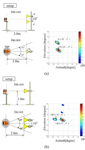
Using this MIMO radar, separation performance in the horizontal direction and vertical direction was realized. Fig- ure 18 (a) shows the evaluation result for the case that two standard corner reflectors (CRs) are placed in the vertical direction, and Fig. 18 (b) shows a similar case for the hori- zontal direction. “Setup” shows initial setting. Figure 18 (a) right figure shows measured results at−10◦offset in the az- imuth, and+5◦and−5◦offset in the elevation, respectively.
Similarly, Fig. 18 (b) shows the measured results at 0◦ off- set in the elevation, and 15◦and−5◦ offset in the azimuth, respectively.
It was confirmed that each of two objects can be sep- arated and detected. However, an error of 2 to 3◦ occurs in both the azimuth and the elevation direction, which is a future research topic.
5. V2X Applications Using mmW in Future IoT In order to realize ADAS and autonomous driving, it is nec- essary to utilize various data. Moreover, if autonomous driving is realized, the in-vehicle comfort level must be en- hanced. In the future, the data collected by in-vehicle de- vices is expected to become huge. The data collected by a roadside unit (RSU) also becomes more advanced, and so the high speed performance provided by the 60 GHz band, as described in Sect. 3, is very attractive.
In Fig. 19, we propose example applications for 60 GHz-band wireless access in the ITS field. Figure 19 (a) is an example illustrating content download from a RSU.
Fig. 18 Measured MIMO Radar for two obstacles for (a) vertical scan and (b) horizontal scan
Fig. 19 V2X Applications by mmW as future ITS; (a) instant 3D-map delivery, (b) driving recorder data uploading and (c) multi-hop video data sharing in platooning
It is effective for delivery of 3D-maps necessary for au- tonomous driving. Figure 19 (b) is an example illustrating contents uploading from an in-vehicle device. It is conceiv-
able to collect accumulated data from driving recorder and use it for operation management. Figure 19 (c) shows an ex- ample of sharing data between vehicles during platooning.
Because of the narrow beam nature of millimeter-waves, it is possible to communicate while suppressing interference from surroundings.
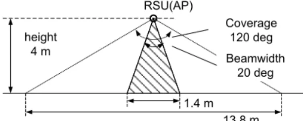
Figure 20 shows a basic cell design example based on a IEEE 802.11ad/WiGig AP. When the AP with a coverage beam angle of 120 degrees is installed at a height of 4 m, the area diameter becomes 13.8 m. Assuming that the antenna beam angle is 20 degrees, the area diameter covered by one antenna beam is 1.4 m. Assuming a travelling velocity of 100 km/h, it takes 49 ms to move 1.4 m. In other words, by scheduling the beamforming at least once every 49 ms, a vehicle moving at 100 km/h can be tracked continuously.
According to the IEEE 802.11ad/WiGig standard, it is possible to control the beam in every beacon interval.
The standard does not define the beacon interval time, al- though it is typically implemented to about 100 ms. In other words, by designing the implementation of the beacon inter- val, it can be said that even with the IEEE 802.11ad/WiGig standard, it is possible to upload and download mass data content in the context of high-speed mobility. In order to cope with high-speed mobility exceeding 100 km/h, it may be necessary to consider further design for existing pro- tocol. Furthermore, HetNet, which integrates millimeter- waves and microwaves, can be employed to realize excellent V2X that achieves both high speed and high reliability.
6. Conclusion
We have discussed the role of millimeter-waves in the fu- ture evolving IoT society. In IoT, edge processing which performs data processing near the sensor becomes impor- tant in applications requiring high speed and low latency such as ITS. Millimeter-waves will play a major role as a transmission path connecting sensors and edge processing.
In addition, as the edge processing environment becomes vi- able, sensors are becoming more sophisticated, and the roles of millimeter-waves as high resolution sensors will also become more prominent. In employing these millimeter- waves, multi-antenna technologies such as phased arrays, utilization of sector antennas, MIMO signal processing and the like are very important. In 5G, it is also important to utilize microwave technology to compensate for the nature of millimeter-waves, such as to enhance the coverage area of WLAN AP, and to support high-speed mobility for V2X
nications, Japan.
References
[1] ARIB 2020 and Beyond Ad Hoc Group White Paper, “Mobile com- munications systems for 2020 and beyond,” v1.0.0, Oct. 2014.
[2] C. Dehos, J.L. Gonz´alez, A.D. Domenico, D. Kt´enas, and L.
Dussopt, “Millimeter-wave access and backhauling: The solution to the exponential data traffic increase in 5G mobile communica- tions systems?,” IEEE Commun. Mag., vol.52, no.9, pp.88–95, Sept.
2014.
[3] K. Sakaguchi, E.M. Mohamed, H. Kusano, M. Mizukami, S.
Miyamoto, R.E. Rezagah, K. Takinami, K. Takahashi, N. Shirakata, H. Peng, T. Yamamoto, and S. Namba, “Millimeter-wave wireless LAN and its extension toward 5G heterogeneous networks,” IEICE Trans. Commun., vol.E98-B, no.10, pp.1932–1948, Oct. 2015.
[4] K. Takahashi, S. Fujita, M. Inoue, G. Wu, and H. Yabuki, “A com- pact Ka-band 156 Mbps transceiver for a wireless LAN system us- ing PTFE/FR-4 laminated MCMs,” 2002 IEEE MTT-S International Symp. Dig., pp.787–780, June 2002.
[5] IEEE 802.11ad, “Part 11: Wireless LAN medium access control (MAC) and physical layer (PHY) specifications, Amendment 3: En- hancements for very high throughput in the 60 GHz band,” Dec.
2012.
[6] S. Okasaka and K. Takinami, “5G heterogeneous mobile networks utilizing millimeter-wave,” Proc. SmartCom2016, IEICE Tech.
Rep., vol.116, no.29, SR2016-14, pp.51–53, May 2016.
[7] J. Wenger, “Automotive radar - Status and perspective,” IEEE Compound Semiconductor Integrated Circuit Symposium, 2005.
CSIC2005 Digest, pp.21–24, Oct. 2005.
[8] K. Nitta, “Overview report of WRC-15 results,” in Japanese, Journal of the ITU Associate in Japan, vol.46, no.5, pp.7–12, July 2016.
[9] J. Sato, K. Takinami, and K. Takahashi, “Millimeter wave CMOS integrated circuit for multi-gigabit communication and radar appli- cations,” 2015 IEEE International Symposium on Radio-Frequency Integration Technology (RFIT), pp.49–51, 2015.
[10] C. Doan, S. Emami, A.M. Niknejad, and R.W. Brodersen, “Design of CMOS for 60 GHz applications,” in ISSCC Digest of Technical Papers, 2004, pp.440–538, Feb. 2004.
[11] ETSI ISG, “Mobile-Edge Computing — A Key Technology To- wards 5G,” White Paper, no.11, pp.1–16, Sept. 2015.
[12] CISCO Whitepaper, “CISCO Visual Networking Index: Global Mo- bile Data Traffic Forecast Update, 2016-2021,” Feb. 2017.
[13] “Wi-Fi CERTIFIED WiGig,”
[online] http://www.wi-fi.org/discover-wi-fi/wi-fi-certified-wigig [14] Carlos Cordeiro, “Specification Framework for TGay,” IEEE802.11-
15/0135r9, Dec. 2016.
[15] N. Saito, T. Tsukizawa, N. Shirakata, T. Morita, K. Tanaka, J.
Sato, Y. Morishita, M. Kanemaru, R. Kitamura, T. Shima, T.
Nakatani, K. Miyanaga, T. Urushihara, H. Yoshikawa, T. Sakamoto, H. Motozuka, Y. Shirakawa, N. Yosoku, A. Yamamoto, R. Shiozaki, and K. Takinami, “A fully integrated 60-GHz CMOS transceiver chipset based on WiGig/IEEE 802.11ad with built-in self calibra- tion for mobile usage,” IEEE J. Solid-State Circuits, vol.48, no.12, pp.3146–3159, Dec. 2013.
[16] “Panasonic and Narita International Airport Announce World’s First
[19] T. Kishigami, H. Yomo, A. Matsuoka, and J. Sato, “Millimeter-wave MIMO radar system using L-shaped Tx and Rx arrays,” Proceedings of the 13th European Radar Conf., pp.29–32, Oct. 2016.
Kazuaki Takahashi received the B.E.
and M.E. degrees in electrical and computer engineering, and the Ph.D. degree in electri- cal engineering from Yokohama National Uni- versity, Yokohama, Japan, in 1986, 1988 and 2006, respectively. In 1988, he joined the To- kyo Research Laboratory, Matsushita Electric Industrial Co. Ltd., Kawasaki Japan, where he was engaged in research and development of monolithic microwave ICs, millimeter-wave ICs based on Si and GaAs for mobile communica- tion equipment. His current research interests include the development of short-range multi-gigabit wireless system and high resolution radar system in millimeter-wave and terahertz bands, and low-power radio systems for IoT systems. He is a chair of “Millimeter-wave Working Group (mmW- WG) of ITS forum, Japan, which is aiming to develop a radio standard of 79 GHz-band high resolution radar. He is also working on developing wireless standards in IEEE802.11 and Wi-Fi Alliance. Dr. Takahashi is a member of the IEEE.
Hidekuni Yomo received the B.E. de- gree in electrical engineering and the M.E. de- gree from the Tokyo University of Science, in 1995 and 1997, respectively. In 1997, he joined the Mobile Communication Research Labora- tory, Matsushita Research Institute Tokyo, Inc., as a Research Engineer. Since 2012, he has been involved in the development of millimeter- wave radar systems with Panasonic Corporation.
His research interests include radar digital sig- nal processing and wireless communication. He was a recipient of the Asia–Pacific Microwave Conference Prize in 2014.
Takashi Matsuoka received the B.E. de- gree in electric engineering from Waseda Uni- versity in 1989. He received the Ph.D. degree in information and communication engineering from the University of Tokyo in 2001. He joined Matsushita Electric Industrial Co., Ltd., Japan, in 1989. Now he is with Panasonic Corporation.
He has been engaged in research and develop- ment on digital radio communications and sen- sor systems.
munication and radar applications.
Yoichi Nakagawa received the B.S.
and M.S. degrees in electric engineering from Waseda University, Tokyo, in 1994 and 1996, respectively. From 1996 to 2001, he was with Matsushita Research Institute Tokyo, Inc. Since 2001, he has been with Matsushita Electric In- dustrial (Panasonic), Co., Ltd., where he has been engaged in research on array signal pro- cessing, mobile antenna and propagation chan- nel model. He is currently engaged in research on millimeter-wave radar and ITS related com- munication system.
Makoto Yasugi received the B.S. and M.S. degree in informatics from Kyoto Univer- sity in 1999 and 2001. He has been with Mat- sushita Electric Industrial Co. Ltd. (presently Panasonic) since 2001. He currently works on development of infrastructure sensor system for safe mobility using our millimeter-wave radar and other sensor devices.
Masataka Irie received the B.E. and M.E.
degrees in electrical engineering from Univer- sity of Electro-Communications, Tokyo, Japan in 1998 and 2000 respectively. He joined Pana- sonic Corporation, (former Matsushita Electric Industrial Co., Ltd.), Japan in 2000, where he worked on medium access controlling for wire- less LAN systems and wireless interface sys- tems. Currently he is involved in research and development of wireless communications.
Naganori Shirakata received the B.E. and M.E. degrees in electronics engineering from Kyoto Institute of Technology, Japan in 1993 and 1995 respectively. He joined Panasonic Corporation, (former Matsushita Electric Indus- trial Co., Ltd.), Osaka in 1995, where he worked on baseband signal processing of OFDM and MIMO for WLANs. From 2008 to 2010, He worked on ultra-low power radio and WBAN systems. From 2010 to 2013, he worked on the development of the PHY system and circuit de- sign for millimeter-wave transceiver. He currently leads the development of the system design for millimeter-wave access point and network. He is a member of IEEE.
was a visiting scholar at the University of Cal- ifornia, Los Angeles (UCLA), where he was involved in the architecture and circuit design of the high efficiency CMOS power amplifier. In 2006, he joined Panasonic Silicon Valley Lab, Cupertino, CA, where he worked on high efficiency transmitters and low phase-noise digital PLLs. In 2010, he relocated to Japan and currently leads millimeter-wave system develop- ment. Dr. Takinami is a co-recipient of the best paper award at the 2012 Asia-Pacific Microwave Conference, the best invited paper award from IEICE Electronics Society in 2015 and the Electrical Science and Engi- neering Promotion Awards (the OHM Technology Award) in 2015. He was a member of the ISSCC Technical Program Committee from 2012 to 2014.