PAPER
Insertion/Deletion/Substitution Error Correction by a Modified Successive Cancellation Decoding of Polar Code ∗
Hikari KOREMURA†,Nonmember andHaruhiko KANEKO†a),Member
SUMMARY This paper presents a successive cancellation (SC) decod- ing of polar codes modified for insertion/deletion/substitution (IDS) error channels, in which insertions and deletions are described by drift values.
The recursive calculation of the original SC decoding is modified to include the drift values as stochastic variables. The computational complexity of the modified SC decoding isO(D3)with respect to the maximum drift valueD, andO(NlogN)with respect to the code lengthN. The symmet- ric capacity of polar bit channel is estimated by computer simulations, and frozen bits are determined according to the estimated symmetric capacity.
Simulation results show that the decoded error rate of polar code with the modified SC list decoding is lower than that of existing IDS error correction codes, such as marker-based code and spatially-coupled code.
key words: insertion error, deletion error, synchronization error, polar code, successive cancellation decoding, list decoding
1. Introduction
Synchronization errors will be a major obstacle to improve the reliability of some types of future high-density memory and storage devices, such as, bit-patterned media record- ing[1], racetrack memory[2],[3], and DNA archival stor- age[4]. Hence, it is expected that error control codes ca- pable of correcting synchronization errors will be crucial to improve the reliability of these devices. Channels with synchronization errors are usually modeled by insertion/de- letion/substitution (IDS) channel, and several classes of IDS error correcting codes were proposed. For example, codes with the bounded distance decoding were designed based on a constraint on weighted sum of codeword bits, such as, single IDS error correcting code[5], multiple IDS error cor- recting code[6], and non-binary single IDS error correcting code [7]. Another strategy for IDS error correction is to employ the concatenated coding, where the outer code is a random error correcting code (e.g., LDPC code), and the inner code controls prior probabilities of channel input bits, such as watermark embedding[8]and marker insertion[9].
Also, it was shown that spatially-coupled codes can correct IDS errors without using the inner coding[10].
Arıkan proposed polar coding with successive cancel- lation (SC) decoding[11], which can achieve the symmetric capacity of any binary-input memoryless channel with the computational complexity ofO(NlogN), where N =2nis
Manuscript received June 3, 2019.
Manuscript revised November 13, 2019.
†The authors are with the School of Computing, Tokyo Institute of Technology, Tokyo, 152-8552 Japan.
∗Some parts of this paper were presented at the 2019 IEEE International Symposium on Information Theory (ISIT 2019).
a) E-mail: [email protected]
DOI: 10.1587/transfun.2019EAP1079
the code length. Şaşoğlu et al. proved that the polar code can achieve the capacity of any discrete memoryless chan- nel [12]. To improve the performance of polar code with finite code length, Tal and Vardy presented SC list (SCL) decoding with cyclic redundancy check (CRC) [13]. For correction of synchronization errors using the polar code, Thomas et al. presented a polar coding for channels with erasures and deletions[14], where the coding mainly deals with single deletion errors. Tian et al. proposed an SC de- coding of polar code for channels withddeletions[15], and they proved that this coding achieves the symmetric capacity.
Existing IDS channels often assume that insertions and deletions occur probabilistically [3], [4], [8]–[10], as op- posed to the deletion model in[15]. That is, received word may have multiple insertion and deletion errors simultane- ously, and thus the numbers of insertions and deletions can- not be determined uniquely from the received word length N0. Hence, extension of thed-deletion correction polar cod- ing [15]to the multiple insertion/deletion error correction coding will not be straightforward. From this, we present an SC decoding of polar codes for IDS channels in which inser- tion, deletion, and substitution errors occur with probability pi,pd,andps, respectively, under a constraint on maximum drift between transmitted and received bits. This paper em- ploys an IDS channel model expressed by a sequence of drift values, which is suitable for deriving a modified recursive computation in the SC decoding. That is, the appropri- ate combination of the IDS channel model and recursive computation enables a natural extension of the existing SC decoding to IDS error correction. Simulation results show that the presented SC decoding has lower decoded error rates compared to the existing marker-based code and spatially- coupled code.
The rest of this paper is organized as follows. Section 2 describes notations used in this paper. Section 3 defines IDS channel model. Section 4 presents a polar coding with modified SC decoding for IDS channel. Section 5 shows simulation results, and Sect. 6 concludes this paper.
2. Notations
This paper uses the following notations. Finite subsets of integers are defined asZM ={0,1, . . . ,M−1}andB=Z2 = {0,1}. The inversion of bitxis denoted asx=x⊕1, where
⊕is the XOR operator, andx,x ∈ B. For a binary vector a = (a0,a1, . . . ,aN−1) ∈BN of lengthN, sub-vectoraij is defined as
Copyright © 2020 The Institute of Electronics, Information and Communication Engineers
b=(b0,b1, . . . ,bN−1)∈B , XOR ofaandbis defined as a⊕b =(a0⊕b0,a1⊕b1, . . . ,aN−1⊕bN−1).
Probability that a random variableX takes a valuexis sim- ply denoted as p(x) , Pr(X = x). Conditional and joint probabilities are denoted similarly, that is,p(x|y),Pr(X = x|Y =y)andp(x, y),Pr(X =x,Y =y).
3. Channel Model
Letxandybe transmitted and received words, respectively, where the words are expressed by binary vectors as
x=x0N−1=(x0,x1, . . . ,xN−1)∈BN and y=y0N0−1=(y0, y1, . . . , yN0−1)∈BN
0.
Let pi,pd, and ps be insertion, deletion, and substitution error probabilities, respectively. And letDbe the maximum absolute value of drift betweenxandy. Insertion/deletion errors betweenxandyare expressed by a drift vector
d=(d0,d1, . . . ,dN−1,dN)∈ DN+1,
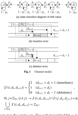
whereD ={−D, . . . ,−1,0,1, . . . ,D}is the set of drift val- ues. We assume that the drift vector is determined by Markov process with the following state transition probabilities:
p(di+1|di)=
pi ((di+1=di+1)∧(di ,D)) pd ((di+1=di−1)∧(di ,−D)) 1−pi−pd ((di+1=di)∧(−D<di <D)) 1−pi ((di+1=di)∧(di =−D)) 1−pd ((di+1=di)∧(di =D))
0 (otherwise)
, (1)
where the initial drift value isd0 = 0. Figure 1 (a) shows the state transition diagram ofdi. From this definition, d satisfies−1≤di+1−di ≤1 for alli ∈ZN. LetI(i;di,di+1) be a set of indices in received wordy0N0−1corresponding to thei-th transmitted bitxi, that is,
I(i;di,di+1)={i0|i+di ≤i0<(i+1)+di+1} ⊂ZN0, where N0 = N +dN. The following relations hold for I(i;di,di+1):
Fig. 1 Channel model.
|I(i;di,di+1)|=
2 (di+1=di+1(insertion)) 1 (di+1=di)
0 (di+1=di−1(deletion)) ,
∀i,j∈ZN,(i,j)→ I(i;di,di+1)∩I(j;dj,dj+1)=φ, [
i∈ZN
I(i;di,di+1)=ZN0,
whereφ is the empty set. For each transmitted bit xi(i ∈ ZN), received bit values are determined according to
p(yi0|xi)=
1−ps (yi0 =xi) ps (yi0 =xi),
wherei0 ∈ I(i;di,di+1). Figure 1 (b) and (c) illustrate the relations between drift valuedi and insertion/deletion error.
4. Polar Code for IDS Channel
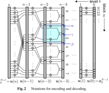
LetN=2nbe the code length of polar code. LetAandAc be sets of information and frozen bits, respectively, where A ∪ Ac =ZN andA ∩ Ac =φ. The positions of frozen bits are determined based on a simulation based estimation described in Sect. 4.3. It is assumed that the value of frozen bit is zero, while effect of frozen bit values on the decoded error rate will be examined by simulation in Sect. 5.2. En- coding and decoding usen+1 intermediate binary vectors, u(n), u(n−1), . . . , u(0) ∈ BN, each of length N = 2n. Figure 2 illustrates notations in the encoding and decoding procedures.
4.1 Encoding
Encoding process is identical to that of the original polar code. That is, information wordu0N−1=u(n)is encoded as x0N−1=u(0)by the following recursive calculation:
u(n)=u0N−1,
Fig. 2 Notations for encoding and decoding.
u(k−1)γ−α 1=even
u(k)β−α 1
⊕odd
u(k)αβ−1 , u(k−1)γβ−1=odd
u(k)β−α 1 , x0N−1=u(0),
wherek∈ {1,2, . . . ,n}islevelindex, andα, β,andγare bit positions given as
α=2km, β=2k(m+1), γ=(α+β)/2=2km+2k−1.
Here,m∈ {0,1, . . . ,2n−k−1}indicatesblockindex.
4.2 Successive Cancellation Decoding
The SC decoder is given the frozen bit set Ac ⊂ ZN, value of each frozen bit, and channel parameters, pi,pd,ps, and D. The decoder inputs received word y0N0−1 ∈ BN
0
with its length N0, and it outputs decoded word ˆu0N−1 = (uˆ0,uˆ1, . . . ,uˆN−1)∈BN. The original SC decoding is mod- ified to deal with driftdi, as follows.
Thei-th information bitui is estimated as ˆ
ui =
ui (i∈ Ac)
hi
N0,y0N0−1,uˆi−0 1
(i∈ A) , where
hi
N0,y0N0−1,uˆi−0 1
=
0 p
dN,y0N0−1,u0i−1=uˆ0i−1|ui=0 p
dN,y0N0−1,u0i−1=uˆ0i−1|ui=1 ≥1
!
1 (otherwise)
.
We firstly consider a polar bit IDS channel of levelk=nfor u(n)=u0N−1defined as follows:
W2(i)n
dN,y0N0−1,u(n)i−0 1=uˆi−0 1
d0=0,u(n)i=c
=p
dN,y0N0−1,u0i−1=uˆi−0 1
d0=0,ui =c ,
Fig. 3 Polar bit IDS channel of levelk.
wherec∈ B. This channel is factorized into two channels of W2(bi/2n−1 c)(·)in level k =n−1. Similarly, we can apply recursive factorization of the polar bit IDS channel in level k, W2(i)k(·), into two channels in level k−1, W2(bi/2k−1 c)(·).
Unlike the existing SC decoding, the following SC decoding considers cases in which sub-vector of received word y is factorized into two vectors of unequal lengths due to insertion and deletion errors. Figure 3 illustrates the polar bit IDS channel corresponding to levelk.
4.2.1 Recursions for Levelk∈ {1,2, . . . ,n}
Probabilities in level kare calculated using probabilities in level k−1. In level k, probability is calculated for each combination(m,j)of block indexm∈ {0,1, . . . ,2n−k −1} and bit indexj ∈ {0,1, . . . ,2k−1−1}. The following notations are used in the recursion:
α=2km, β=2k(m+1), γ=(α+β)/2,
˜
u=(u˜0,u˜1, . . . ,u˜2k−1)=u(k)αβ−1∈B2
k,
˜
v=(v˜0,v˜1, . . . ,v˜2k−1−1)=u(k−1)γα−1 ∈B2
k−1,
˜
w=(w˜0,w˜1, . . . ,w˜2k−1−1)=u(k−1)γβ−1 ∈B2
k−1, u0b=even
˜ u2j−0 1
⊕odd
˜ u02j−1
∈Bj, u0g=odd
˜ u2j−0 1
∈Bj.
The probabilities for bits of even indices are calculated as follows:
W(2j)
2k
dβ,yα+dβ+dβ−1
α ,u˜20j−1
dα,u˜2j
= X
˜ u2j+1∈B
p
dβ,yα+dβ+dβ−1
α ,u˜02j−1,u˜2j+1
dα,u˜2j
= X
˜ u2j+1∈B
p
dβ,yα+dβ+dβ−1
α ,u˜02j−1
dα,u˜2j,u˜2j+1
p
˜ u2j+1
˜ u2j
= X
˜ u2j+1∈B
p
dβ,yα+dβ+dβ−1
α ,v˜0j−1=ub0,w˜0j−1=ug0
dα,v˜j =u˜2j⊕u˜2j+1,w˜j =u˜2j+1
·1 2
=1 2
X
dγ∈ D
X
˜ u2j+1∈B
p
dβ,dγ,yγ+dα+dγ−1
α ,yγ+dβ+dβ−1
γ ,v˜0j−1=ub0,w˜0j−1=ug0
=p dβ,yα+β+ddβ 1
α ,v˜0j−1=ub0,w˜0j−1=ug0
dα,v˜j=u˜2j ⊕u˜2j+1,w˜j=u˜2j+1
·1 2
=1 2
X
dγ∈ D
p
dβ,dγ,yα+dγ+dγ−1
α ,yγ+dβ+dβ−1
γ ,v˜0j−1=ub0,w˜0j−1=ug0
dα,v˜j=u˜2j ⊕u˜2j+1,w˜j=u˜2j+1
=1 2
X
dγ∈ D
W2(j)k−1
dγ,yγ+dα+dγ−1
α ,v˜0j−1=ub0
dα,v˜j =u˜2j⊕u˜2j+1
×W(j)
2k−1
dβ,yγ+dβ+dβ−1
γ ,w˜0j−1=ug0
dγ,w˜j=u˜2j+1 .
The above calculations assume that the following relation holds:
p
˜ u2j+1
˜ u2j
=p
˜ u2j
˜ u2j+1
=1/2.
4.2.2 Calculation for Levelk=0
Fori∈ {0,1, . . . ,N−1}, the probability is calculated as W2(i)0
di+1,yi+d(i+1)+di+1−1
i
di,u(0)i
= p yi+di+di+1
i
di,di+1,xi
·p(di+1|di).
Here, the second factor of right-hand side is given by Eq. (1), and the first factor is calculated as
p yi+di+di+1
i
di,di+1,xi
=
pδs(1−ps)`−δ (|di+1−di| ≤1,0≤i+di,i+di+1<N0)
0 (otherwise) ,
where`=|I(i;di,di+1)|and
δ =
{i0∈ I(i;di,di+1)|yi0,xi}
= X
i0∈I(i;di,di+1)
(xi ⊕yi0).
This SC decoding can be extended to the list decoding in the same way as the existing SCL decoding[13], and also concatenation with a CRC is straightforward.
4.3 Determination of Frozen Bits
LetI(WN(i))be the symmetric capacity ofWN(i)defined as I
WN(i)
=
For given code length N and rate R, the set of positions of frozen bits is determined as
Ac={i0,i1, . . . ,im−1} ⊂ZN,
wherem=[N R] is the round-off ofN R, and
∀i,j ∈ZN,(i∈ Ac∧j ∈ A)→I WN(i)
≤I WN(j)
. For the polar bit IDS channel, it will be difficult to calculate the exact value of the symmetric capacityI(WN(i)). Observing that Eq. (2) is the expectation of Eq. (3) over all received words y0N0−1 for a given codeword u0N−1, where uis uniformly distributed, we use the following simulation based method to estimate the symmetric capacity.
1. Generate a random information vectoru0N−1. 2. Encodeu0N−1to codewordx0N−1.
3. Determine received word y0N0−1 probabilistically ac- cording to the IDS channel model.
4. Calculateλ =I˜
dN,y0N0−1,ui−0 1
ui
of Eq. (3) using the modified SC decoding.
5. Repeat the above procedure for a fixed number of times, and then determine the average ofλas the symmetric capacity.
4.4 Estimation of Block Error Rate
For givenA=ZN \ Ac, an upper bound on decoded block error rate (BLER) of the above SC decoding is derived as follows[11]:
p(E)≤X
i∈ A
p(Ei), (4)
whereEi is the event that thei-th bit is incorrectly decoded as ˆui =ui,E is the event that a decoded word has at least one incorrectly decoded bit, and
p(Ei)= 1 2N
X
u∈BN
X
y∈ B
p y0N0−1
u0N−1 Fi
dN,y0N0−1,u0i−1
ui
. (5)
Here,Fi(·)∈Bis defined using the indicator function1as Fi
dN,y0N0−1,ui−01
ui
=
1
p
dN,y0N0−1,ui−01
0
<p
dN,y0N0−1,u0i−1
1 (ui=0) 1
p
dN,y0N0−1,ui−01
1
≤p
dN,y0N0−1,ui−01
0 (ui=1) .
(6) Similar to the estimation of symmetric capacity based on Eqs. (2) and (3), the value ofp(Ei)is estimated by a simula- tion based method since Eq. (5) is the expectation of Eq. (6) over all received words y0N0−1 for a given codewordu0N−1, whereuis uniformly distributed. Numerical example of the estimated BLER will be shown in Fig. 8 of Sect. 5.2.
4.5 Computational Complexity
Recursion structure of the original SC decoding is expressed as follows:
W2(2jk )(·|u˜2j)= 1 2
X
˜ u2j+1∈B
W2(j)k−1(·|u˜2j⊕u˜2j+1)W(j)
2k−1(·|u˜2j+1), W2(2j+1)k (·|u˜2j+1)=1
2W2(j)k−1(·|u˜2j⊕u˜2j+1)W2(j)k−1(·|u˜2j+1), where ˜u = (u˜0,u˜1, . . . ,u˜N−1) = u(k). The probability is calculated for each element ˜ui of each intermediate vector u(k), wherei ∈ ZN and k ∈ Zn. Hence computational complexity isO(NlogN). On the other hand, recursion of the presented SC decoding for IDS channel is expressed as follows:
W(2j)
2k (dβ,· |dα,u˜2j)= 1
2 X
dγ∈D
X
˜ u2j+1∈B
W(j)
2k−1(dγ,· |dα,u˜2j⊕u˜2j+1)W(j)
2k−1(dβ,· |dγ,u˜2j+1), W(2j+1)
2k (dβ,· |dα,u˜2j+1)= 1
2 X
dγ∈ D
W2(jk−1) (dγ,· |dα,u˜2j⊕u˜2j+1)W(j)
2k−1(dβ,· |dγ,u˜2j+1), where dα,dβ ∈ D. From the above relations, the num- ber of calculated probabilities is increased by a factor of
|D |2 = (2D+1)2, and the complexity of calculation of each probability is increased by a factor of|D | = 2D+1.
Thus, the complexity of the presented SC decoding isO(D3) with respect to the maximum drift value D, while it is still O(NlogN)with respect to the code lengthN.
5. Simulation Results
Numerical results of polarization ofW2(in)and decoded error rates are presented in Sects. 5.1 and 5.2, respectively. We as- sume that the maximum drift values isD=4 in the following simulations.
5.1 Channel Polarization
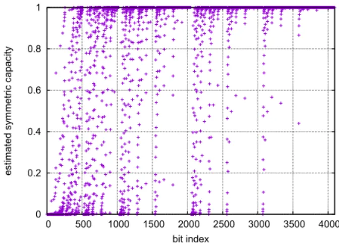
Figure 4 presents relation between the bit indexi of W2(in)
and symmetric capacityI(W2(i)n)estimated by the simulation
Fig. 4 Polarization of IDS channel (pi=pd=1.0×10⁻²,ps=1.0× 10⁻²,n=12).
Fig. 5 Relation between bit position and mutual information (pi=pd= 5.0×10⁻³,ps=0,SIR=9.31×10⁻¹).
Fig. 6 Relation between bit position and mutual information (pi=pd= 5.0×10⁻³,ps=1.0×10⁻²,SIR=8.53×10⁻¹).
described in Sect. 4.3, where pi = pd = 1.0×10⁻²,ps = 1.0×10⁻²,and n = 12. This simulation result suggests polarization ofW2(i)n similar to memoryless channels. For pi = pd =5.0×10⁻³ andps =0, Fig. 5 shows the relation
Fig. 7 Dependence of error rates on the code length N =2n(n ∈ {11,12,13,14},ps =0,R= 0.80,L=4).
Fig. 8 Dependence of error rates on the list sizeL∈ {1,4,8,16}(ps=0,n=12,R=0.80).
between bit position (sorted byI(W2(i)n)and normalized by code length N = 2n) and estimated symmetric capacity, wheren ∈ {10,11, . . . ,15}. The result suggests that longer codes have stronger polarization effect, and it is expected that the rate
(i ∈ZN
I(W2(i)n)>1−)
/Napproaches the channel SIR, 9.31×10⁻¹. Figure 6 presents the case of channel with substitution errors, whereps=1.0×10⁻². This channel also shows the polarization effect similar to Fig. 5.
5.2 Block and Bit Error Rates
The block error rate (BLER) and bit error rate (BER) of the presented coding are evaluated by simulations, where the positions of frozen bits are determined according to the procedure of Sect. 4.3 with 104 iterations. The value of frozen bit isui =0 for alli ∈ Ac, except in Paragraph (6) wherein the effect of frozen bit values on decoded error rate is examined. The CRC for SCL decoding is defined by generator polynomialg(x)=x8+x7+x6+x4+x2+1.
(1) Relation to the Code LengthN=2n
Figure 7 shows the BLER and BER for code lengths N = 2n, wheren ∈ {11,12,13,14}. Here, the horizontal axis is
the insertion/deletion probability pi = ps, the substitution probability isps=0, code rateR=0.80, and list sizeL=4.
It is observed that the error rate lowers with increasing code length, while at these code lengths, there exists considerable gap from the channel SIR.
(2) Relation to the List SizeL
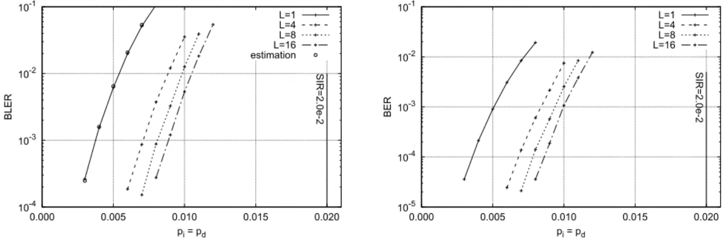
Figure 8 presents effect of the list sizeL∈ {1,4,8,16}on the decoded BLER and BER, where the code length is N=212 and code rate is R =0.80. The results show that the SCL decoding has much lower error rate compared to the SC decoding (L = 1), while the improvement diminishes for larger list sizes. This figure also shows the estimated BLER of SC decoding (L = 1) given by the right-hand side of Eq. (4). The estimation gives accurate values of BLER for the simulated parameters.
(3) Comparison to Marker-Based Codings
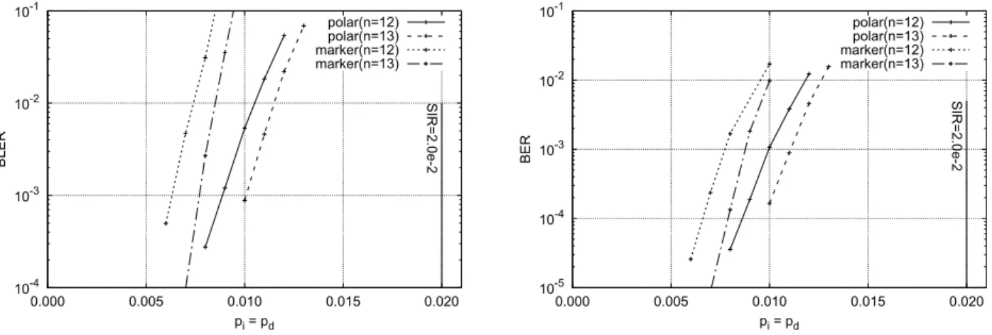
Figure 9 compares the error rates of the polar codes with those of marker-based coding [9], where ps = 0,n ∈ {12,13},R=0.80,andL=16. The outer code of the marker- based coding is binary (3,6)-regular LDPC code of rate 0.88, and the inner code is insertion of marker(0,1)with the reg- ular interval of 20 bits. The results show that the error rates
Fig. 9 Comparison to marker-based codings (ps=0,n∈ {12,13},R=0.80,L=16).
Fig. 10 Error rate when channel has substitution errors (ps=1.0×10⁻²,n=12,R=0.80,L∈ {8,16}).
Fig. 11 Error rates of low-rate codes (ps=0,n=17,R=0.44,L=8).
of polar code are lower than those of marker-based codings.
(4) Error Rates of Channels with Substitution Errors Figure 10 presents the error rates of polar code and marker- based coding when the substitution error probability isps= 1.0×10⁻², where the marker coding is with the interval of 96 bits. The polar codes have lower error rates compared to the marker-based coding, while discrepancy from the SIR
(=1.05×10⁻²) is large. For small insertion/deletion prob- abilities, e.g., pi=pd=1.0×10⁻³, substitution errors with probabilityps=2.0×10⁻² have a dominant contribution to the decoded error rates, and hence error rates do not fall sharply.
(5) Error Rates of Low-Rate Codes with Large Length Figure 11 shows the error rates of low-rate codes withR =
the marker-based coding is binary (3,6)-regular LDPC code of rate 0.58, and the inner code is insertion of marker(0,1) with the interval of 6 bits. The base matrix of SC-LDPC code isB(3,6,16)and the lifting number isM =4096. The results show that polar code has the lowest error rate among the evaluated codes.
(6) Effect of Frozen Bit Values
Table 1 lists the error rates for three cases of frozen bit values, where the values are determined as (a)ui =0, (b)ui =1, and (c)ui ∈Bwithp(ui=0)=p(ui=1)=1/2, fori∈ Ac. Here, the channel and code parameters are determined as ps = 0,n = 12,R = 0.80, and L = 16. The results do not show significant dependence of error rates on the frozen bit values, and thus it is expected that the IDS channel is symmetric with respect to input bit value.
6. Conclusion
This paper presented an SC decoding of polar codes modi- fied for IDS error channels, in which insertions and deletions are expressed by drift values. The recursive computations of original SC decoding is modified to include drift values in the calculation. The computational complexity of the SC decoding isO(D3)with respect to the maximum drift value D, andO(NlogN)with respect to the code lengthN. This also showed a simulation based estimation of symmetric ca- pacity of polar bit channels to determine the positions of frozen bits. Simulation results showed that the presented SC list decoding with CRC gives lower decoded error rates com- pared to the existing codes, such as spatially-coupled code, and concatenated coding with LDPC code and synchroniza- tion marker. Future works include reduction of decoding complexity by approximation, theoretical analysis and proof of polarization of polar bit IDS channel, theoretical analysis on the decoded error rate of the modified SC list decoding, and efficient determination method of frozen bits.
Acknowledgments
This work was supported by JSPS KAKENHI 18K04125.
References
[1] S. Zhang, K.S. Chai, K. Cai, B. Chen, Z. Qin, and S.M. Foo, “Write failure analysis for bit-patterned-media recording and its impact on
insertions, and reversals,” Soviet physics doklady, vol.10, no.8, pp.707–710, 1966.
[6] A.S.J. Helberg and H.C. Ferreira, “On multiple insertion/deletion correcting codes,” IEEE Trans. Inf Theory, vol.48, no.1, pp.305–
308, 2002.
[7] G. Tenengolts, “Nonbinary codes, correcting single deletion or in- sertion,” IEEE Trans. Inf. Theory, vol.30, no.5, pp.766–769, 1984.
[8] M.C. Davey and D.J. MacKay, “Reliable communication over chan- nels with insertions, deletions, and substitutions,” IEEE Trans. Inf.
Theory, vol.47, no.2, pp.687–698, 2001.
[9] F. Wang, D. Fertonani, and T.M. Duman, “Symbol-level synchroniza- tion and LDPC code design for insertion/deletion channels,” IEEE Trans. Commun., vol.59, no.5, pp.1287–1297, 2011.
[10] R. Goto, K. Kasai, and H. Kaneko, “Coding of insertion-deletion- substitution channels without markers,” Proc. 2016 IEEE Int. Symp.
Information Theory, pp.635–639, 2016.
[11] E. Arıkan, “Channel polarization: A method for constructing capacity-achieving codes for symmetric binary-input memoryless channels,” IEEE Trans. Inf. Theory, vol.55, no.7, pp.3051–3073, 2009.
[12] E. Şaşoğlu, E. Telatar, and E. Arıkan “Polarization for arbitrary dis- crete memoryless channels,” Proc. 2009 Information Theory Work- shop, pp.144–148, 2009.
[13] I. Tal and A. Vardy, “List decoding of polar codes,” IEEE Trans. Inf.
Theory, vol.61, no.5, pp.2213–2226, 2015.
[14] E.K. Thomas, V.Y.F. Tan, A. Vardy, and M. Motani, “Polar coding for the binary erasure channel with deletions,” IEEE Commun. Lett., vol.21, no.4, pp.710–713, 2017.
[15] K.D. Tian, A. Fazeli, and A. Vardy, “Polar coding for deletion chan- nels: Theory and implementation,” Proc. 2018 IEEE Int. Symp.
Information Theory, pp.1869–1873, 2018.
[16] S. Kudekar, T.J. Richardson, and R.L. Urbanke, “Threshold satu- ration via spatial coupling: Why convolutional LDPC ensembles perform so well over the BEC,” IEEE Trans. Inf. Theory, vol.57, no.2, pp.803–834, 2011.
Hikari Koremura received the B.E. and M.E. degrees in computer science both from To- kyo Institute of Technology, Japan, in 2017 and 2019, respectively. His research interests include polar coding for insertion, deletion, and substi- tution error correction.
Haruhiko Kaneko received the B.E., M.E., and Dr. Eng. degrees in computer science all from Tokyo Institute of Technology, Japan, in 1999, 2001, and 2004. He has been a post- doctoral research associate at Japan Aerospace Exploration Agency from 2004 to 2007. Since 2007, he has been an assistant professor at Tokyo Institute of Technology, and is now an associate professor. His research interests include error control coding and data compression for depend- able high-performance computer systems. He received the FIT young researcher award and the IBM faculty award in 2008 and 2010, respectively. He is a member of IEEE Computer Society, IEEE Information Theory Society, IEICE Japan, and IPSJ.