九州大学学術情報リポジトリ
Kyushu University Institutional Repository
STUDY ON ASSESSMENTS AND COUNTER MEASURES FOR THE STABILITY OF STOPE DUE TO THE PREVIOUS MINED-OUT ACTIVITIES IN CUT-AND-FILL
UNDERGROUND GOLD MINE IN MYANMAR
ナウン, ナウン
https://doi.org/10.15017/4060111
出版情報:九州大学, 2019, 博士(工学), 課程博士 バージョン:
権利関係:
i
STUDY ON ASSESSMENTS AND COUNTER MEASURES FOR THE STABILITY OF STOPE DUE TO THE PREVIOUS MINED-OUT ACTIVITIES IN CUT-AND-FILL UNDERGROUND
GOLD MINE IN MYANMAR
A DOCTORAL DISSERTATION
Submitted to the Department of Earth Resources Engineering Graduate School of Engineering
Kyushu University
As a partial fulfillment of the requirements for the degree of Doctor of Engineering
By
NAUNG NAUNG
Supervised by
Professor Dr. Hideki SHIMADA
Department of Earth Resources Engineering Graduate School of Engineering
Kyushu University Fukuoka, Japan
March, 2020
ii
ABSTRACT
In Myanmar, as the development of high-grade ore existing in the shallow area becomes to be important in recent years, the cut-and-fill method is suitable among the various underground mining methods for maintaining the stability of working stope and minimizing the impact of mining activities on the surface. Since the stope is filled with backfilling material such as waste rock, cut-and-fill method is a method that can control the stability of rock mass around the mined-out area and prevent surface subsidence.
Hence, the environmental impacts due to the mining activities becomes to be small.
Besides, the sill pillar is the ore that is left below the mined-out stope to prevent the collapse of working stope. The ore between surface and stope is also left as the crown pillar to maintain the stability of working stope and prevent the occurrence of subsidence.
Modi Taung gold mine which is targeted in this research is one of the largest underground gold mines in Myanmar and applies as an overhand cut-and-fill method. Since the rock mass condition in shallow area is poor and mechanical properties of rocks is weak, not only much supports have to be installed in the working stope but also a plenty of ore has to be left as sill pillar and/or crown pillar in order to maintain the stability of working stope and control surface subsidence. Moreover, the conditions of previous mined-out area also have an obvious impact on the stability of working stope and surrounding rock mass. From these backgrounds, the purpose of this research is to develop appropriate design guidelines and effective stabilization measures for sill pillar and crown pillar considering with the influence of previous mining activity. An attempt has been made to investigate the optimum design for sill and crown pillars and the effectiveness of stabilization measures by means of FLAC3D. This dissertation consists of six chapters and the main contents in each chapter are listed as follows:
Chapter 1: This chapter describes the mining industry in Myanmar, the background of this research, the overview of cut-and-fill mining method, the factors influenced on the stability of stope and subsidence and then the overview of problem statements in this research area. The objectives and the outline of the dissertation is also described in this chapter.
Chapter 2: This chapter describes the mining conditions of Modi Taung gold mine. The exploration works for this mine area have been conducted since 1996. The gold deposit is hosted in the sedimentary units of the Mergui Group, which is mainly composed of
iii
mudstone, sandstone, limestone and igneous intrusions. The cut-and-fill mining method is applied in this mine. Based on the results of laboratory experiments, the intact rocks in this underground mine are strong. However, according to the field observation and bore hole core logging, the rock mass in this mine has many discontinuities. From the results of laboratory tests and field investigations, it can be found that the rock mass condition in this mine site is very poor condition within 30 m depth from the surface, and poor to fair condition deeper than 80 m depth from the surface. Additionally, as heavy rain is a common in this mining region, the conditions in the underground openings at Modi Taung gold mine are very humid with meteoric water seeping through the geological structures.
As a result, weathering of the rock mass and backfilling material in the previous mined- out area was found and these conditions should be paid attention to the safety in order to prevent accidents due to the instability of rock mass around and inside of the stope.
Chapter 3: This chapter discusses the effect of previous mined-out area on working stope.
The mining operation in Modi Taung gold mine has been developed in shallow regions so far due to their easy access. Hence, the mining activities are going to extend the deeper levels below the previous mined-out area. Accordingly, a new stope developed below the previous mined-out area is influenced by not only its own induced stress but also the stress redistributions from the previous mined-out area. In order to evaluate the stability of working stope below the previous mined-out area, a series of numerical investigations are carried out in different geological and mining conditions in order to fully understand the stability of the stope and sill pillar due to the influence of previous mined-out activities.
From the simulation results, it can be found that the stability of rock mass around the stope obviously decreases with progression of the stope operation towards the upper slices, and then the failure zone propagates to the upper previous mined-out area. Therefore, the sill pillar should be left at least 3 m in thickness in order to stabilize the working stope for safe operation. The stability around the stope also decreases when the distance between the working stope and previous mined-out area is larger than 5 m, the monitoring of the rock mass around the stope should be conducted. As the feasible instability of rock mass is likely to occur more in lower vein dip, more severe geological conditions, wider stope width and higher horizontal-vertical stress ratio, the wider the sill pillars are required. Moreover, when the mining activities are carried out below the previous mined- out area, the effect of the conditions of backfilling material in previous mined-out area such as the deterioration of backfilling material and surrounding rock mass, filling rate
iv
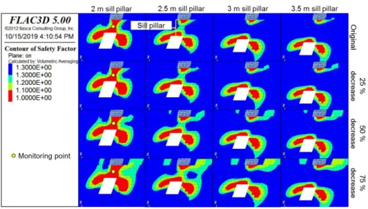
with backfilling material, have to be taken into account. For the considerations of the deterioration of backfilling material in the previous mined-out area, in the case that the mechanical properties of backfilling material decrease to 25 %, the thickness of sill pillar should be more than 3.5 m as the area of unstable rock mass around the stope and pillar increases. In addition, in the case of no backfill condition during mining activities in previous mined-out area, the sill pillar should be left more than 4 m in thickness in order to ensure the stability of the sill pillar and working stope under the previous mined-out area. From the above results, it can be concluded that not only geological and mining conditions but also the condition of mind-out area have an obvious impact on the stability of the working stope. Therefore, the condition of mined-out area adjacent of the working stope has to be investigated before designing the sill pillar and the support of the working stope.
Chapter 4: This chapter discusses the effect of the mining activity on the stability of the slope surface in different geological and mining conditions because most of the primary deposit of metal mines in Myanmar are located in mountainous regions and the stopes have been developed close to the slope surface. From the results of a series of numerical simulations, it can be found that rock mass under the slope surface is affected by unequal differential stress due to the weight of overlaying rocks, the instability of rock mass around stope arises and the failure zone can develop around the mining activities increase with decreasing the distance between stope and slope surface, especially in case that the distance is less than 25 m. Subsequently, mining activities under slope topography are affected more by the variation of stress and failure zones than other places of rock mass due to the influence of the slope condition. Moreover, as the failure zones around the stope are propagating to the slope surface when the distance between the stope and surface is less than 15 m. the subsidence of the slope surface may occur, and subsequently it may induce a slope slide. Therefore, the crown pillar should be left more than 20 m in thickness.
Additionally, the monitoring should be conducted when the distance between the stope and stope surface is less than 25 m in order to detect ground movement and prevent subsidence of slope and slope slide.
Chapter 5: This chapter discusses the countermeasures for maintaining the stability of the stope and surrounding rock mass affected by the previous mined-out activities and the slope surface. Two types of countermeasures, the installation of a cable bolt and shotcrete,
v
are selected and used to improve the stability of stope and pillars. From an economical point of view, the installation of a cable bolt is preferred to that of shotcrete due to its lower cost and faster installation, however the countermeasure with higher supporting capacity should be considered where the potential of rock failure is large. From the results of a series of numerical analyses, in the case where a new stope is developed below the previous mined-out area, it can be made clear that even though the stability of the rock mass around stope can be improved by the installation of cable bolts, the stability of sill pillar is not improved obviously and more than 3 m thickness of the sill pillar still needs to be left. On the other hand, the installation of shotcrete can improve the stability of the rock mass around the stope effectively and the thickness of sill pillar can be decreased from 3.0 m to 2.5 m. Moreover, it is also effective in wider stope and higher stress conditions. When the stope is developed near the slope surface, it can be said that the installation of cable bolts has no obvious impact on the stabilities of stope and slope surface. On the other hand, the installation of shotcrete can effectively improve the stability of the crown pillar, the thickness of crown pillar can be reduced from 20 m to 10 m. Therefore, it can be concluded that an optimum mining operation can be done according to the grade of ore by applying shotcrete.
Chapter 6: This chapter concludes the results of this research.
vi
ACKNOWLEDGEMENTS
First and foremost, I would like to express my special acknowledgement to my supervisor Professor Dr. Hideki SHIMADA, Laboratory of Rock Engineering and Mining Machinery of Kyushu University, for his valuable guidance and advice, kind understanding and encouragement, and support throughout my study in Japan.
I would like to extend my gratitude and appreciation to Associate Professor Dr. Takashi SASAOKA, my co-supervisor, Laboratory of Rock Engineering and Mining Machinery of Kyushu University, for his kindly assistance and precious suggestions during my research. My sincere thanks also go to the member of my examination committee, Professor Dr. Noriyuki YASUFUKU, Department of Civil Engineering of Kyushu University, for his valuable comments and constructive suggestions.
I would further like to send my sincere gratitude to Assistant Professors Dr. Akihiro HAMANAKA and Dr. Sugeng WAHYUDI, for their valuable suggestions, helpful assistances and supports for my research and smooth daily life during my study in Japan.
In addition, sincerely appreciation is also delivered to Japan International Cooperation Agency (JICA), for awarding the scholarship of KIZUNA program. I hope this program will be helpful to continue foster relationships between Myanmar and Japan mining industry.
I also would like to thankful to all members from our Laboratory, especially Dr. Pisith MAO and my senior, Dr. Phanthoudeth PONGPANYA, for their kindly supports, cooperative and friendship with happy and lasting memories.
Last but not least, I deeply express my special thanks from the innermost of my heart to my wife. I owe her a debt of gratitude for her endless love, support, patience and taking care of my kids over 5 years during I stayed in Japan. Thank you very much my dear! I also would not forget to thanks to my lovely kids, for being inspiration whenever I am down and missed you all. Without encouragements from them, it will be impossible to continue my study in here.
Naung Naung Fukuoka, Japan March 2020
vii
TABLE OF CONTENT
ABSTRACT…… ... ii
ACKNOWLEDGEMENTS ... vi
TABLE OF CONTENT ... vii
LIST OF FIGURES ... x
LIST OF TABLES ... xv
CHAPTER 1 Introduction ... 1
1.1. Mining industry of Myanmar ... 1
1.2. Literature review... 2
1.3. Mine instability in cut-and-fill underground mine operation ... 6
1.4. Objectives of this research ... 10
1.5. Outlines of dissertation ... 10
CHAPTER 2 Mine background, geology, and rock mass evaluations ... 12
2.1. Background ... 12
2.2. History of Modi Taung gold mine ... 12
2.3. Regional geology of Block 10 ... 15
2.4. Local geology and mineralization of Modi Taung gold mine (area A) ... 16
2.5. Rock mass evaluation from field observations and experiments ... 19
2.6. Conclusions ... 23
CHAPTER 3 Instability of stope mining under previous mined-out activities ... 24
3.1. Background ... 24
3.2. Current mine condition of Modi Taung gold mine ... 24
3.3. Description of numerical modelling and mining plan ... 25
viii
3.4. Failure criterion ... 27
3.5. Results for numerical analysis ... 28
3.5.1. Stability assessment for the influence of overlaying mined-out regions ... 29
3.5.2. Stability of sill pillars with its heights ... 32
3.5.3. Instability of sill pillar due to the effect of the deterioration of backfilling materials in previous mined-out regions ... 33
3.5.4. Stability assessment of stope under various geological conditions ... 35
3.5.5. Stability assessment of stope mining with different stope widths ... 38
3.5.6. Stability assessment of stope with various vein dips ... 40
3.5.7. Stability assessment of stope with different stress ratios ... 42
3.5.8. Stability assessment of stope with different backfilling materials ... 45
3.6. Discussions ... 48
3.7. Conclusions ... 49
CHAPTER 4 Risk assessments for the stability of slope surface due to stope mining ... 50
4.1. Background ... 50
4.2. Numerical modelling for simulations ... 51
4.3. Results ... 54
4.3.1. Slope stability and strength of rock mass under the slope surface ... 54
4.3.2. Assessment on the stability of stope mining near the slope surface ... 56
4.3.3. Parametric study on the stability of stope under slope surface in various mine conditions ... 59
4.4. Discussions ... 63
4.5. Conclusions ... 64
CHAPTER 5 Counter measures for the stability of stope openings ... 65
5.1. Background ... 65
ix
5.2. Countermeasure systems for stope instability ... 66
5.3. Optimization of stope stability under previous mined-out regions ... 68
5.3.1. Optimize the stope stability in different geological conditions ... 68
5.3.2. Optimize the stope stability in different stress ratios ... 71
5.3.3. Optimize the stope stability in different vein dips ... 74
5.3.4. Optimize the stope stability in different stope widths ... 76
5.4. Optimization of stope stability under mountain slope surface ... 78
5.4.1. Optimum crown pillar at the mountain slope surface ... 80
5.4.2. Optimum crown pillar with different geological condition under the mountain slope surface ... 83
5.4.3. Optimum crown pillar with different stress ratio under the mountain slope surface ... 84
5.5. Economic analysis for stope mining ... 85
5.6. Discussions ... 86
5.7. Conclusions ... 87
CHAPTER 6 Conclusions ... 89
REFERENCE….. ... 93
x
LIST OF FIGURES
Figure 1.1 Major ore deposits in Myanmar (modified from Khin Zaw, 2017). ... 1
Figure 1.2 Export incomes from mineral commodities of Myanmar (source: Ministry of Commerce, Myanmar). ... 2
Figure 1.3 Typical cave mining methods (1) longwall mining (2) sublevel caving (3) block caving, source: (Atlas Copco) (Dept: of Environment, Australia 2014). ... 3
Figure 1.4 Unsupported mining methods (1) room and pillar mining (2) stope and pillar mining (3) shrinkage stoping (4) sublevel stoping (source: Atlas Copco). ... 4
Figure 1.5 Supported mining method; (1) cut-and-fill mining (2) square-set stoping (3) stull stoping, source: (Karian.T, 2016) (Harraz 2016). ... 5
Figure 1.6 Simplified mine plan of Modi Taung underground gold mine (source: NPGPGL). ... 7
Figure 1.7 Rock mass condition showing discontinuities in Modi Taung gold mine. ... 8
Figure 1.8 Differential stresses by tension, compression and shear force. ... 9
Figure 2.1 Primary gold deposits in Myanmar (Ye Myint Swe et al, 2017). ... 13
Figure 2.2 Location of Modi Taung gold mine... 14
Figure 2.3 Geological map of Block 10 concession area (Mitchell et al. 2004). ... 14
Figure 2.4 Refined gold production of Modi Taung gold mine during NPGPGL period (source: No (2) Mining Enterprise, Myanmar). ... 15
Figure 2.5 Refined gold production of Myanmar (source: No (2) Mining Enterprise, Myanmar). ... 15
Figure 2.6 Myanmar regional tectonic map and location of Block 10 (IMHL 2003). ... 16
Figure 2.7 Detail geological map of Modi Taung gold mine (area A) (Erskine 2014). .. 17
Figure 2.8 Au vein systems mineralized in Modi Taung region (IMHL 2003). ... 18
Figure 2.9 Schematic diagram of Shwesin vein orientations (Erskine 2014). ... 19
Figure 2.10 Relation between RQD data and depth of Modi Taung gold mine (source: NPGPGL). ... 20
xi
Figure 2.11 Rock mass condition showing joints and cracks. ... 22
Figure 2.12 Underground adits condition seeping with meteoric water. ... 22
Figure 3.1 Mining plan at Shwesin vein system (source: NPGPGL). ... 25
Figure 3.2 Basic numerical model for research study. ... 26
Figure 3.3 Overhand cut-and-fill mine plan at Shwesin vein. ... 27
Figure 3.4 Mohr-Coulomb failure criterion. ... 28
Figure 3.5 Displacement of rock mass (A) condition without previous mined-out effects (B) condition with previous mined-out effects. ... 30
Figure 3.6 Failure zones occurring at the stope (A) condition without previous mined-out effects (B) condition with previous mined-out effects. ... 30
Figure 3.7 Unstable regions around the stope (A) condition without previous mined-out effects (B) condition with previous mined-out effects. ... 31
Figure 3.8 Safety factor indicators for various mining steps. ... 31
Figure 3.9 Failure zones of sill pillars with different pillar heights. ... 32
Figure 3.10 Contour of unstable regions of sill pillar with different pillar thickness. ... 33
Figure 3.11 Instability of sill pillar due to the effect of deterioration of backfilling materials in previous mined-out region. ... 34
Figure 3.12 Contour of safety factor with different deteriorations of backfilling materials in previous mined-out regions... 34
Figure 3.13 Instability of sill pillar with the influence of empty backfilling in previous mined-out region. ... 35
Figure 3.14 Failure zones around the stope with various geological conditions. ... 37
Figure 3.15 Contour of unstable regions around the stope with various geological conditions. ... 37
Figure 3.16 Safety factor indicators from stope advancing in various geological conditions. ... 38
Figure 3.17 Failure zones around the stope due to different stope widths. ... 39
xii
Figure 3.18 Contour of unstable regions due to different stope widths and pillars ... 39
Figure 3.19 Safety factor indicators from stope advancing in different stope widths. ... 39
Figure 3.20 Stress flow and displacement from the surrounding rock mass in different vein dip. ... 40
Figure 3.21 Failure zones around the stope due to various vein dips. ... 41
Figure 3.22 Contour of unstable regions around the stope and sill pillar due to various vein dips. ... 41
Figure 3.23 Safety factor indicators from stope advancing in various vein dips. ... 42
Figure 3.24 Failure zones around the stope due to different stress ratios. ... 43
Figure 3.25 Contour of unstable regions around the stope and sill pillar in different stress ratios. ... 43
Figure 3.26 Safety factor indicators from the bound of stoping sequence in different stress ratios. ... 44
Figure 3.27 Stress flow and displacement for high vertical stress and high horizontal stress. ... 44
Figure 3.28 Failure zones around the stope with various backfilling materials. ... 46
Figure 3.29 Contour of unstable regions around the stope and sill pillar with various backfilling materials. ... 46
Figure 3.30 Safety factor indicators with various backfilling materials. ... 47
Figure 4.1 Topography and mining plan at Shwesin vein system (source: NPGPGL). . 51
Figure 4.2 Basic model to analyze the effects of slope surface. ... 52
Figure 4.3 Monitoring points for differential stress under slope. ... 53
Figure 4.4 Stope mining and stoping sequence under slope surface. ... 53
Figure 4.5 Monitoring planes recorded for failure zone in this study. ... 53
Figure 4.6 Condition of slope stability with different slope angles. ... 54
Figure 4.7 Safety factor index with different slope angles. ... 55
Figure 4.8 Potential of rock mass instabilities at slope surface. ... 56
xiii
Figure 4.9 Differential stress measured under slope surface. ... 56
Figure 4.10 Differential stresses measured in the bound of stoping sequence under the slope surface. ... 57
Figure 4.11 Failure zones occurred in the bound of stoping sequence in different places from slope surface... 58
Figure 4.12 Rock instabilities occurred in the bound of stoping sequence in different places from slope surface... 59
Figure 4.13 Differential stresses measured in the bound of stoping sequence with various stress ratios... 60
Figure 4.14 Stress flow around the stope in different stress ratio under slope surface. . 61
Figure 4.15 Failure zones occurred in in the bound of stoping sequence with different stress condition. ... 61
Figure 4.16 Differential stresses measured in the bound of stoping sequence with different geological condition... 62
Figure 4.17 Occurrence of failure zones in the different geological condition under the slope surface. ... 62
Figure 5.1 Occurrence of failure zone after support system with different GSI under previous mined-out regions. ... 68
Figure 5.2 Contour of safety factor after support systems in different GSI under previous mined-out regions. ... 69
Figure 5.3 Safety factor index recorded from the bound of stoping in GSI 39. ... 70
Figure 5.4 Safety factor index recorded from the bound of stoping in GSI 42. ... 70
Figure 5.5 Safety factor index recorded from the bound of stoping in GSI 49. ... 70
Figure 5.6 Occurrence of failure zone after support system with different stress ratios. 72 Figure 5.7 Contour of safety factor after support systems in different K ratios. ... 72
Figure 5.8 Safety factor index recorded from lower stress ratio, K = 0.5. ... 73
Figure 5.9 Safety factor index recorded from higher stress ratio, K = 1.5. ... 73
xiv
Figure 5.10 Occurrence of failure zone after support system in different vein dips. ... 74
Figure 5.11 Contour of safety factor after support systems in different vein dips. ... 75
Figure 5.12 Safety factor index recorded from lower vein dip. ... 75
Figure 5.13 Safety factor index recorded from steeper vein dip. ... 76
Figure 5.14 Occurrence of failure zone after support system in different stope widths. 77 Figure 5.15 Contour of safety factor after supporting systems in different stope widths. ... 77
Figure 5.16 Safety factor index recorded from 3.5 m stope width. ... 77
Figure 5.17 Safety factor index recorded from 5 m stope width. ... 78
Figure 5.18 Failure zone in the stope mining under mountain slope surface with different support systems. ... 79
Figure 5.19 Rock mass instability of stope under slope surface with different support systems. ... 80
Figure 5.20 Rock mass instability propagated to the slope surface after installing different support systems. ... 82
Figure 5.21 Comparison of optimum crown pillar with different support systems. ... 82
Figure 5.22 Comparison of optimum crown pillar without support and shotcrete support with different geological conditions. ... 83
Figure 5.23 Comparison of optimum crown pillar without support and shotcrete support with different stress ratios. ... 84
xv
LIST OF TABLES
Table 2.1 RQD classification index (Deere et al. 1967). ... 20
Table 2.2 Intact rock parameters obtained from laboratory experiments. ... 20
Table 2.3 Rock mass properties evaluated with geological conditions. ... 23
Table 3.1 Rock mass parameters of basic model. ... 26
Table 3.2 Rock mass properties for simulations with various geological conditions. .... 36
Table 3.3 Properties of backfilling materials used in simulations. ... 45
Table 5.1 The properties of cable bolt used in analysis (Karian 2016). ... 67
Table 5.2 Properties of shotcrete (Karian 2016). ... 67
1
CHAPTER 1 INTRODUCTION
1.1. Mining industry of Myanmar
The mining industry is considered as one of the fastest growing economies all over the world but in particular, the countries who export mineral products can get more benefits for their economic development. Myanmar is a geologically-diverse country containing a wide array of mineral resources, such as gold, silver, copper, tin, tungsten, zinc, jade and gemstones as shown in Figure 1.1 (Zaw 2017) (Soe Win and Malar Myo Myint 1998) (Gardiner, Robb, and Searle 2014) (Connette et al. 2016). The country has one of the most diverse and richly endowed collections of natural resources in Southeast Asia and still remain unexplored of its various mineral commodities.
Figure 1.1 Major ore deposits in Myanmar (modified from Khin Zaw, 2017).
2
The extraction of mineral resources has been one of the major sources of income for national economy for many years, and mineral exports are likely to improve under the new Myanmar mines law and rules. So far, the contribution of export incomes from mineral products to the country’s economy is steadily increasing year by year as shown in Figure 1.2 (Ministry of Commerce 2019). After promulgating the amendments of Myanmar mines law in December 2015 and Myanmar mines rules in February 2018, Myanmar’s mining industry is expected to expand in the near future on higher foreign and domestic investments. Currently, the Myanmar government is encouraging proposals for new mining developments following a series of new reforms aimed at incentivizing investments. Because of the great potential of investments in various mineral commodities, mining sectors both surface and underground mining have to be developed in the near future of Myanmar.
Figure 1.2 Export incomes from mineral commodities of Myanmar (source: Ministry of Commerce, Myanmar).
1.2. Literature review
Mineral consumption is gradually increasing as the global standard of living increases and mineral demand will be largely concentrated in developing countries experiencing economic development progressively. This implies mineral extraction from greater depths both surface mining and underground mining. However, underground mining will become more important in the future as environmental and social concerns make surface mining less attractive (Karian 2016). Once the method is usually employed when the depth of the deposit and stripping ratio (waste to ore ratio) are too large to start a surface mining operation. It has been observed that there are many kinds of underground mining
3
methods, and ore extraction by an underground mining method involves many considerable range of functions. The design selection of a mining method requires a systematic approach, with the dip, size, and shape of an ore body, strength of the ore and host rock mass, as well as economics being some of the fundamental parameters influencing the planning and design process (Brady and Brown 2004) (Villaescusa 2014).
Reflecting the importance of ground support, underground mining methods are categorized in three classes on the basis of the extend of support required: supported method, unsupported method and caving method (Hartman 1987).
Caving method is typically applied to large, fairly flat-dipping ore bodies with rock mass characteristics that are amenable to sustainable massive caving. Three major caving methods are recognized i.e. longwall mining, sublevel caving, and block caving (Hartman 1987). Longwall mining is used in horizontal, tabular deposits and mainly employed to coal mining applications, while the other two methods have applied in inclined or vertical, and massive deposits. An understanding of cavability, fragmentation, and stress are primary elements in designing and operating a caving mine (Brannon, Carlson, and Casten 1992). Figure 1.3 shows the layouts of typical cave mining methods (Copco 2007) (Department of Environment Australia 2014).
Figure 1.3 Typical cave mining methods (1) longwall mining (2) sublevel caving (3) block caving, source: (Atlas Copco) (Dept: of Environment, Australia 2014).
4
Unsupported mining method, in which the host rock is essentially self-supporting and no artificial support is necessary to carry the load of overlaying rock. This method can be applied in room and pillar method, stope and pillar method, shrinkage stoping, and sublevel stoping (Okubo and Yamatomi 2009). The ore deposit type with flat-dipping and tabular shape can be employed with room and pillar whereas shrinkage and sublevel stoping are applied to steeply inclined ore bodies. However, the major concerns when applying these methods are the long term stability of the opening after mine closure.
Abandoned mine working possess subsidence threat in the future as reported by several researchers (Statham and Treharne 1991) (Longoni et al. 2016). Moreover, those methods offer 60 % to 80 % recovery due to the need to left pillar (Hartman 1987) (Brannon, Carlson, and Casten 1992). Therefore, some considerations upon ore recovery and safety issues are needed when unsupported mining method is employed to underground mining.
Figure 1.4 describes the layouts of unsupported mining methods (Copco 2007).
Figure 1.4 Unsupported mining methods (1) room and pillar mining (2) stope and pillar mining (3) shrinkage stoping (4) sublevel stoping (source: Atlas Copco).
Supported mining methods require some types of backfill to provide substantial amounts of artificial supports to maintain stability in the exploitation openings of mine, as well as systematic ground control throughout the mine (Hartman 1987). Supported methods are used when mine openings are not sufficient stable to remain excavations during mine
5
operation. In other words, the supported mining method is intended for application under the surrounding ground conditions ranging in competency from moderate to incompetent.
No field or laboratory tests have been devised to determine competency in large rock masses. In order to determine the rock mass is competence or not, the best empirical approaches is the rock quality designation (RQD) based on drill core evaluation. There are three specific methods in the supported mining method which are cut-and-fill stoping, stull stoping and square-set stoping (Hartman 1987). Cut-and-fill and stull stoping methods are intended for moderately competent rock, while square set stoping is suitable for the least competent rock. Cut-and-fill stoping is the only method of supported class in common use whereas stull stoping and square-set stoping are infrequently used and relatively unimportant today because of excessive labor intensity and very low productivity, in addition to a scarcity of skilled work forces and available timber resources (Okubo and Yamatomi 2009). Figure 1.5 describes a schematic diagram of supported mining method (Karian 2016) (Harraz 2016).
Figure 1.5 Supported mining method; (1) cut-and-fill mining (2) square-set stoping (3) stull stoping, source: (Karian.T, 2016) (Harraz 2016).
A description of cut and fill stoping is necessary to avoid confusion with similar practices that are part of other mining methods. The method is primarily utilized for steeply dipping vein deposits and large, irregularly-shaped deposits and ore value is relatively high
6
(Hamrin 2001). Ore deposit is mined in a horizontal slice while the mined out slice then backfilled by using backfill material to provide additional support for the country rock surrounding the stope. In fully-mechanized operation roadway is driven from the surface and connected to the stope by using cross cuts. High ore recovery rate (90% - 100%), adaptable to mechanization, possibility to use surface waste as filling material are among advantages of this method (Hartman 1987). Discontinuous operation due to filling operation is one of disadvantages of applying this method. Another major disadvantage is its cost which fairly expensive compared to the others due to labor extensive and, mainly, the application of backfilling. Backfilling application may take up to 20% of the total operating cost of the mine (Grice 1998). In addition, conventional ground support in the form of rock bolts, cable bolt, wire mesh, and shotcrete still will be required to temporarily support the stope openings during production mining.
There are numerous types of cut-and-fill mining methods, however the widely practiced method is overhand cut-and-fill mining method (Purwanto 2015). This type of mining typically done upwards from lower levels, so the backfill is used to provide a new working platform for further mining. Overhand cut-and-fill mining method can be applied in the good quality rock mass around the ore deposit. Application of overhand cut-and-fill method in weak rock mass is possible but may lead to excessive need of rock support (William A. and Richard L. 2001). In this method, Sill pillars and crown pillars are used to separate stope vertically to make a stable working environment. The dimensions of these pillars are determined by the geotechnical environment and the stresses induced by mining (Stephan 2011). As the stability of these pillars is one of the important issues in overhand cut-and-fill stoping, the optimum pillars should be determined to avoid the failure. Currently, most of the underground metal mines in Myanmar are applying the overhand cut-and-fill mining method in their operation.
1.3. Mine instability in cut-and-fill underground mine operation
Mine stability is the most important issues in underground mining. Mine development and/or production instability can cause production delay, loss of reserves, as well as injury to miners. As described above, most of the underground gold mines in Myanmar are operating with cut-and-fill mining method. However, the assessments on the stability of stope still remain quite limited. Currently, many underground gold mines are being mined-out or still mining at the easily accessible shallow places. After a period of mining,
7
easily accessible shallow mineral resources are being mined out and the deposits of rest mine are left in deeper regions. Therefore, underground mining activities are going to continue to progress into deeper levels to fulfill the demand of gold, for example, the mining plan of Modi Taung gold mine as shown in Figure 1.6. Accordingly, stress condition in deeper mine will be greatly changed and the mining process would be more complicated.
Figure 1.6 Simplified mine plan of Modi Taung underground gold mine (source:
NPGPGL).
The stability of deep underground excavations depends upon the strength of the rock mass surrounding the excavations and upon the stresses induced in this rock (Evert Hoek 2000).
Mining-induced stresses are the redistribution of field stresses as a result of the geometry and orientation of the excavations. Substantial stress redistribution directly influences the stability of the development openings. The effect of stress redistribution will vary depending on the geometry and orientation of the underground opening in relation to the in-situ stress field (Carlsson and Olsson 1993). Another factors affected the stability of underground excavation depend on the conditions of surrounding rock mass. The strength of rock mass will be reduced if there are many discontinuities and weathering of rock inside. At Modi Taung gold deposit, even though the host rock (intact condition) is strong, it can be found many discontinuities inside the rock mass especially in the oxidation zone
8
of host rock as shown in Figure 1.6. Additionally, heavy rainfall is one of the causes of weathering of rock mass. The rate of water charge increases after periods of heavy rain which is common in this area. This meteoric water interacts with the surrounding rocks which result in weathering of host rocks, leading to deterioration of host rocks. All these conditions will give effects to the instability of underground excavations and should be paid attention to prevent the opening collapse. Thus, it is important to understand the stability of stope under near the previous mined-out area due to the redistribution and accumulation of stress under previous mining activities.
Figure 1.7 Rock mass condition showing discontinuities in Modi Taung gold mine.
Another factors for instability of stope is the in-situ stress distribution characteristics of the rock mass near the slope surface and the redistribution of these effects to the stope.
Most of the primary gold deposits are generally hosted in mountainous regions in Myanmar. Considering the environmental and social impacts, therefore the underground mining method might be adopted in mountainous regions and the mining operations may be conducted under near the slope surface. Rock mass conditions under the slope surface may change under varying depths of overburden as well as the distribution characteristics of initial vertical and horizontal in-situ stresses (Li et al. 2017). If in-situ stresses are not equal from all directions, then the differential stress will appeared and affected to the surrounding rock mass. As well known, differential stress is the difference between the major and the minor principal stresses, and rock mass can deform (break/flow) due to differential stress. There are three kinds of differential stress: tensional stress which stretches rock, compressional stress which squeezes rock, and shear stress which result in slippage and translation (Nelson 2015) as shown in Figure 1.7.
9
Figure 1.8 Differential stresses by tension, compression and shear force.
In the mountain slope, the in-situ stress values are much greater than the predicted values according to the vertical overburden depth, especially within 100 m from the slope surface (Li et al. 2017). In these areas, the horizontal tectonic stresses are always larger than the vertical in-situ stress. Therefore, the in-situ differential stress of that areas to the slope surface exhibits a higher value owing to the mountain slope effect (Li et al. 2017).
Subsequently, the potential of rock instability become large at the mountain slope areas.
As described in above, the in-situ stress condition has an obvious influences on the stability of rock mass around the stope and slope surface. The rock medium is subjected to initial the stress prior to excavation. Finally, post-excavation state of stress in the structure is the resultant of the initial state of stress and stresses induced by excavation (Brady and Brown 2004). Therefore, the stability of stope under slope surface has to be paid attention not only by the stress induced by excavation but also the influence of topography.
In common practice, increasing crown pillar thickness under the slope surface could be a measure to prevent subsidence. The instability of stope will decrease with increasing the thickness of the pillars, however it will reduce mining recovery since higher volumes of ore body are left behind as a pillar (Stephan 2011). Therefore, determining the optimum thickness crown pillar and maintaining stope stability during ore extraction under the sloping area become the key to prevent surface subsidence and stope failure in cut-and- fill mining application.
10 1.4. Objectives of this research
As described above, most of the underground gold mines in Myanmar are being mined- out or still mining at the easily accessible shallow places. However, the assessments on the stability of stope still remain quite limited. Moreover, there are not so many recorded data regarding rock mass failures cases in underground mines of Myanmar. Hence, the study on the stability of stope under previous mined-out activities become one of the important issues to mitigate the unpredictable rock/slope failures. In addition, because the impact of in-situ stress conditiion at the mountain regions, the investigations on the potential instability of rock mass in slope surface and the stability of stope influenced by the topography/slope surface need to be discussed. Considering the importance of the stability of stope under different conditions mentioned above, the objectives of this research are listed below:
1. Understanding geological and geotechnical characteristics of rock mass in research mine site.
2. Investigating the stability of stope under previous mined-out activities in various mine conditions.
3. Evaluating the deformability of rock mass influenced by the mountain slope surface and the potential instability of underground mining affected by slope surface.
4. Introducing the effective rock supports as countermeasure method for stope stability by decreasing the risks of slope slide surface and the effect of previous mined-out activities.
1.5. Outlines of dissertation
The following chapters are included in this dissertation:
Chapter 1 introduces the background of this research, the overview of cut-and-fill mining method, factor affecting on the stability of underground mine opening, objectives of this research, and outlines of dissertation.
Chapter 2 describes the background of research mine site, Modi Taung gold mine, regional and detail geology, ore deposit and geotechnical informations of this mine site.
Chapter 3 discusses the potential instability of stope mining under previous mined-out
11
activities. The instability of new stope opening under overlaying mined-out regions are investigated in various mining conditions by means of numerical simulations.
Chapter 4 discussed the importance on the evaluation of rock mass condition before mining and the potential failure of surrounding rock during mining under sloping surface.
The occurrence of in-situ differential stress near the mountain slope and the influence of slope effects to the underground opening are investigated.
Chapter 5 introduces the application of countermeasures to maintain the stability of stope influenced by the effect of previous mined-out activities and the risk of slope failure. Two types of countermeasures, cable bolt and shotcrete support, are used to maintain the stability of stope and pillars.
Chapter 6 summarizes the conclusions of each chapter.
12
CHAPTER 2
MINE BACKGROUND, GEOLOGY, AND ROCK MASS EVALUATIONS
2.1. Background
Myanmar has more than 300 gold deposits across the country which are classified as either primary or alluvial types (Swe, Aye, and Zaw 2017). Most of the primary gold deposits are hosted at the mountainous regions as shown in Figure 2.1 and mostly are extracted by underground mining methods. Open stope mining is the most common mining method adopted in underground metal mines in Myanmar. However, the assessments on the stability of underground mining still remain quite limited in those mining industries. Moreover, there are not so many recorded data regarding rock mass failures cases in underground mining in cut-and-fill mining methods. Hence, the study on the stability of underground openings become one of the important issues to mitigate the unpredictable nature of rock failures. In order to understand the stability of underground excavation under previous mined-out activities and mountain regions, the purpose of this research, the investigations on deposit’s geology, host rock condition, and geotechnical characteristics are firstly carried out at the Modi Taung gold mine which is one of the largest underground gold mines in Myanmar.
2.2. History of Modi Taung gold mine
The Modi Taung gold mine is situated 1,200 m above sea level in approximately 150 km southeast of Mandalay and 385 km north of Yangon as shown in Figure 2.2. Alluvial gold was first discovered in local river of south of the Modi Taung lease area in 1996. In August 1996, an agreement was signed between the Ivanhoe Myanmar Holdings (Exploration) Ltd. (IMHL) and the government to explore in Block 10 area as shown in Figure 2.3, covering approximately 1,400 km2 in central Myanmar. Starting from that time, the company was carried out the exploration works in Block 10, and ceased operations in August, 2005. The IMHL has identified a 100 km2 gold district in their Block 10 area, the Modi Taung–Nankwe gold district, with features characteristic of slate-hosted mesothermal quartz–gold vein deposits (Mitchell et al. 2004). During IMHL period, the company had carried out 1,600 m of surface trenching, 7,000 m of underground drifting and raising, and more than 5,000 m of diamond drilling (IMHL 2003).
13
Figure 2.1 Primary gold deposits in Myanmar (Ye Myint Swe et al, 2017).
The mining lease was later taken over by the National Prosperity Group Production Group Limited (NPGPGL), a Myanmar based mining company, during October 2011 to February 2018. During their period, the company had explored for finding new gold discoveries, and many drilling projects are carried at Modi Taung gold mine. According to NPGPGL, the estimation of total gold reserve is 14,647 kg with the contribution of 2,193 kg from Htongyi vein, 167 kg from Seintaung (Htongyi vein), 2,421 kg from Sinthay (Htongyi vein), and 9,866 kg from Shwesin vein system. During NPGPGL mining periods, the refined gold production from Modi Taung gold mine had increased year by year as shown in Figure 2.4. Compared to the gold production of the whole Myanmar as shown in Figure 2.5, it can be seen that the contribution of the production of refined gold of Modi Taung gold mine is over half production of the whole Myanmar
14
yearly. Moreover, according to ore reserves, the potential of gold production in this mine in the future might be increased.
Figure 2.2 Location of Modi Taung gold mine.
Figure 2.3 Geological map of Block 10 concession area (Mitchell et al. 2004).
15
Figure 2.4 Refined gold production of Modi Taung gold mine during NPGPGL period (source: No (2) Mining Enterprise, Myanmar).
Figure 2.5 Refined gold production of Myanmar (source: No (2) Mining Enterprise, Myanmar).
2.3. Regional geology of Block 10
The Modi Taung – Nankwe gold district in Block 10 concession lies very largely within the slate belt of central Myanmar (Mitchell et al. 2004). This slate belt, consisting of a late Paleozoic slaty mudstone and sandstone succession, extends southwards through southern Myanmar, western Thailand and central Sumatra (see Figure 2.6). The Modi Taung – Nankwe mineralization is the first reported deposit of slate-hosted mesothermal quartz – gold veins in Southeast Asia, and it is interested due to the economic potential of gold district and potential for similar deposits elsewhere in the Slate belt (Mitchell et al. 2004). The deposit is hosted in the sedimentary units of the Mergui Group, which is composed of two dominant sedimentary formations. The lower part consists of massive
16
to laminated mudstone, sandstone, rare limestones and channel-fill pebbly wackes while the upper part includes several polymict conglomerates.
Figure 2.6 Myanmar regional tectonic map and location of Block 10 (IMHL 2003).
2.4. Local geology and mineralization of Modi Taung gold mine (area A)
The Modi Taung gold mine (area A) is situated in the southern part of Block 10 concession.
Block 10 concession is divided into five areas, A, B, C, D and E by Myanmar government.
The main areas of production are concentrated in area A, B and D with area A being the richest of ore deposit, most mined and the largest one.
There are three main veins in Modi Taung gold mine (area A) namely: Shwesin, Sakangyi, and Htonegyi (Mitchell et al. 2004). These veins are hosted by four main lithologies:
mudstone, sandstone-siltstone, limey sandstone or limestone, and igneous intrusions.
Mudstone is the predominant rock types in all vein systems but sandstone occupies short segments, and veins tend to occur along the inclined interface between sandstone and mudstone. Their competence and hardness increase with depth from soft clay immediately beneath soil cover to a hard rock that is tough and competent with the
17
exception of moderate hardness near and below the base of the oxide zone. Sandstone and siltstone are mostly silicified and cut by quartz stockworks, forming quartzite. Ground conditions are poor in Shwesin vein system and within 60 m from surface where partial oxidation has occurred (IMHL 2003). The detail geological structure of Modi Taung gold mine (area A) is shown in Figure 2.7 (Erskine 2014) (Traynor 2015).
Figure 2.7 Detail geological map of Modi Taung gold mine (area A) (Erskine 2014).
Almost all of the auriferous veins in Block 10 lie within the 25 km x 5 km Modi Taung – Nankwe gold district. Even though there are three main vein system in Modi Taung region, other vein systems are also mineralized in the surroundings as shown in Figure 2.8 (IMHL 2003). Veins in east of least area are dipping steeply to the west, while veins in the west are dipping steeply to the east (Mitchell et al. 2004). Each vein system consists of either a single vein, or multiple parallel vein separated by host rock. Vein width varies with elevation and ranges between centimeter and meter scale (Mitchell et al. 2004) (Erskine 2014). At Shwesin vein system, the vein consists of two main veins: eastern vein and western vein, both are striking NNW (Figure 2.9). Eastern vein maintains a constant
18
thickness of 40 cm and dips up to 80° to the west, and western vein dips 75° to the east and ranges in thickness from 60 cm to 140 cm (Erskine 2014). All veins are massive quartz and the oxidation is likely due to groundwater interacting with the ore through a leached zone. The Modi Taung gold deposit (area A) is economically viable due to three main reasons; it has concentrated high gold grades of 10-300 g/t Au and up to 3,000 g/t Au, large lateral extent and if further investigated may be proved to be even larger than expected, and steeply dipping veins that continue to depth which makes stoping and extraction of ore easier (Traynor 2015).
Figure 2.8 Au vein systems mineralized in Modi Taung region (IMHL 2003).
19
Figure 2.9 Schematic diagram of Shwesin vein orientations (Erskine 2014).
2.5. Rock mass evaluation from field observations and experiments
The instability of underground excavation depends on the behaviors of surrounding rock mass. Different rock types have different characteristics that can influence their mechanical behaviors. Therefore, knowledge and understanding of rock mass condition are essential for stability of underground excavations. The first step for describing rock mass is to examine rock mass properties determined by lithology, laboratory tests and field observation data. The second step is to determine the geotechnical information of rock mass for the purpose of rock engineering design such as numerical modelling, analytical calculation, etc. Considering the importance of rock stability in stope opening, field observation for lithology, geology and mining system was conducted, and laboratory experiments was carried out to get the physical properties of rock mass.
At Modi Taung gold mine gold mine, Htongyi Taung and Sakangyi vein systems are hosted by mudstone, while the host rocks in the Shwesin, Sakangyi and Momi Taung systems are predominantly mudstone or siltstone and the rest sandstone. As described in Section 2.4, host rocks from Modi Taung gold deposit are sedimentary units and rock mass conditions from shallow part are poor. From the borehole data, the RQD and depth from Modi Taung gold mine are shown in Figure 2.10 and the correlation between RQD value and rock mass quality is shown in Table 2.1 (Lucian.C. and E.M. 2013). According to this RQD data, the rock mass of Modi Taung gold mine can be classified as very poor
20
condition within 30 m from the surface, and poor to fair condition more than 80 m depth from the surface. Furthermore, rock mass parameters that obtained from laboratory experiments are shown in Table 2.2 and the uniaxial compressive strength of intact host rock and vein from Modi Taung gold mine are 148 MPa and 140 MPa, respectively.
However, some activities such as discontinuities, persistence, aperture, rock roughness, and weathering of rock are conducted to complete full estimation of rock mass condition.
Figure 2.10 Relation between RQD data and depth of Modi Taung gold mine (source:
NPGPGL).
Table 2.1 RQD classification index (Deere et al. 1967).
RQD Rock mass quality
0 – 25 % Very poor
25 – 50 % Poor
50 – 75 % Fair
75 – 90 % Good
90 – 100 % Excellent
Table 2.2 Intact rock parameters obtained from laboratory experiments.
ρ [kg/㎥] E [GPa] v [-] σt [MPa] φ [deg] C [MPa]
Host rock 2,717 19 0.25 10.4 58 18.5
Vein 2,667 12 0.22 3.8 71 11.1
21
According to these intact rock parameters, it can be seen that the rock mass strength of Modi Taung gold mine is strong. However, rock mass properties which do not consider geological structure are not proper if used into any form of analysis for the design of underground excavations. On the other hand, wrong engineering geological estimations will effect to all numerical analysis and calculations. For this situation, the Geological Strength Index (GSI) introduced by Hoek, E., Kaiser, P.K. and Bawden, 1995 is very essential to estimate the rock mass strength for different geological conditions (E. Hoek, Kaiser, and Bawden 1995). The Geological Strength Index (GSI) provides a number which, when combined with the intact rock properties, can be used for estimating the reduction in rock mass strength for different geological conditions (E. Hoek and Brown 1997). From the field observation at Modi Taung gold mine, many cracks and joints within rock mass are found in underground tunnels and stopes as shown in Figure 2.11.
These rock mass conditions will be effected to the instability of underground excavations and should be paid attention to prevent the collapse of stope.
Additionally, heavy rainfall is one of the causes of weathering the rock mass. From the annual rainfall data of Modi Taung area recorded by IMHL, the data shows an average annual precipitation of 2,228 mm with a maximum annual precipitation of 2,900 mm recorded in 2002 (unpublished exploration report of IMHL, 2004). Conditions in adits at Modi Taung gold mine are very humid with meteoric water seeping through geological structures in the hanging wall as well as foot wall. The rate of water charge increases after periods of heavy rain which is common for this area. The seeping pathways for meteoric water flow appear to be through a complex system of fracture in the weathered host rock (see Figure 2.12). These meteoric water are interacting with surrounding rocks and can be affected to the weathering of host rocks, and then reduced the strength of host rocks.
Consideration of rock mass condition including several factors such as RQD, joint spacing, the condition of joints, and weathering, the rock mass properties can be estimated as shown in Table 2.3.
22
Figure 2.11 Rock mass condition showing joints and cracks.
Figure 2.12 Underground adits condition seeping with meteoric water.
23
Table 2.3 Rock mass properties evaluated with geological conditions.
ρ [kg/㎥] E [MPa] v [-] σt [MPa] φ [deg] C[MPa]
Hanging wall 2,670 3,786 0.23 0.035 44 0.76
Foot wall 2,717 3,786 0.25 0.065 40 0.69
Vein 2,667 3,786 0.22 0.034 45 0.77
2.6. Conclusions
In this chapter, the preliminary studies about mine background, geological conditions, rock mass properties, and mineralization of Modi Taung gold mine are conducted to evaluate the stability of underground mining for next research. From the previous researches of IMHL, the Modi Taung gold mine is interested due to the economic potential of gold reserve and potential for similar deposits elsewhere in this area.
According to Traynor 2015, the Modi Taung gold deposit (area A) is economically viable for its high grade ore (10-300 g/t Au and up to 3,000 g/t Au), the deposit amount may be larger than expected, and veins are steeply dipping and can continue to depth which makes stoping and extraction of ore easier. All of these data can bring the interest for many investors in this gold mine.
Regarding the rock mass condition, the rock strength from Modi Taung gold mine is strong by seeing the intact rock parameters. However, according to the RQD data and field observations, the rock mass of Modi Taung gold mine is very weak in shallow regions and poor to fair rock mass condition in deeper regions. Therefore, these rock mass conditions have obvious impacts on the stability of slope/surface, accordingly it will affected to the slope slides and the instability of stope mining in shallow regions.
So far, the mine projects in Modi Taung gold mine are already developed in most of shallow ground parts, therefore the mine will be continued to the deeper levels under the previous mined-out regions. Accordingly, the influence of stress redistributions and potential of failure accumulation will be affected to the mine opening under the previous mined-out regions. Therefore, the investigations for the stability of underground mining should be conducted before the development of mining projects in Modi Taung area in the near future.
24
CHAPTER 3
INSTABILITY OF STOPE MINING UNDER PREVIOUS MINED- OUT ACTIVITIES
3.1. Background
Stability of underground openings is a major concern for the safety and productivity of mining operations. Mine development and/or production instability can cause production delay, loss of reserves, as well as injury to miners. Within the scope of this study, a series of open stope’s instability under the influence of overlaying mined-out regions were carried out with different mining scenarios at Modi Taung gold mine. So far, most of the shallow parts of Modi Taung gold mine are already mined-out and mining activities are going to continue to progress to deeper levels in order to fulfill the demand of gold. It has been well known that stress condition in deeper mine will be greatly changed and the mining process would be more complicated accordingly, particularly when it is operated under overlaying mined-out regions. Creating a new stope under overlaying mined-out regions is not easy considering the instability of mined-out regions can affect the stope.
The instability of new stope is not only due to its own induced stress but also the effect of the mined-out regions situated on upper part of the stope. Therefore, the understandings of ground behaviors and failure mechanisms of new stope due to the influence of overlaying mined-out regions are paramount to be studied.
3.2. Current mine condition of Modi Taung gold mine
As described in Chapter 2, there are three main vein systems in Modi Taung gold mine, and this study is focused in Shwesin vein system among these three main veins. At Shwesin vein system, the accessible shallow area has been already mined, hence, the deposits are left in deeper regions. Therefore, the mining plans to continue to deeper levels, in which separated into 6 blocks, namely from Block 1 to Block 6. The overall mine plan is illustrated in Figure 3.1. According to this mine plan, most of the blocks are located under previous mined-out regions, hence the new mine developments might be affected not only by its induced stress but also by the effects of induced stress from previous mined-out activities. Overhand cut-and-fill mining method is adopted to extract the minerals at Shwesin vein and the dimension of stope is 2.5 m in height and 2 m in width. The waste rocks from excavation are only used to both fill the stope and provide
25
permanent wall support for the lower mine-out cavity.
Figure 3.1 Mining plan at Shwesin vein system (source: NPGPGL).
3.3. Description of numerical modelling and mining plan
Numerical simulation is an effective way to examine the stability of a stope. In this study, the failure conditions of new stope because of overlaying mined-out regions were investigated by means of the 3D finite difference code (FLAC 3D) for preliminary study.
FLAC 3D is a numerical software which is widely used for analyzing stress and deformation around the surface and underground openings conducted in both soil and rock (Itasca Consulting Group Inc. 2012). The size of the basic numerical model is 250 m × 250 m × 250 m with 70 degrees in vein dip as shown in Figure 3.2. The bottom of the model was fixed in the vertical direction, the sides were fixed in the horizontal direction, and the surface was free in all directions. The slaty mudstone is a predominant rock type in Modi Taung gold mine, and therefore the hanging wall and footwall are assigned as homogenous model for simplification. The mechanical properties of host rock and vein for basic model are given in Table 3.1. Moreover, to obtain more precise result of the rock failure distribution, the smaller mesh size was created around the excavation area. Overhand cut-and-fill stope mining in Block 2 was conducted with the stope dimension of 2.5 m in height and 2 m in width as shown in Figure 3.3. During stoping
26
procedure, the stope 1 is firstly mined for overhand cut-and-fill method, and the model is computed for the stability of stope before backfilling. After that backfilling material is filled and analyzed for the stope 1, then the excavation is continued for stope 2. This sequence is advanced in the planned mining zone until the final stope 8. Block 2 is the planned mine zone with 24 m in height under overlaying mined-out regions with 100 m in height, and the total overburden above Block 2 is 150 m. This study is carried out for the stability of current stope in Block 2 in various mining conditions which is not only influenced by its own induced stress but also affected by overlaying mined-out regions.
Figure 3.2 Basic numerical model for research study.
Table 3.1 Rock mass parameters of basic model.
ρ [kg/㎥] E [MPa] v [-] σt [MPa] φ [deg] C[MPa]
Hanging wall 2,670 3,786 0.23 0.035 44 0.76
Foot wall 2,717 3,786 0.25 0.065 40 0.69
Vein 2,667 3,786 0.22 0.034 45 0.77
Filling rock 1,400 153 0.321 - 20.5 0.20
27
Figure 3.3 Overhand cut-and-fill mine plan at Shwesin vein.
3.4. Failure criterion
Mining objective is to recover ore as much as possible from the vein. However, safety of workers in the advancing stopes must be ensured. Potential hazards in the stopes are rock falls from the stope’s roof and buckling failures in the hanging wall and footwall. In order to stabilize the stope, a failure criterion must be selected. A factor of safety of 1.3 would generally be considered as a stability standard for a temporary mine opening while a value of 1.5 to 2.0 may be required for a permanent one (E. Hoek, Kaiser, and Bawden 1995).
However, the selection of an appropriate factor of safety is based upon engineering experience and field observation. In this research, the Mohr-Coulomb failure criterion is adopted as shown in Figure 3.4 and elasto-plastic behavior of the rock mass is used. The factor of safety (strength factor) is calculated by dividing the strength of rock mass by the induced stress of stoping activities to provide a basis of stability assessment as follows (W. Abdellah et al. 2014):
Factor of Safety = {c cosφ+ [(σ1+σ3)/2 x sinφ]} / [(σ1-σ3)/2]
where c is cohesion, is friction angle, σ1 is major principal stress, and σ3 is minor principal stress. In this research, a factor of safety (strength factor) of 1.3 is adopted for the stability of temporary stope mining. The stope was considered in a stable condition when Mohr-Coulomb strength factor is greater than 1.3 and unsatisfactory condition will meet when the safety factor is less than 1.3.
28
Figure 3.4 Mohr-Coulomb failure criterion.
3.5. Results for numerical analysis
In general, no one can estimate the rock mass is stable or not without numerical simulations. Determining the tunnels and stopes are stable or unstable should be based on yield zones from numerical simulations. Therefore, to understand the instability of stope opening under overlaying mined-out regions, numerical simulations were firstly conducted for the stope without overlaying mined-out effects compared with simulations for the stope with overlaying mined-out effects. Additionally, for more understanding of stope’s instability under overlaying mined-out regions, numerical simulations have been observed with various mine conditions such as different vein dips, different vein widths, different stress ratios for vertical/horizontal, different geological conditions and different backfilling materials. The explanations of failure terms given in the legend in Flac 3D software are as follows (Yasitli and Unver 2005):
1) “none” indicates no-failure zone,
2) “shear-n” indicates the region failed under shear loading and failure process is still in progress,
3) “shear-p” indicates the region failed under shear loading and failure process is stopped due to lowered amount of shear forces.
4) “tension-n” indicates the region failed under tensile loading, and failure process is still in progress,