Feasibility study of impact damage detection for CFRP structure by Lamb wave sensing using FBG/PZT hybrid system
__________________________________________________________________________________________________________
TOSHIMICHI OGISU, NORITSUGU NAKAMURA, YOJI OKABE, NOBUO TAKEDA AND TATEO SAKURAI
ABSTRACT:
This paper presents the results of a feasibility study for the development of an impact detection system. The system can detect an impact and impact damage during flight when a CFRP is used in the aircraft structure. We propose a damage monitoring system that can detect the damage occurring/growing in a composite material by detecting an elastic wave launched from a PZT element using an FBG optical fiber sensor. Furthermore, we verify that the change of waveform depended on the damage growth by using a coupon specimen and structural element specimen. This shows the possibility of hot-spot monitoring in a skin/stringer bonding region at a practical level.
On the other hand, the fracture behavior of composite materials is considerably complicated. Therefore, it is important to detect damages with several inspection methods. In particular, impact damage as one of the most important fracture modes can lead to a catastrophic fracture in the absence of a proper countermeasure. Therefore, it is important to develop a structural health monitoring system that can detect impacts and impact damages such as BVID, which are difficult to detect externally by visible inspection. Therefore, we carry out an investigation into impact detection using a damage detection system that is developed for composite materials using AWG-type filter. Using the developed system, we showed the possibility of detecting impacts and impact damages.
INTRODUCTION
It is now over 40 years since composite materials began to be employed for the weight reduction of aircraft structures. Nevertheless, the application of composite materials for the primary structure of aircrafts is currently not being promoted [1].
_____________
Toshimichi Ogisu, Fuji Heavy Industries Ltd., Aerospace Company, Advanced Technology Engineering/International Commercial Program Operation, Yonan 1-1-11, Utsunomiya, Tochigi 320-8564, JAPAN.
TEL: +81-(0)28-684-7237, FAX: +81-(0)28-684-1033, E-Mail: [email protected]
The application of composite materials for the fuselage of a business jet has been confirmed as a success story. However, the structural weight ratio of composite materials has remained at around 35%, even for the latest strike fighter.
Generally, the fracture behavior of a composite material is very complicated; a drawback is that damage occurrence/growth is very difficult to detect from the exterior [2,3]. This disadvantage was one of the major issues that prevented the wide application of composite materials. However, the resistance to its use has been gradually decreasing over the past few years; this has been triggered by the increased application (approximately 50% structure weight ratios) in the manufacture of B787 aircrafts and a further demand for weight reduction and energy conservation due to the very high fuel costs [4]. However, the abovementioned drawbacks of composite materials have not been overcome technically. Therefore, it is very important for airlines to know whether the integrity of an aircraft structure is confirmed when they consider future maintenance operations (e.g., repair and fatigue maintenance).
Thus, it is expected that the SHM (structural health monitoring) system is a very promising technology that can secure the integrity of the composite material structure.
DAMAGE MONITORING SYSTEM
Figure 1 shows a schematic of the basic damage monitoring system [5–7]. In this newly developed system, a piezo element functions as the actuator for elastic wave excitation while an FBG optical fiber works as the sensor (receiver). The detection principle of this system is based on the energy change of the received waveform. If a damaged section exists in the path of the elastic wave, the energy of the elastic wave will change. By detecting this change, the system can detect the damage to a composite structure. Figure 2 shows the damage monitoring system for an inaccessible critical region (hot spot) in a wing box structure in which the sensor and actuator are positioned.
Commercial FBG sensor systems are capable of detecting elastic waves with a frequency of several dozen kHz. However, their capability for damage detection is not satisfactory.
Hence, we adopt an AWG-type filter; this is highly sensitive to the displacements in the FBG gratings with microvibrations from strains due to an elastic wave launched from the PZT elements. Figure 3 shows the configuration of the AWG-type filter.
Personal Computer
PZT element
Digital Oscilloscope High speed reflective light detection system
Amplifier Function Generator
FBG sensor Lamb wave
Figure 1. Schematic overview of basic damage monitoring system
Figure 2. Damage monitoring system for Figure 3. Configuration of an AWG-type the wing box structure filter
IMPACT AND IMPACT DAMAGE DETECTION SYSTEM
An application of the SHM system is indispensability to secure the structural integrity of an aircraft structure that an application is expected in a widly use of composite material.For ensuring the wide use of composite materials, the application of the SHM system is indispensable. In particular, it is expected that users will demand a reduction in the maintenance cost and improved facilities for the inspection process. In order to satisfy these demands, impact damage detection will be important in addition to damage detection of debonding and delamination. Therefore, we have investigated whether impact damage detection can be achieved with the same device construction as in the case of damage detection systems. Hence, we have carried out a feasibility study to demonstrate the effectiveness of using the same device construction.
TEST METHODOLOGY
We prepared a structural element test specimen that simulated the skin/stringer bonding parts of an aircraft structure, as shown in Figure 4. The specimen consisted of a CFRP skin/stringer structure with 16 ply [+45/0/-45/90]
2squasi-isotropic laminate.
Impact loading was carried out by hummer hitting on the static without any forced restriction. However, the impact load was not assigned a specific damage level. Further, the impact load was located on the opposite side of the bonded stringer surface. The actual impact locations were four, as shown in Figure 4.
Figure 4. Setup of the impact detection experiment
FBG Sensor
PZT Film Actuator
AWG-type Filter
Processor
High speed FBG demodulator
Light source
Generator
Trigger PZT
impact
Impact location PZT Location FBG Location Trigger
PZT
impact impact
Impact location PZT Location FBG Location Impact location PZT Location FBG Location Impact location PZT Location FBG Location Impact location PZT Location FBG Location
In addition, Table 1 shows the positions of FBGs, which we used as sensors for impact detection. The FBG optical fiber sensors that we used for impact detection were of normal (250 μm) and small (52 μm) diameters, and the gage length corresponded to 10 mm and 1 mm, respectively. The FBG sensor located to same position for the longitudinal direction (X-axis) of the specimen. The output port of the AWG filter was selected for the elastic wave acquisition due to detect an impact uisng most neighborring ports for the center wavelength of the FBG sensor.
Table 1. Sensor location for impact detection
No. Sensor Note Gage length Location
1 FBG Small/Embedded 1 I-3
2 FBG Small/Bonded 1 I-3
3 FBG Standard/Bonded 10 I-2
PRELIMINARY TEST RESULTS FOR IMPACT DETECTION Results of elastic wave detection
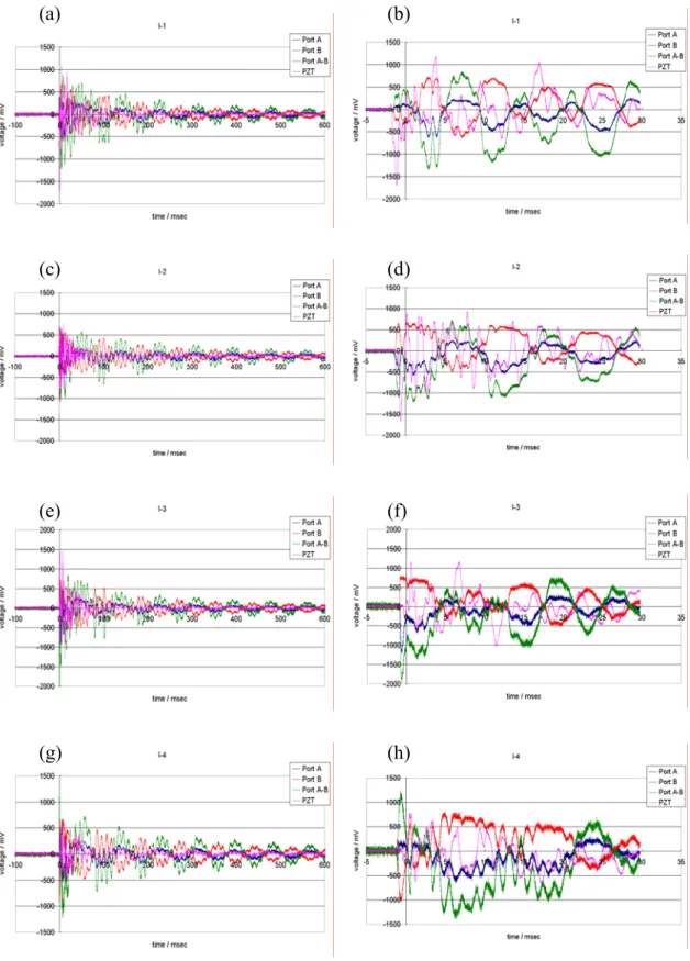
Figures 5 and 6 show the received waveform and the enlarged figure of the waveform of the elastic wave when we changed the impact position of FBG sensors No.
2 and No. 3. All the FBG sensors were available for elastic wave detection. In particular, FBG sensor No. 3 (normal diameter, gage length: 10 mm) showed the largest output among the three kinds of FBG sensors. On the other hand, we compared the performance of the FBG sensor with a small diameter for both the embedded and bonded cases. An embedded FBG sensor resulted in a large noise and small output signal when compared to a bonded FBG sensor. However, this depended on the intensity of the optical power and the embedded position. The waveforms generated by the impact showed a complexity in their initial part (0–50 ms). However, they showed a regular pattern after 50 ms. Further, it was not always same things that the received waveform by PZT which we used as a trigger of a measurement begining. In this feasibility study, we observed that signals from ports A and B were not symmetrical waveforms. It was assumed that this was because two reflection spectra chosen by an AWG filter were not displaced with regard to symmetry for the center wavelength of the FBG sensor.
Furthermore, when we change the travel distance of the elastic wave by changing
the impact location, the amplitude of the received waveform is not considerably
attenuated. From these test results, it is expected that a long gage and bonded FBG
sensor are suitable for impact detection by the abovementioned process.
Figure 5. Output waveform of FBG sensor No. 2 after impact loading (small/bonded)
(a) (b)
(c) (d)
(e) (f)
(g) (h)
Figure 6. Output waveform of FBG sensor No. 3 after impact loading (standard/bonded) (a) (b)
(c) (d)
(e) (f)
(g) (h)
Arrival time measurement for elastic wave
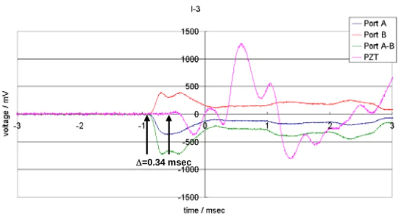
It is necessary to use the delay in the arrival time of the elastic wave received by more than three FBG sensors and the trigger from the PZT element for the identification of an impact location. In this study, when we assumed an impact location at I-3 in Figure 4, the received elastic wave at the bonded FBG sensor with a small diameter is shown in Figure 7. From the results, it was confirmed that the time difference of approximately 0.34 msec was caused by the delay in the arrival time of the elastic wave.
Therefore, the spread speed of the elastic wave was approximately 1.5 km/s because the spread distance during this period was 530 mm. However, this speed was somewhat low in comparison with that (A0 wave: 4 km/s, S0 wave: 8 km/s) calculated from the material stiffness of the specimen.
Thus, it was confirmed that impact detection was possible by observing the delay in the arrival time of the received elastic wave.
Δ=0.34 msec
Figure 7. Time delay measured by using the elastic wave received by FBG No. 3 (small/bonded)
CONCLUSIONS
In this study, it was verified that the acquisition of the waveform generated by a hammer strike by the FBG sensors of both the embedded and bonded types was possible.
Therefore, it was confirmed that the damage detection system had sufficient potential to function as an impact detection system without changing the device construction.
ACKNOWLEDGEMENTS
This study was conducted as a part of the “Civil Aviation Fundamental Technology Program—Advanced Materials & Process Development for Next-Generation Structures”
project under contract with RIMCOF (R&D Institute of Metals and Composites for
Future Industries), which was founded by the Ministry of Economy, Trade and Industry
(METI), Japan. We thank everyone associated with this project.
REFERENCES
1. M. V. Hyatt and S. E. Axter: Science and Engineering of Light Metal (RASELM ’91), Japan Inst. of Light Metals, pp. 273–280, (1991).
2. M. C. Niu, COMPOSITE AIRFRAME STRUCTURES, PRACTICAL DESIGN INFORMATION AND DATA, 1992, HONG KONG, CONMILIT PRESS LTD.
3. M. C. Niu, AIRFRAME, STRESS ANALYSIS AND SIZING, 1997, HONG KONG, CONMILIT PRESS LTD.
4. http://www.newairplane.com/ja-JP/Extras/TechnologySpotlight/composite.htm, accessed in Feb 2005.
5. T. Ogisu, M. Shimanuki, H. Yoneda, Y. Okabe, N. Takeda and T. Sakurai, “Evaluation of FBG/ PZT actuator hybrid damage monitoring system using structural element specimen”, Proc. 5th International Workshop on Structural Health Monitoring 2005, Stanford University, pp. 770–779, (2005).
6. T. Ogisu, M. Shimanuki, H. Yoneda, J. Kuwahara, Y. Okabe, N. Takeda and T. Sakurai,“Damage growth monitoring for bonding layer of the aircraft bonding structure using embedded FBG sensor/PZT actuator hybrid system”Proc. 13th SPIE Smart Structures and Materials 2006, 6171-12, (2006).
7. T. Ogisu, M. Shimanuki, H. Yoneda, Y. Okabe, N. Takeda and T. Sakurai, “Damage growth detection of aircraft bonding structure under cyclic loading using FBG/PZT hybrid sensor system”, Proc. 3rd European Workshop on Structural Health Monitoring 2006, University of Madrid, pp. 220-227, (2006).
![Figure 1 shows a schematic of the basic damage monitoring system [5–7]. In this newly developed system, a piezo element functions as the actuator for elastic wave excitation while an FBG optical fiber works as the sensor (receiver)](https://thumb-ap.123doks.com/thumbv2/123deta/6076007.2080310/2.892.259.648.871.1046/figure-schematic-monitoring-developed-functions-actuator-excitation-receiver.webp)