九州大学学術情報リポジトリ
Kyushu University Institutional Repository
金属ナノ粒子担持配位高分子における担体効果
吉丸, 翔太郎
https://doi.org/10.15017/4059997
出版情報:Kyushu University, 2019, 博士(理学), 課程博士 バージョン:
権利関係:
Support effects of MOFs in their composites with metal nanoparticles
金属ナノ粒子担持配位高分子における 担体効果
Shotaro Yoshimaru
March 2020
Department of Chemistry Graduate School of Science
Kyushu University
Contents
Chapter 1. General introduction ... 1
1-1. Support effect ... 1
1-2. Metal–organic frameworks ... 9
1-3. Purpose of this thesis ... 13
I. Electronic interaction between metal NPs and MOFs ... 14
II. Substrate adsorption by MOFs ... 15
1-4. References ... 16
Chapter 2. Preparation of Pt/MOFs ... 19
2-1. Introduction ... 19
2-2. Experimental ... 21
2-2-1. Preparation of MOF supports ... 21
2-2-2. Preparation and characterization of Pt/MOFs ... 25
2-3. Results and Discussion ... 26
2-4. Conclusions ... 39
2-5. References ... 40
Chapter 3. Charge transfer effect on Pt/MOFs ... 43
3-1. Introduction ... 43
3-2. Experimental ... 44
3-2-1. Evaluation of electronic properties of Pt/MOFs. ... 44
3-2-2. Characterization of the catalytic performance ... 49
3-3. Results and Discussion ... 50
3-4. Conclusion ... 61
3-5. References ... 61
Chapter 4. Substrate adsorption of Pt/MOFs ... 63
4-1. Introduction ... 63
4-2. Experimental ... 65
4-2-1. Acetic acid tolerance ... 65
4-2-2. Characterization of a behavior of acetic acid adsorption ... 66
4-3. Results and Discussion ... 69
4-4. Conclusions ... 95
4-5. References ... 96
Chapter 5. General Conclusion ... 97
1
Chapter 1. General introduction
1-1. Support effect
Present industries such as inorganic chemical, coal and petrochemical industries are deeply committed by heterogeneous catalysis represented by fixed-bed catalytic reaction, e.g. H2
production from methane and ammonia production by Harbor-Bosch process, exhaust emission and so on. The Harbor-Bosch process using Fe catalysts has been producing over 1 billion tons of ammonia all over the world.1 Vanadium oxide catalyst has been used for producing sulfuric acid by contact sulfuric acid method.2 So far, for purification of exhaust gas from automobile’s engine3 and a solid catalyst for fuel cell, application examples of precious metals including Pt has been increasing.4a According to a report,4b 90% of chemical processes all over the world are operated using a catalyst. This way, human beings strongly depend on catalysts. However, precious metals such as Pt are well-known as a highly active catalyst for many catalytic reactions were often used in various chemical process although such kinds of metals are very expensive and the reserves of them are limited. In other words, it is important to enhance catalyst’s performance to maintain and enrich our living.
For the last several decades, metal nanoparticles (NPs) have attracted much attention as a fascinating catalyst material. Many researchers have also invented and improved the metal NPs for various heterogeneous chemical reactions because the metal NPs have many advantages.
For example, the specific surface area of metal NPs is much larger than that of bulk one, which result in increasing its catalytic activity per weight and decreasing needed amount of the metal5. Besides, the size-related properties (e.g. electronic structures and optical properties) of metal NPs can enhance the catalytic activity.6 Therefore, many kinds of preparation and modifying method of metal NPs, i.e. a controlling size and morphology, 7 alloying8 and so on, have been reported for the heterogeneous catalyst.
2
Application of a support is another approach for improvement of catalytic activities. In general, metal NPs without any fixation easily aggregate and become too large to show its unique properties by mechanical and thermal treatments. Such an aggregation often diminishes its catalytic activity. Then, a catalytic support (e.g. metal oxides and carbon) is frequently used to fix the metal NPs on the surface when the metal NPs are applied for the heterogeneous catalysis.
In a study of the catalyst with metal NPs, the catalytic activity and the selectivity can be modified by a property of the catalytic support, which is called “support effect”. Several kinds of support effects have been eagerly researched in the heterogeneous catalysis, e.g., “an electronic interaction between metal NPs and a catalytic support”, “substrate adsorption by a support” and “molecular sieving effect” as shown in Figure 1-1. Support effects can be classified into three types as below.
Figure 1-1. Schematic images of the typical support effects
In the beginning, I introduce about a support effect of “an electronic interaction between metal NPs and a catalytic support” by showing an example about a water-gas shift reaction using a catalyst with Pt NPs9,10. The water-gas shift reaction is an exothermic reaction which produce H2 and CO2 from H2O and CO. This reaction proceeds as follows:
H2O (g) + CO (g) → H2 (g) + CO2 (g)
There are many reports which applied many types of catalysts for the water-gas shift reaction, e.g., composites of Pt NPs and Al2O3, CeO2, ZrO2, CeO2/ZrO2, TiO2 and so on.10 As a result of these reports, it was found that the catalytic activity of loaded Pt NPs depends on the type of
3
support because the interface between the Pt NPs and the support plays a key role on the reaction.
For example, Illas et al. reported how the support influence on the loaded Pt NPs using a composite catalyst of Pt/CeOx/TiO2 for the water-gas shift reaction.11 The Pt/CeOx/TiO2 (x = 0–2) was prepared by loading Pt NPs on a complex oxide of CeO2 and TiO2 by an electron beam deposition method. The loading amount of Pt NPs was controlled to be 0.1, 0.2, 0.3, or 0.5 monolayer (ML). XPS measurement of Pt4f and Ti3s of the catalyst revealed that the binding energy of Pt4f5/2 and Pt4f7/2 in Pt/CeOx/TiO2 with low amount of Pt (0.1–0.3 ML) is higher than that of bulk Pt as shown in Figure 1-2a. However, the binding energies of Pt4f5/2
and Pt4f7/2 in Pt/CeOx/TiO2 with high amount of Pt (0.5 ML) were almost the same as those of bulk Pt. These results indicate that there is an electron-drawing from Pt NPs by the CeOx/TiO2
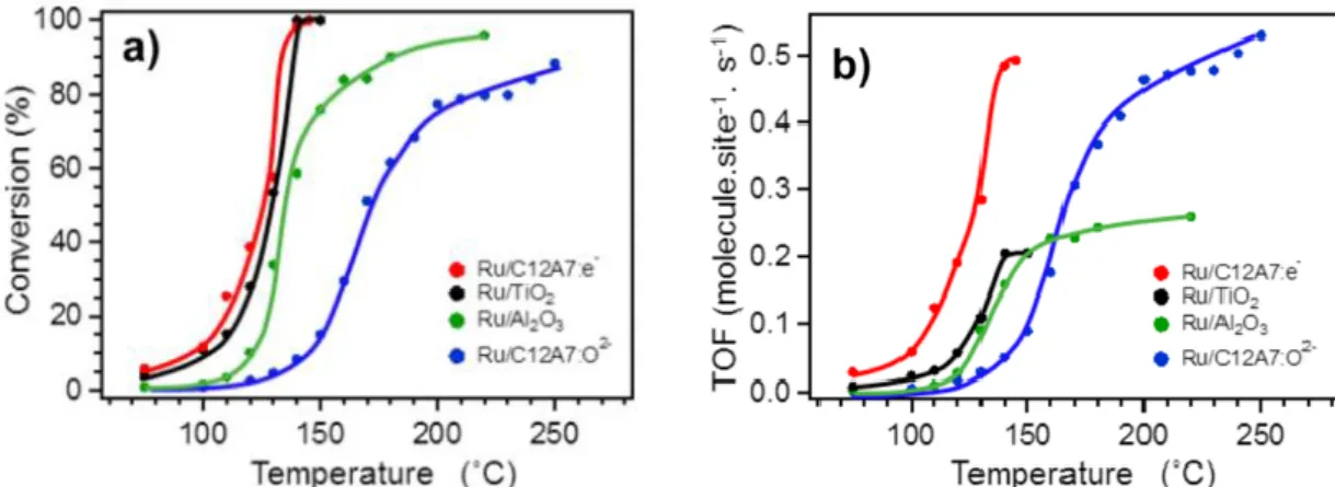
and reflects that the extractable amount of electron by the support is finite. Figure 1-2b shows the catalytic activities of the Pt/CeOx/TiO2 in the water-gas shift reaction, which is depicted as functions of the coverage ratio of TiO2 by CeOx. This result demonstrates that the electronic interaction depends on the coverage ratio of TiO2 by CeOx, which modifies the catalytic activity of the loaded Pt on the water-gas shift reaction. This clearly proves that favorable electronic- drawing ability of the support can enhance catalytic activities of the loaded metal NPs through a modification of their electronic states by a charge transfer interaction between a support and loaded metal NPs). Recently, an electron-donating to metal NPs from a support has also attracted much attention. For example, Hosono et al. reported that an electron-doped C12A7:e- electride: ([Ca24Al28O64]4+(e−)4) can play a role as an electron-donating support for CO oxidation reaction on Ru NPs12. The reaction formula of the CO oxidation reaction is as follows:
CO (g) + 1/2O2 (g) → CO2 (g)
4
Figure 1-2. (a) XPS spectra of Pt/CeOx/TiO2 with different coverages on Pt (0.1, 0.2, 0.3, or 0.5 ML, ML = monolayer), (b) the catalytic activities of Pt/CeOx/TiO2 and Pt/TiO2 (indicated as No CeOx) in the water-gas shit reaction. The percentage (11% and 23%) represent the coverages of TiO2 by CeOx. Cu/ZnO is indicated as a reference.
The C12A7:e- electride is one of the metallic conductors with high electron-donating ability originating from the electrons coordinated as anions and indicated as (e-) in the chemical formula of ([Ca24Al28O64]4+(e−)4). The same amounts of Ru NPs (2 wt%) were loaded on the C12A7:e-, ([Ca24Al28O64]4+(O2−)2) (C12A7:O2-), TiO2 and Al2O3. The composites are named as Ru/C12A7:e-, Ru/C12A7:O2-, Ru/TiO2 and Ru/Al2O3. Note that these sampleswere prepared in the same method using Ru3(CO)12 to make themselves comparable.
Figure 1-3a indicates the temperature dependences of CO conversion. Turn over frequencies (TOF) on the four catalysts is shown in figure 1-3b. The authors reported that there are a significant difference in the catalytic activities and TOF on the Ru/C12A7:e- is superior to that on Ru/C12A7:O2-, Ru/TiO2 and Ru/Al2O3 for the CO oxidation reaction.12 The significant difference was explained by the electron–donating power as below. Here, the catalytic supports can be categorized into reducible oxides (TiO2) and non-reducible oxide (C12A7:e4-, C12A7:O2- and Al2O3). In the reaction on Ru/TiO2 constituting of a reducible oxide, the CO
5
molecule adsorbs on the surface of Ru NPs. Then, the CO molecule is oxidized to CO2 by a lattice oxygen which is refilled by the reaction gas because the TiO2 is a reducible oxide which can release its lattice oxygen. Over Ru/C12A7:e-, Ru/C12A7:O2- and Ru/Al2O3 constituting of non-reducible oxides, not only the CO but also O2 in the reaction gas adsorb on the Ru NPs.
The anti-bonding orbital (2π*) of the adsorbed CO molecule receives an electron from a d orbital of the Ru NPs, which increases a polarization of a CO molecule. CO2 is produced from the polarized CO molecule and O2 which is activated on the Ru surface. This phenomenon results in an oxidation from not only an oxygen of the support material but the activated O2 (or O adatom) on the surface of Ru NPs (as shown in Figure 1-4). Both two factors: the polarization of CO and the activation of O2 can be enhanced by electron–donation from the catalytic support to the Ru NPs. Furthermore, the low catalytic activity of C12A7:O2- with a low electron- donativity as the support13 also suggests that the difference of reaction activity derives from the high electron-donation ability of the C12A7:e-. Note that the C12A7:O2- and C12A7:e- have almost the same structures. Incidentally, as a result of the difference in the reducibility of these supports, the low catalytic activity of Ru/Al2O3 is explained that the Al2O3 cannot play a role as oxygen source nonetheless all the other supports can give its surface oxygen for the oxidation of CO.14
As above, an electronic interaction between metal NPs and a support greatly affect the catalytic performance. This effect has recently been denoted as an electronic metal–support interaction (EMSI).
6
Next, I describe about a gas-phase acetic acid hydrogenation, i.e. ethanol production reaction from acetic acid, to introduce “substrate adsorption by a support”. In case that a composite of metal NPs is used as a catalyst for the acetic acid hydrogenation reaction, kinetic calculations15 suggest that the metal NPs unintentionally catalyze a thermal decomposition reaction of acetic acid, in other words, ethanol cannot be a main product in the acetic acid hydrogenation unless the thermal decomposition is suppressed by certain interaction such as a substrate adsorption on a catalytic support. Rachmady et al.15 reported about this effect. Composites of Pt NPs loaded on TiO2, Al2O3, SiO2 and Fe2O3 (0.69% Pt/TiO2 (HTR), 0.69% Pt/TiO2 (LTR), 2.01% Pt/TiO2
(LTR), 0.78% Pt/Al2O3, 0.49% Pt/SiO2 and 1.91% Pt/Fe2O3) were prepared in an incipient Figure 1-4. (a) Scheme of Ru/TiO2 and (b) Ru/ C12A7:e-. Orange arrows indicates
movements of charges.
(a) (b)
Figure 1-3. (a) Temperature dependence of CO conversion and (b) calculated TOF of Ru/C12A7:e-, Ru/TiO2, Ru/Al2O3 and Ru/C12A7:O2-
7
wetness method. The percentage indicates the amount of loaded Pt NPs. The Pt/TiO2 was treated by two different reduction temperatures either a low-temperature reduction at 473 K (LTR) or a high-temperature reduction at 773 K (HTR). The catalysis was conducted using a mixed gas of H2 and acetic acid vapor in a fixed bed reactor. Figure 1-5a present the rate of acetic acid consumption on the catalysts for the acetic acid hydrogenation reaction. The three Pt/TiO2
showed remarkably high activities. Focusing on the product selectivity as shown in Table 1-1, the selectivity of ethanol is different among the three types of Pt/TiO2. The 2.01% Pt/TiO2 (LTR) exhibited the highest ethanol selectivity of 70%. The result of the catalysis while changing partial H2 pressure and a kinetic analysis of it, revealed that the acetic acid–adsorption abilities of TiO2 (LTR) is stronger than that of TiO2 (HTR). Therefore, the authors concluded that the ethanol selectivity on acetic acid hydrogenation can be enhanced by acetic acid–adsorption ability of supports as shown in Figure 1-6.
Figure 1-5. Temperature dependences of (a) catalytic activities and (b) TOF on the acetic acid hydrogenation reaction using Pt NPs loading catalysts.
8
Table 1-1. Product selectivity on the acetic acid hydrogenation
Figure 1-6. Schematic images of gas-phase acetic acid hydrogenation reaction using Pt NPs loading (right) on Al2O3 and (left) on TiO2.
As these examples indicated, a catalytic support plays very important role which substantially influence on the catalytic activity of loaded metal NPs in heterogeneous catalysis. There are also some reports about the support effect of such as active carbon16, carbon nanotube17 and graphene18. However, a controllable range of physical properties of such materials are limited although various attempts have been performed. In addition, because the differences among these materials are too a lot (e.g. constituent elements, electronic structure, surface property and so on), it is very difficult to do systematically comparison of a property of the support and its effect on the catalytic activity of loaded metal NPs.
9
As I mentioned above, there is still a huge frontier in the support effect on the heterogeneous catalysis. An ideal systematic investigation of the support effect can be achieved with a novel material group which has much variation in its physical properties, such as including an electronic property and a substrate adsorption ability, with high diversity and designability.
Such a study helps us understand a control factor of the catalytic activity and an optimal property of a support.
1-2. Metal–organic frameworks
Metal–organic frameworks (MOFs) are receiving increased attention as a new class of highly ordered porous materials which are well-known for their tremendous variation and designability. MOF is a kind of an organometallic complex consisting of metal ions and organic ligands as shown in Figure 1-7. Basically, the wide range of options for the components and high diversity of structures of the complex are the origin of the tremendous variation of MOFs. Moreover, the porous structure can play roles in various situations. Therefore, the MOFs are establishing its position as hopeful materials which are potentially suitable for various applications such as gas storage,19 separation,20 controlled deliveries,21 and magnetic22 and conductive materials.23 Recently, MOFs have also been increasingly studied as a catalytic support because they possibly show specific support effects, such as molecular sieving, charge-transfer, and selective adsorption of substrate molecules in heterogeneous catalysis. Several researchers have reported on various catalytic reactions with the molecular sieving effect, using composites of metal NPs and MOFs as below.
10
Figure 1-7. Components of metal–organic frameworks
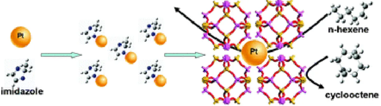
For example, Li et al. reported24 a molecular sieving effect on hydrogenation of n- hexene using Pt@ZIF-8 where PVP-coated Pt NPs are encapsulated by ZIF- 8:{Zn(MeIM)2} as shown in Figure 1-8. Note that “@” means encapsulation of metal NPs in MOF a crystal. Figure 1-9a shows temperature dependence of conversion of n- hexene to 1-hexene on Pt@ZIF-8 (Pt = 0.23, 0.57 and 0.74 wt%) and Pt NPs (1 wt%) loaded on carbon material. In all temperature range, Pt@ZIF-8s shows superior conversions compared to Pt/C. Meanwhile, when I focus on that the conversion of n- hexene to cyclooctene, Pt/C was superior to Pt/ZIF-8s as shown in Figure 1-9b. From comparison of molecular sizes of n-hexene (1.7 Å) / cycleoctene (5.5 Å) and pore size of ZIF-8 (3.4 Å), they concluded that the drastic difference in catalytic selectivity is resulting from a molecular sieving effect, i.e. n-hexene can contact with Pt through pore windows of ZIF-8, however, cyclooctene cannot contact with Pt because its size is too large to through the pore.
11
Figure 1-8. Molecular sieving effect of Pt@ZIF-8 on hydrogenation of n-hexene.24
Figure 1-9. (a) conversions for 1-hexene of each catalyst. (b) TOF of 1-hexene and cyclooctene, respectively.24
Duan et al. also reported25 a molecular sieving effect observed on single NPs@MOF core–
shell nanohybrid catalysts for the reduction of 4-nitrophenol and methylene blue. They prepared Au NPs loaded on Fe2O3 particles (MagNPs) coated with polydopamine (PDA) (MagNP@PDA@AuNPs), MagNP@PDA@AuNPs coated with ZIF-8 crystal (MagNP@PDA@AuNPs@ZIF-8) and MagNP@PDA@AuNPs coated with UiO-66 crystal (MagNP@PDA@AuNPs@UiO-66). TEM images of these catalysts are shown in Figure 1-10.
The composites were applied to 4-nitrophenol and methylene blue reduction reaction, respectively. In 4-nitrophenol reduction reaction, MagNP@PDA@AuNPs and MagNP@PDA@AuNPs@UiO-66 showed almost 100% conversion, whereas, MagNP@PDA@AuNPs@ZIF-8 did not promote the catalytic reaction. as shown in Figure 1-
12
11a. On the other hand, on methylene blue reduction reaction, only MagNP@PDA@AuNPs showed significant catalytic activity nevertheless all the other catalysts did not (Figure 1-11b).
In brief, the catalyst with bare AuNPs has a significant activity however the catalyst with AuNPs coated by ZIF-8 have no activity. On the reaction with 4-nitrophenol, the catalyst with AuNPs coated by UiO-66 only has an activity. These difference of reaction selectivity is attribute to a kind of molecular sieving effect originating from the sizes of pore windows. On 4-nitrophenol reduction, the reactant with molecular length of 4.8 Å can pass through the pore of UiO-66 shell with pore diameter of 6.0 Å and contact with Au NPs although cannot do through the one of ZIF-8 shell with pore diameter of 3.4 Å. This difference in the pore size of MOFs creates a situation that MagNp@PDA@AuNPs@UiO-66 shows a significant catalytic activity nevertheless MagNp@PDA@AuNPs@ZIF-8 does no activity. On the reaction of methylene blue with molecular length of 7.8 Å, the reactant is larger than the both pore diameters of the two MOFs, i.e., 6.0 and 3.4 Å of UiO-66 and ZIF-8, respectively. So the methylene blue cannot pass through the both of MOF shells to contact with the surface of Au NPs. This is considered as the reason why MagNp@PDA@AuNPs@ZIF-8 and MagNp@PDA@AuNPs@UiO-66 do not show any catalytic activities. This kind of phenomenon is called as the “molecular sieving effect”. Other than this, there are many reports focusing on the size of MOF’s pores and guest molecules on heterogeneous catalysis, which proved that the molecular sieving effect is effective to controlling a reaction selectivity of a catalyst consisting of metal NPs and MOFs.
13
However, to date, there are few reports on systematic investigation about the other support effects of MOFs, i.e., charge-transfer and selective adsorption in heterogeneous systems.
1-3. Purpose of this thesis
In this thesis, I aim to do systematic investigation of the support effect of MOFs on heterogeneous catalysis except the molecular sieving effect which have already been studied.
This investigation should be much helpful for development of a highly active catalyst. As target support effects of MOFs, I focus on “I. electronic interaction between metal NPs and MOFs”
and “II. substrate adsorption by MOFs”. Simple explanations about each support effect and my aims are shown below.
(b) (c)
Figure 1-10. TEM images of (a) MagNP@PDA@AuNPs, (b) MagNP@PDA@AuNPs@ZIF- 8, (c) MagNP@PDA@AuNPs@UiO-66.25
(a)
Figure 1-11. Catalytic activities of (a) 4-nitrophenol and (b) methylene blue reduction.25
14
I. Electronic interaction between metal NPs and MOFs
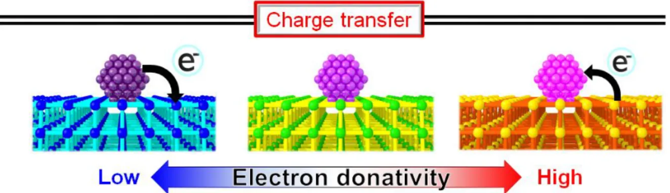
As I mentioned above, an electronic states of metal NPs put an influence on their catalytic activity in various catalytic reactions. The electronic states of NPs can be modifed by an electronic intercation between the metal NPs and a support. Then, the manner of the electronic intercation shoud depend on the support properties of charge transfer. In case that the MOFs are applied as the catalytic support, I expect that the direction and strength of the electronic interaction can be controlled by the MOFs for the following reasons.
It is probable that the amount of charge transfer strongly depends on a work function, i.e.
ionization potential of MOFs, which is a parameter of electronic enegy level of the support. In general, a valence band or HOMO (the highest occupied molecular orbital) of metal oxides consitituing of O2p orbital and C2p oribal, respectively. Such orbitals are often too low to donate a charge to metal NPs and it is not easy to change the energy level of their conduction band or LUMO (the lowest unoccupied molecular orbital).
In MOFs, the top of the valence band consists of the HOMO of ligand in the MOFs and the energy state can be controled by chemical modification of the ligands of MOFs. For reasons mentioned above, I expect that a novel highly active with an intentional charge transfer to (or from) metal NPs catalyst can be obtained by using MOF as a catalytic support as shown in Figure 1-12.
Figure 1-12. Scheme of electronic interaction between metal NPs and MOFs
15
II. Substrate adsorption by MOFs
As I also mentioned above, on various heterogeneous catalysis using metal NPs loading catalysts, some researchers reported that the substrate adsorption by a catalytic support can affect on the catalytic activity of loaded metal NPs. There are some reports attempting to explore an optimization condition of the substrate adsorption on a catalytic support, which maximizes the catalytic activity of the loaded metal NPs although the understanding of the effect is not sufficiently deepen because the type of traditional supports such as metal oxide and carbon materials which show high adsorption ability for the reactant is not so many. Meanwhile, MOFs have specific adsorption abilities originating from its high surface area and porous structure. The specific adsorption abilities can be varied by replacing or modifying the ligand of the MOF. The features of MOF are suitable as a research target to examine an influence on a catalytic activity of the substrate adsorption by a catalytic support. A systematic investigation of the effect from MOF’s adsorption ability on the catalytic activity will clearify that how much the adsorption ability is suitable for the reaction (as shown in Figure 1-13).
Figure 1-13. Scheme of a substrate adsorption by MOF
For these reasons, in this thesis, I aim to conduct systematic investigations on the support effect deriving from the substrate adsorption of a catalytic support by applying several types of MOFs which have different adsorption abilities. To perform such systematic investigation, I prepare several types of MOFs with metal NPs and characterize their physical properties and
16
catalytic activities. In addition, to complete the systematic investigation precisely, i.e. to purely compare an effect from MOF by suppressing any effects from things that are not a property of the support, I produce the catalysts including metal NPs with the same amounts and average diameters.
I described about the preparation fulfilling such a condition in chapter 2. In chapter 3 and 4,
“I. electronic interaction between metal NPs and MOFs” and “II. substrate adsorption by MOFs”
were described, respectively.
1-4. References
1. Zhang, S.; Duan, X.; Ye, L.; Lin, H.; Xie, Z.; Yuan, Y.; Catal. Today 2013, 215, 260–266.
2. Mars, P.; van Krevelen D. W. Chemi. Eng. Sci. 1954, 3, 41–59.
3. Chatterjee, D.; Deutschmann, O.; Warnatz, J. Faraday Discussions 2001, 119, 371–384.
4. (a) Springer, T. E.; Wilson, M. S.; Gottesfeld, S. J. Electrochem. Soc. 1993, 140, 3513–
3526. (b) Shiju, N. R.; Guliants, V. V., Appl. Catal. A-Gen., 2009, 356, 1–17.
5. Campelo, J. M.; Luna, D.; Luque, R.; Marinas, J. M.; Romero, A. A. ChemSusChem, 2009, 2, 18–45.
6. Daniel, M. C.; Astruc, D. Chem. Rev. 2004, 104, 293–346.
7. Link, S.; El-Sayed, M. A. Int. Rev. Phys. Chem. 2000, 19, 409–453.
8. Park, K. W.; Choi, J. H.; Kwon, B. K.; Lee, S. A.; Sung, Y. E.; Ha, H. Y.; Hong, S. A.;
Kim, H.; Wieckowski, A. J. Phys. Chem. B 2002. 106, 1869–1877.
9. (a) Burch, R. Phys. Chem. Chem. Phys. 2006, 8, 5483–5495, (b) Gonzalez, I. D.; Navarro, R. M.; Wen, W.; Marinkovic, N.; Rodriguez, J. A.; Rosa, F.; Fierro, J. L. G. Catal. Today 2010, 149, 372–379.
10. (a) Zhai, Y.; Pierre, D.; Si, R.; Deng, W.; Ferrin, P.; Nilekar, A. U.; Peng, G.; Herron, J.
A.; Bell, D. C.; Saltsburg, H.; Mavrikakis, M.; Flytzani-Stephanopoulos, M. Science 2010, 329, 1633– 1636, (b) Jacobs, G.; Williams, L.; Graham, U.; Thomas, G. A.;
17
Sparks, D. E.; Davis, B. H. Appl. Catal., A 2003, 252, 107– 118, (c) Bunluesin, T.;
Gorte, R. J.; Graham, G. W. Appl. Catal., B 1998, 15, 107– 114, (d) Phatak, A. A.;
Koryabkina, N.; Rai, S.; Ratts, J. L.; Ruettlinger, W.; Farruto, R. J.; Blau, G. E.; Delgass, W. N.; Ribeiro, F. H. Catal. Today 2007, 123, 224– 234, (e) Lida, H.; Kondo, K.;
Igarashi, A. Catal. Commun. 2006, 7, 240– 244, (f) Panagiotopoulou, P.;
Christodoulakis, A.; Kondarides, D. I.; Boghosian, S. J. Catal. 2006, 240, 114– 125, (g) Kalamaras, C. M.; Gonzalez, I. D.; Navarro, R. M.; Fierro, J. L. G.; Efstathiou, A. M. J.
Phys. Chem. C 2011, 115, 11595– 11610. (h) Gonzalez, I. D.; Navarro, R. M.; Wen, W.;
Marinkovic, N.; Rodriguez, J. A.; Rosa, F.; Fierro, J. L. G. Catal. Today 2010, 149, 372–
379
11. Bruix, A.; Rodriguez, J. A.; Ramirez, P. J.; Senanayake, S. D.; Evans, J.; Park, J. B.;
Stacchiola, D.; Liu, P.; Hrbek, J.; illas, F. J. Am. Chem. Soc. 2012, 134, 89688974.
12. Sharif, M. J.; Kitano, M.; Inoue, Y.; Niwa, Y.; Abe, H.; Yokoyama, T.; Hara, M.; Hosono, H. J. Phys. Chem. C 2015. 119, 11725–11731.
13. Kitano, M.; Kanbara, S.; Inoue, Y.; Kuganathan, N.; Sushko, P. V.; Yokoyama, T.; Hara, M.; Hosono, H. Nat. Commun. 2015, 6, 6731.
14. Widmann, D.; Behm, R. J. Accounts Chem. Res. 2014, 47, 740–749.
15. Rachmady, W.; Vannice, M. A. J. Catal. 2000, 192, 322–334.
16. Carrettin, S.; McMorn, P.; Johnston, P.; Griffin, K.; Kiely, C. J.; Hutchings, G. J. Phys.
Chem. Chem. Phys. 2003, 5, 1329-1336.
17. Mu, Y.; Liang, H.; Hu, J.; Jiang, Li; Wan, L. J. Phys. Chem. B 2005. 109, 22212–22216.
18. Li, Y.; Wang, H.; Xie, L.; Liang, Y.; Hong, G.; Dai, H. J. Am. Chem. Soc. 2011, 133, 7296–
7299.
19. Deng, H.; Grunder, S.; Cordova, K. E.; Valente, C.; Furukawa, H.; Hmadeh, M.; Gándara, F.; Whalley, A. C.; Liu, Z.; Asahina, S.; Kazumori, H.; O’Keeffe, M.; Terasaki, O.;
Stoddart, J. F.; Yaghi, O. M. Science 2012, 336, 1018–1023.
18
20. Herm, Z. R.; Wiers, B. M.; Mason, J. A.; van Baten, J. M.; Hudson, M. R.; Zajdel, P.;
Brown, C. M.; Masciocchi, N.; Krishna, R.; Long, J. R. Science 2013, 340, 960–964.
21. Horcajada, P.; Chalati, T.; Serre, C.; Gillet, B.; Sebrie, C.; Baati, T.; Eubank, J. F.;
Heurtaux, D.; Clayette, P.; Kreuz, C.; Chang, J. S.; Hwang, Y. K.; Marsaud, V.; Bories, P.
N.; Cynober, L.; Gil, S.; Férey, G.; Couvreur, P.; Gref, R. Nature Mater. 2010, 9, 172–178.
22. Kurmoo, M. Chem. Soc. Rev. 2009, 38, 1353–1379.
23. Sadakiyo, M.; Yamada, T.; Kitagawa, H. J. Am. Chem. Soc. 2014, 136, 13166–13169.
24. Wang, P.; Zhao, J.; Li, X.; Yang, Y.; Yang, Q.; Li, C. Chem. Commun. 2013, 49, 3330–
3332.
25. Zhou, J.; Wang, P.; Wang, C.; Goh, Y. T.; Fang, Z.; Messersmith, P. B.; Duan, H. ACS Nano 2015, 9, 6951–6960.
19
Chapter 2. Preparation of Pt/MOFs
2-1. Introduction
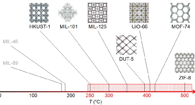
The temperatures of thermal decomposition of MOFs are much different depending on its type.1 In this research, I need to find out MOFs which have an enough thermal tolerance to apply the MOFs as catalytic supports to thermal heterogeneous catalysis. Considering about the reaction conditions of CO oxidation reaction in chapter 3 and acetic acid hydrogenation reaction in chapter 4, the MOFs as support must retain its structure even at >250 °C. I chose and synthesized 12 types of MOFs (DUT-5,2 HKUST-1,3 MIL-101,4 MIL-121,5 MIL-125,6 MIL- 125-NH2,7 Mg-MOF-74,8 Zn-MOF-74,9 UiO-66,10 UiO-66-NH2,11 ZIF-812 and ZIF-6713) as candidates showing high stability over 250 °C under inert gas although a detailed stability examination under the actual reaction conditions is needed later. Figure 2-1 shows the reported temperature of thermal decomposition of the MOFs under N2 flow condition as an example of the way of the choice, including MIL-4614 and MIL-8915 which are not chosen by the lack of thermal stability.
Figure 2-1. An example of temperature of thermal decomposition of MOFs
20
Upon a selection to metal species of the NP catalyst, I chose Pt NPs because the Pt NPs can be highly stable and active catalyst and is very commonly used for various catalytic reactions, as we can see from that Pt catalyst is used for polymer electrolyte membrane fuel cells.16 In addition, there are reports that Pt NPs have catalytic activities for the aimed catalytic reactions, i.e. CO oxidation17 and acetic acid hydrogenation18 reaction. Then, the compositions of Pt NPs on various MOFs (Pt/MOFs) were prepared as the catalysts.
For the preparation of the composition of Pt NPs on supports, chemical reagents are usually used as a metal source, solvent, reductive reagent and protective reagent in conventional methods (e.g. impregnation19, preipitation20, sol-gel21, chemical vapor deposition22, chemical reduction method23 and so on). For example, a metal salts as the metal source and the water or organic solvents are used in the chemical reduction method. A reductive reagent such as NaBH4
is also frequently added to precipitate the metal NPs. With using the liquid chemical reagents, the possibility of unexpected effect from such chemicals cannot be rule out nevertheless I aim to do precise examinations of an interaction between the Pt NPs and MOF supports. A preparation condition with no room for doubt about influences from any chemical reagents is preferable for this research.Moreover, to do a systematic comparison of the property of MOF supports, the similar-sized NPs should be loaded on different types of MOFs with almost the same loading amount. Therefore, I chose an arc plasma deposition method for the preparation of Pt/MOFs. In this method, the metal NPs were loaded by a plasma irradiation in a vacuum chamber without any chemical reagents. No use of any chemical reagents can ensure that the loaded Pt NPs directly contact with the MOFs. The resulting samples were named as Pt/MIL- 125-NH2, Pt/UiO-66-NH2, Pt/HKUST-1, Pt/MIL-101, Pt/Zn-MOF-74, Pt/Mg-MOF-74 and Pt/MIL-121. To compare with one of the best catalyst support among basic metal oxides, TiO2
(Degussa, P-25) and γ-Al2O3 (Aerosil, fumed silica) were also chosen as catalytic support loaded Pt NPs by the same method (Pt/TiO2 and Pt/Al2O3).
21
2-2. Experimental
2-2-1. Preparation of MOF supports
Synthesis of DUT-5 ({Al(OH)(bpdc)}∞ (H2bpdc = 2,2′- bipyridyl-5,5′-dicarboxylic acid)) Al(NO3)3·9H2O (1.88 g, 5.0 mmol) and H2bpdc (0.8 g, 3.3 mmol) were dissolved in 120 ml of DMF. After simply sonication, the solution was placed in Teflon-lined autoclaves and heated at 180 °C for 24 h. Then, white solid was precipitated and washed with MeOH. The white powder was dried at 120 °C under vacuum for 6h.
Synthesis of HKUST-1 ({Cu3(btc)2}∞ (H3btc = trimesic acid))
Cu(NO3)2·3H2O (20.8 g, 86.0 mmol) was dissolved in 500 ml of mixed solvent (DMF : EtOH : distilled water = 1 : 1 : 1). Trimesic acid (10.0 g, 47.6 mmol) was also dissolved in the mixture and sonicated for 15 minute. The solution was heated at 85 °C for 20 h. Then, blue solid was precipitated in the solution. The blue precipitate was separated through decantation. After washing with DMF, the blue precipitate was immersed in chloroform for four days. This operation was replenished by three times. The blue precipitate was separated by filtration and washed with MeOH and distilled water. To dry the powder, it was heated at 160 °C in vacuo.
To remove unreacted chemicals and solvent, reflux using MeOH was conducted for a day. After that, the sample was moved into DMF. The mixture was kept at 70 °C for 26 h. After separation by centrifugation, the resultant was washed with MeOH and head at 160 °C under vacuum until dryness.
Synthesis of MIL-101 ({Cr3(OH)(H2O)2O(bdc)3}∞ (H2bdc = terephthalic acid))
Cr(NO3)3·9H2O (2.0 g, 5.0 mmol), terephthalic acid (0.83 g, 5.0 mmol) and 20 ml of deionized water were mixed and stirred for 15 min. The mixture was placed in Teflon-lined autoclaves and heated at 218 °C for 18 h. The resulting green precipitate was centrifuged and washed with DMF, water and acetone. Finally, the resultant was dried at 70 °C under vacuum.
22
Synthesis of MIL-121 ({Al(OH)(btec)}∞ (H4btec = pyromellitic acid))
Al(NO3)3·9H2O (29.7 g, 79.2 mmol) and pyromellitic acid (13.4 g, 52.8 mmol) were dissolved in 80 ml of H2O. This solution was heated at 210 °C for 24 h in Teflon-lined autoclaves. After replacing the water, the precipitate was heated at 80 °C for 12 h. This washing process was repeated two times more. Then, the precipitate was filtered and dried in atmosphere.
Synthesis of MIL-125 ({Ti8O8(OH)4(bdc)6}∞ (H2bdc = terephthalic acid))
Titanium (IV) isopropoxide (0.78 ml, 2.6 mmol), terephthalic acid (1.50g, 9.0 mmol) were added in mixture of 22.5 ml of DMF and 3.0 ml of ethanol. The mixture was stirred until dissolved. Then, it was heated at 130 °C for 15h in Teflon-lined autoclaves. The precipitate was separated by filtration and washed with MeOH and Acetone. At last, the resulting white powder was heated at 70 °C under vacuum.
Synthesis of MIL-125-NH2 ({Ti8O8(OH)4(bdc-NH2)6}∞ (H2bdc-NH2 = 2- aminoterephthalic acid))
Titanium (IV) isopropoxide (3.12 ml, 10.4 mmol) and 2-aminoterephthalic acid (6.0 g, 36.0 mmol) were dissolved in mixed solvent of 22.5 ml DMF and 3.0 ml MeOH. After sonication for 15 minute, this solution was heated at 130 °C for 15 h in Teflon-lined autoclaves. The precipitate was washed with MeOH and Acetone. It was filtered and evacuated to dryness at 70°C for 12 h under vacuum.
Synthesis of Zn-MOF-74 ({Zn2(dobdc)}∞ (H4dobdc = 2,5-dihydroxyterephthalic acid)) Zn(NO3)2·6H2O (22.6 g, 76.0 mmol) was dissolved in 1000 ml DMF. 2,5- dihydroxyterephthalic acid (5.00 g, 26.0 mmol) was also dissolved in the mixture and sonicated 10 minute. Then, to this solution, 50 ml of distilled water was added and heated at 100 °C for 20 h. After that, yellowish-brown solid was precipitated in the mixture. The precipitate was
23
separated by decantation process and rinsed with DMF and immersed in MeOH for five days.
This operation was repeated two times. The yellowish-brown precipitate was separated by filtration. After washing with MeOH and distilled water, it was refluxed in MeOH for 30 hour.
The sample was dried in air after separation by centrifugation.
Synthesis of Mg-MOF-74 ({Mg2(dobdc)}∞ (H4dobdc = 2,5-dihydroxyterephthalic acid)) Mg(NO3)2·6H2O (31.4 g, 122 mmol) was dissolved in mixed solvent consist of 198 ml of distilled water, 198 ml of EtOH and 2970 ml of DMF. 2,5-dihydroxyterephthalic acid (7.39 g, 37.3 mmol) was dissolved in the mixture and sonicated for 15 min. The solution was heated at 125 °C for 21 h. Then, yellowish-brown solid was precipitated in the solution. The yellowish- brown precipitate was separated by decantation and immersed in MeOH for two days. This operation was repeated five times. The sample was separated by filtration and dried at 250 °C for 6 h under vacuum.
Synthesis of UiO-66 ({Zr6O4(OH)4(bdc)6}∞ (H2bdc = terephthalic acid))
Zr (IV) Cl4 (1.66 g, 7.1 mmol) and terephthalic acid (1.16 g, 7.0 mmol) were dissolved in 30 ml of DMF and 0.8 ml of 35% HCL. To completely dissolve these ingredients, the mixture was heated and stirred at 60 °C. After completely dissolution, it was put in Teflon-lined autoclaves and heated at 220 °C for 17h. Resulting white precipitate was separated by filtration and washed with DMF and MeOH. After that, the white powder was dried at 180 °C under vacuum overnight.
Synthesis of UiO-66-NH2 ({Zr6O4(OH)4(bdc-NH2)6}∞ (H2bdc-NH2 = 2-aminoterephthalic acid))
Zr (IV) Cl4 (11.52 g, 49.43 mmol) was dissolved in 2880 ml of DMF by sonication for 15 minute. 2-aminoterephthalic acid (8.928 g, 49.29 mmol) was mixed into the solution. After
24
sonication for 15 minute, the mixture was heated at 120 °C for 24 h. Then, yellow solid was precipitated in the solution. The yellow precipitate was separated using centrifugation. After that, it was washed with DMF and MeOH. The precipitate was heated at 160 °C in vacuo until dryness.
Synthesis of ZIF-8 ({Zn(mIm)2}∞ (HmIm = 2-methylimidazole))
Zn(NO3)2·6H2O (9.70 g, 33.3 mmol) and 2-methylimidazole (22.00 g, 266.6 mmol) were dissolved in 1000 ml of MeOH. After simply sonication, the mixture was stayed for 24 h without stirring. The precipitate was separated by filtration.
Synthesis of ZIF-67 ({Co(mIm)2}∞ (HmIm = 2-methylimidazole)
Co(NO3)2·6H2O (9.70 g, 33.3 mmol) and 2-methylimidazole (22.00 g, 266.6 mmol) were dissolved in 1000 ml of MeOH. After simply sonication, the mixture was stayed for 24 h without stirring. The precipitate was separated by filtration.
25
2-2-2. Preparation and characterization of Pt/MOFs
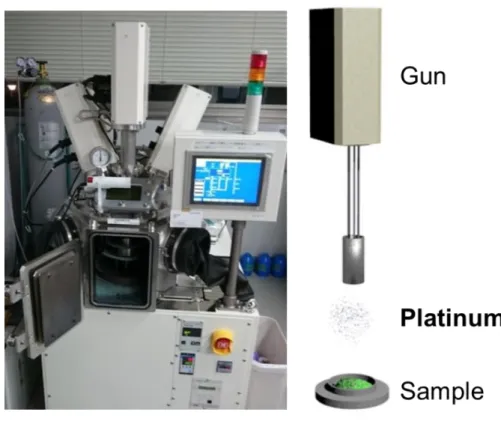
Deposition of Pt NPs using arc plasma deposition method
Pt/MOFs (Pt/MIL-125-NH2, Pt/UiO-66-NH2, Pt/HKUST-1, Pt/MIL-101, Pt/Zn-MOF-74, Pt/Mg-MOF-74 and Pt/MIL-121), Pt/TiO2 and Pt/Al2O3 were prepared by the arc plasma deposition method. A simple description of this method is shown in Figure 2-2. The arc plasma deposition method was conducted using an arc plasma gun (ULVAC ADP-3P-N2) with a Pt rod as a metal source. 1.8–7.3g of support was putted in a pot, which was placed in a vacuum chamber, and continuously stirred by stir bars at 30 rpm. The pot was kept at 18 °C by a water- cooling unit during the experiment. Thousands of arc plasma discharges at the Pt rod were irradiated to the support at 1Hz. The applied voltage for the discharges was 140 V.
Figure 2-2. A photo of arc plasma gun and scheme of this method
Characterization of Pt NPs loaded MOFs
X-ray powder diffraction (XRPD) measurements were conducted by using synchrotron radiation ( = 1.080 Å) at BL44B2 beamline belongs to RIKEN Materials Science or X-ray
26
radiation of Cu-K (Rigaku SmartLab diffractometer). When the samples were measured at the synchrotron, they were sealed in capillaries after drying at 150 °C under vacuum for over 6h.
N2 adsorption isotherms were measured by BELSORP-MAX (BEL Japan, Inc.) at 77K. All measured samples were heated at 150°C under vacuum to dry before the measurements.
The distribution and diameters of Pt NPs were observed using scanning transmission electron microscopy (STEM). In addition, some samples were analyzed by STEM coupled with energy dispersive X-ray spectrometry (STEM-EDS). The STEM and STEM-EDS observations were performed by JEM-ARM200F in the Ultramicroscopy Research Center of Kyusyu university. The loading amounts of Pt were analyzed by inductively coupled plasma- atomic emission spectroscopy (ICP-AES) using iCAP6300 (Thermo-Fisher). Before the measurements, all Pt NPs must be completely dissolved in aqueous solution. To perform it, all samples (20-60 mg) were completely dissolved using about 12 ml of aqua regia, in some cases, the mixture was heated at 80 °C to perform it.
2-3. Results and Discussion
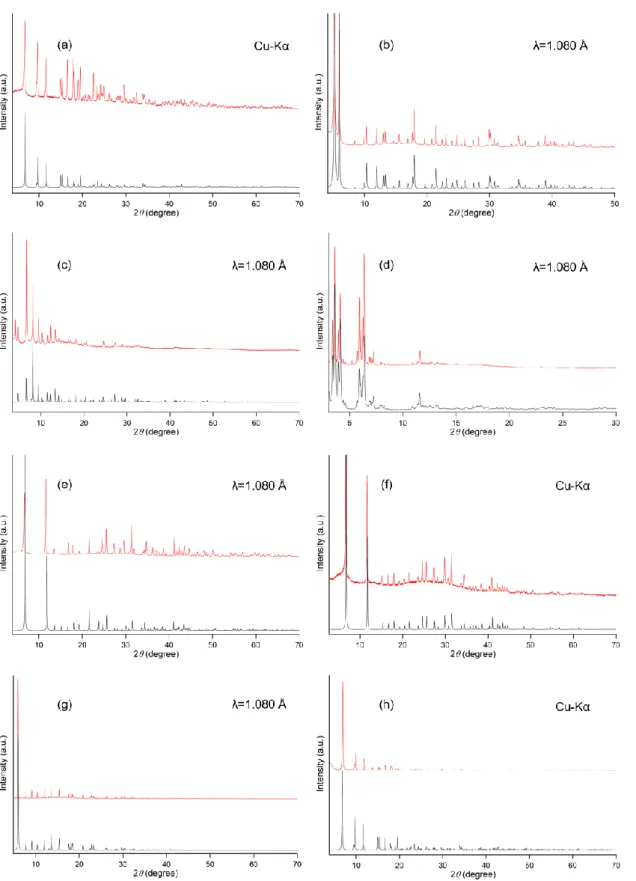
I synthesized the twelve kinds of MOFs (DUT-5, HKUST-1, MIL-101, MIL-121, MIL-125, MIL-125-NH2, Mg-MOF-74, Zn-MOF-74, UiO-66, UiO-66-NH2, ZIF-8 and ZIF-67) as catalytic supports. XRD patterns of the prepared MOFs are shown in Figure 2-3a and 3b. From comparison of XRD patterns of as prepared samples and simulation patterns calculated from each crystallographic information, I confirmed that the diffraction peak positions almost matched with the simulated patterns and there is no an unidentified peak. Note that an intensity of XRD peak of MOFs are varied easily by an influence from coordination status of H2O molecules in atmosphere. From these results, I confirmed that the syntheses were performed correctly.
27
Figure 2-3a. XRPD patterns (λ=1.080Å) of (a) MIL-125-NH2, (b) UiO-66-NH2, (c) HKUST- 1, (d) MIL-101, (e) Zn-MOF-74, (f) Mg-MOF-74, (g) MIL-121 and (h) MIL-125. Red and black lines indicate as prepared and simulation patterns, respectively.
28
Figure 2-3b. XRPD patterns (λ=1.080Å) of (a) UiO-66, (b) ZIF-8, (c) ZIF-67 and (d) DUT-5.
Red and black lines indicate as prepared and simulation patterns, respectively.
In addition, N2 adsorption measurements at 77K were performed to characterize the porous structures of the prepared MOF samples. Using the obtained N2 adsorption isotherms as shown in Figure 2-4, a standard BET (Brunauer-Emmett-Teller) analysis was conducted to calculate their BET surface area. The calculated BET surface area and reported values of them were summarized in Table 2-1. I confirmed that there is no large difference between the obtained and reported values. This results suggest that the obtained MOFs have their original porous structures.
29
Figure 2-4a. N2 adsorption isotherms of (a) MIL-125-NH2, (b) UiO-66-NH2, (c) HKUST-1, (d) MIL-101, (e) Zn-MOF-74, (f) Mg-MOF-74, (g) MIL-121 and (h) MIL-125.
30
Figure 2-4b. N2 adsorption isotherms of (a) UiO-66, (b) ZIF-8, (c) ZIF-67 and (d) DUT-5.
Table 2-1. Reported and calculated values of BET surface area (cm3 g-1) of MOFs, respectively.
Then, Pt NPs were deposited on the prepared MOFs and some metal oxides (TiO2 and Al2O3, described later) using arc plasma deposition method. By some reasons mentioned later, I
31
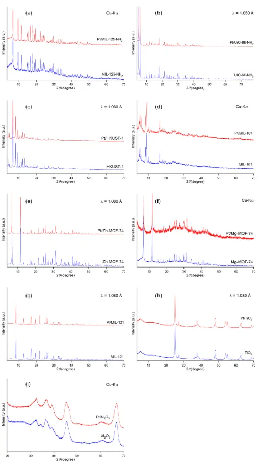
specifically chose the seven types of MOFs (MIL-125-NH2, UiO-66-NH2, HKUST-1, MIL- 101, Zn-MOF-74, Mg-MOF-74 and MIL-121) as catalytic supports to be conducted the Pt loading method. TiO2 and Al2O3 were modified by applying Pt NPs in the same method as references. The prepared catalysts were named as Pt/MIL-125-NH2, Pt/UiO-66-NH2, Pt/HKUST-1, Pt/MIL-101, Pt/Zn-MOF-74, Pt/Mg-MOF-74, Pt/MIL-121, Pt/TiO2 and Pt/Al2O3, respectively. XRD measurement of the obtained Pt/MOFs were performed to characterize their structures. From comparison with the XRD patterns, I confirmed that the XRD patterns of MOFs remain even after the arc plasma deposition experiments as shown in Figure 2-5. This result indicates that the structures of MOFs weren’t be destroyed by the Pt NPs loading. Note that the XRD peaks from Pt were not detected in all samples because the loaded Pt NPs were too small in this condition.
32
Figure 2-5. XRD patterns of (a) Pt/MIL-125-NH2, (b) Pt/UiO-66-NH2, (c) Pt/HKUST-1, (d) Pt/MIL-101, (e) Pt/Zn-MOF-74, (f) Pt/Mg-MOF-74, (g) Pt/MIL-121, (h) Pt/TiO2 and (i) Pt/Al2O3 before and after the arc plasma deposition experiments.
33
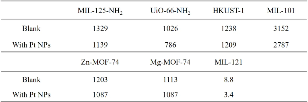
N2 adsorption experiments were also conducted with the prepared Pt/MOFs. The obtained isotherms of the Pt/MOFs and the MOF supports are shown in Figure 2-6. From comparisons of the calculated BET surface area of these samples before and after the Pt NPs deposition, I found that the BET surface areas were slightly decreased after the Pt loading as summarized in Table 2-2. The slight decrease indicates that the small parts of surface areas of the MOFs are occupied by the deposited Pt NPs. Such decrease also indicates that the arc plasma deposition method does not destroy the structures of MOFs. Note that the very small surface area of MIL- 121 is as reported.5
34
Figure 2-6. N2 adsorption isotherms of (a) MIL-125-NH2, (b) UiO-66-NH2, (c) HKUST-1, (d) MIL-101, (e) Zn-MOF-74, (f) Mg-MOF-74 and (g) MIL-121 before (black) and after (red) the arc plasma deposition method.
35
Table 2-2. Calculated BET surface areas of MOFs and Pt/MOFs.
Next, the loaded Pt NPs were characterized by STEM observation and ICP measurements. To see how the Pt NPs were loaded, STEM images of the Pt/MOFs are shown in Figure 2-5 which indicates that loaded Pt NPs were homogeneously distributed on every support. Note that the black dots in Figure 2-7 were recognized as Pt NPs, which was judged as right by EDS analysis (described later). The particle size distributions of Pt NPs on MOFs were calculated by counting 200 particles in the STEM image. The graphs of the analyzed diameter distributions of Pt NPs are also shown as insets of Figure 2-5. The average diameters of Pt NPs in Pt/MIL-125-NH2, Pt/UiO-66-NH2, Pt/HKUST-1, Pt/MIL-101, Pt/Zn-MOF-74, Pt/Mg-MOF-74, Pt/MIL-121 were estimated to be 2.0 ± 0.3, 1.9 ± 0.2, 1.9 ± 0.3, 2.0 ± 0.2, 1.9 ± 0.2, 2.0 ± 0.3 and 2.0 ± 0.2 nm, respectively, indicating that the loaded Pt NPs are characterized with similar diameters of approximately 2 nm. The used support amount, number of plasma shot, amount and diameter of Pt NPs were summarized in Table 2-3.
36
Figure 2-7. STEM images of (a) MIL-125-NH2, (b) Pt/UiO-66-NH2, (c) Pt/HKUST-1, (d) Pt/MIL-101, (e) Pt/Zn-MOF-74, (f) Pt/Mg-MOF-74, (g) Pt/MIL-121 and (h) Pt/TiO2.
37
Table 2-3. Support amount, number of plasma shot, amount and diameter of Pt NPs resulting from arc plasma deposition operation.
In addition, some samples were analyzed by STEM-EDS experiments as shown in Figure 2- 8. In every sample, EDS signals from Pt were detected at the edge of MOF crystals, suggesting that Pt NPs are loaded on surface of the MOF crystals, not in inner of crystals. Note that the EDS analysis of MIL-121 could not be completed because the crystals of MIL-121 were easily broken by the irradiation of an electron beam of EDS analysis. Furthermore, EDS-line analyses also strongly probe this conclusion. The result of the analysis was shown in Figure 2-9.
Comparison with the distribution of EDS signals from Pt and center metal of the MOFs revealed that most of Pt NPs loaded onto MOFs by arc plasma method are deposited on the surface of the support materials. From the result, I found that arc plasma deposition method can homogeneously prepare metal NPs with almost the same diameters and loading amounts (about 2.0 nm and 0.5 wt%), even using different types of MOFs and metal oxide, without applying any chemical reagents.32,33
38
Figure 2-8. (left) STEM images and (right) STEM–EDS maps of (a) Pt/MIL-125-NH2, (b) Pt/UiO-66-NH2, (c) Pt/HKUST-1, (d) Pt/MIL-101, (e) Pt/Zn-MOF-74and (f) Pt/Mg-MOF-74.
As shown upper right of the right figures, green and blue dots represent EDS signals from each atom of Pt NPs (Pt-M) and central metals of MOFs (Ti-K, Zr-K, Cu-K, Cr-K, Zn-L and Mg-K), respectively.
39
Figure 2-9. (left) EDS mapping images and (right) obtained spectra of EDS-line analysis of (a) Pt/MIL-125-NH2, (b) Pt/UiO-66-NH2, (c) Pt/HKUST-1, (d) Pt/MIL-101, (e) Pt/Zn-MOF-74 and (f) Pt/Mg-MOF-74. The white arrow indicates the measured line of line analysis.
2-4. Conclusions
In conclusion, I prepared 12 types of MOFs (DUT-5, HKUST-1, MIL-101, MIL-121, MIL- 125, MIL-125-NH2, Mg-MOF-74, Zn-MOF-74, UiO-66, UiO-66-NH2, ZIF-8 and ZIF-67) as candidates which are reported its high thermal stability. To load Pt NPs on the MOFs with no use of any reagents, the arc plasma deposition method was performed. XRD measurements proved that the structures of MOFs are not destroyed by the Pt deposition. By STEM observation and ICP measurement, it is clarified that I succeeded in homogeneously loading of Pt NPs with almost the same diameters and amounts (about 2.0 nm and 0.5 wt%) on the various
40
types of MOFs. STEM-EDS analysis give us an information about the distribution of Pt NPs on the MOFs. This is the first report of homogeneously loading of the same metal NPs on different types of MOFs.24,25 In other words, there is no difference among the Pt/MOFs except the types of MOF supports because the sizes and amounts of Pt NPs are almost the same. Then, a difference in a catalytic performance of these catalyst is assignable to the effect from the MOF support without doubt. Therefore, catalytic experiments using these composites make us possible to purely evaluate an effect from the type of support.
2-5. References
1. Howarth, A. J.; Liu, Y.; Li, P.; Li, Z.; Wang, T. C.; Hupp. J. T.; Farha, O. K. Nat. Rev. Mat., 2016, 1, 15018.
2. Senkovska, I.; Hoffmann, F.; Froeba, M.; Getzschmann, J.; Boehlmann, W.; Kaskel, S., Micropor. Mesopor. Mat., 2009, 122, 93–98.
3. Chui, S. S.-Y.; Lo, S. M.-F.; Charmant, J. P. H.; Orpen, A. G.; Williams, I. D. Science 1999, 283, 1148–1150.
4. Ferey, G; Mellot-Draznieks, C; Serre, C; Millange, F; Dutour, J; Surble, S; Margiolaki, I., Science, 2005, 309, 2040–2042.
5. Volkringer, C.; Loiseau, T.; Guillou, N.; Ferey, G.; Haouas, M.; Taulelle, F.; Elkaim, E.;
Stock, N. Inorg. Chem. 2010, 49, 9852–9862.
6. Dan-Hardi, M.; Serre, C.; Frot, T.; Rozes, L.; Maurin, G.; Sanchez, C.; Ferey, G., J. Am.
Chem. Soc. 2009, 131, 10857-10859.
7. Zlotea, C.; Phanon, D.; Mazaj, M.; Heurtaux, D.; Guillerm, V.; Serre, C.; Horcajada, P.;
Devic, T.; Magnier, E.; Cuevas, F.; Férey, G.; Llewellyn, P. L.; Latroche, M. Dalton Transactions, 2011, 40, 4879–4881.
8. Dietzel, P. D. C.; Blom, R.; Fjellvåg, H. Eur. J. Inorg. Chem. 2008, 23, 3624–3632.
9. Rosi, N. L.; Kim, J.; Eddaoudi, M.; Chen, B.; O’Keeffe, M.; Yaghi, O. M. J. Am. Chem.
41
Soc. 2005, 127, 1504–1518.
10. Cavka, J. H.; Jakobsen, S.; Olsbye, U.; Guillou, N.; Lamberti, C.; Bordiga, S.; Lillerud, K.
P. J. Am. Chem. Soc. 2008, 130, 13850–13851.
11. Kandiah, M.; Nilsen, M. H.; Usseglio, S.; Jakobsen, S.; Olsbye, U.; Tilset, M.; Larabi, C.;
Quadrelli, E. A.; Bonino, F.; Lillerud, K. P. Chem. Mater. 2010, 22, 6632–6640.
12. Park, K. S.; Ni Z.; Cote, A. P.; Choi, J. Y.; Huang, R.; Uribe-Romo, F. J.; Chae, H. K.;
O'Keeffe, M.; Yaghi, O. M. PNAS, 2006, 103, 10186–10191.
13. Banerjee, R.; Phan1, A.; Wang, B.; Knobler, C.; Furukawa, H.; O'Keeffe, M.; Yaghi, O. M.
Science, 2008, 319, 939–943.
14. Sassoye, C.; Marrot, J.; Loiseau, T.; Ferey, G. Chem. Mater., 2012, 14, 1340–1347.
15. Serre, C.; Millange, F.; Surble, S.; Ferey, G. Angew. Chem. Int., 2004, 46, 6285–6289.
16. Ohma, A.; Shinohara, K.; Iiyama, A.; Yoshida, T.; Daimaru, A., ECS Trans. 2011, 41, 775–784.
17. Chua, Y. P. G.; Gunasooriya, G. T. K. K.; Saeys, M.; Seebauer, E. G. J. Catal. 2014, 311, 306–313.
18. Rachmady, W.; Vannice, M. A. J. Catal. 2000, 192, 322–334.
19. Medina-Mendoza, A. K.; Cortés-Jácome, M. A.; Toledo-Antonio, J. A.; Angeles-Chávez, C.; López-Salinas, E.; Cuauhtémoc-López, I.; C. Barrera, M.; Escobar, J.; Navarrete, J.;
Hernández, I.;, Appl. Cat. B., 2011, 106, 14–25.
20. Petcharoen, K.; Sirivat, A., Mat. Sci. Eng., B-Adv., 2012, 177, 421–427.
21. S. V, Ingale; P. B, Wagh; D. Bandyopadhyay; I. K, Singh; R. Tewari; S. C, Gupta, Conf.
Ser.: Mater. Sci. Eng. 2015, 73, 012076.
22. Hermannsdörfer, J.; Friedrich, M.; Miyajima, M.; Albuquerque, R. Q.; Kümmel, S.; Kempe, R., Angew. Chem., Int. Ed., 2012, 51, 11473.
23. Kim, S.; Song, K.; Kim, M.; Jang, I.; Oh, S-G., J. Phys. Chem. Solids, 2013, 74, 524–529.
24. Chen, Y.; Mu, X.; Lester, E.; Wuac, T., Pro. Nat. Sci-Mater., 2018, 28, 584–589.
42
25. Bhattacharjee, S.; Chen, C.; Ahn, W-S.; RSC Adv., 2014, 4, 52500–52525.
26. Choi, I.; Jung, Y. E.; Yoo, S. J.; Kim, H-J.; Lee. C. Y.; Jang, J. H., J. Electrochem. Sci.
Technol., 2017, 8, 61–68.
27. Bao, Z.; Yu, L.; Ren, Q.; Lu, X.; Deng, S. J. Colloid Interf. Sci., 2011, 353, 549–556.
28. Xiao, J-D.; Han, L.; Luo, J.; Yu, S-H.; Jiang, H-L., Angew. Chem. Int., 2017, 57, 1103–
1107.
29. Cmarik, G. E.; Kim, M.; Cohen, S. M.; Walton, K. S. Langmuir, 2012, 44, 15606–15613.
30. Yang, H.; He, X-W.; Wang, F.; Kang, Y.; Zhang, J., J. Mater. Chem., 2012, 22, 21849–
21851.
31. Gotthardt, M. A.; Grosjean, S.; Brunner, T. S.; Kotzel, J.; Ganzler, A. M.; Wolf, S.; Brase, S.; Kleist, W. Dalton Trans., 2015, 44, 16802–16809.
32. (a) Sadakiyo, M.; Yoshimaru, S.; Kasai, H.; Kato, K.; Takata, M.; Yamauchi, M.
Chem. Commun., 2016, 52, 8385–8388. (b) Sadakiyo, M.; Heima, M.; Yamamoto, T.; Matsumura, S.; Matsuura, M.; Sugimoto, S.; Kato, K.; Takata, M.; Yamauchi, M. Dalton Trans., 2015, 44, 15764–15768.
33. Yoshimaru, S.; Sadakiyo, M.; Staykov, A.; Kato, K.; Yamauchi, M. Chem. Commun., 2017, 53, 6720–6723.
43
Chapter 3. Charge transfer effect on Pt/MOFs
3-1. Introduction
In this chapter, I report about one of the unveiled support effects of MOFs, i.e., an electronic interaction between the loaded metal NPs and MOF supports. In conventional material such as oxide-supported metal catalysts, the support strongly affects the catalytic activity of metal NPs through charge-transfer1 which accelerates catalytic reaction on the heterointerface between metal NPs and oxides.2 In particular, some researchers recently reported that electronic interactions between metal NPs and an oxide support can control catalytic activities; this is referred to as the EMSI.3 However, such oxides are unsuitable for electron donation to metal NPs because the valence band level of the oxide support, which is mainly composed of O 2p orbitals, is too low to increase the electron density on the metal NP surface. This limits the modification range of the electronic states of supported metal NPs, whereas the electron-rich environments in metal NPs are also important in some cases.4 Considering that the valence orbitals of MOFs are mainly derived from organic ligands, the energetic states of MOFs are potentially tunable through the ligand design. Therefore, I believe that MOF supports provide a great opportunity to achieve a wider range of control of catalytic activities in heterogeneous catalysis through the electronic interaction with metal NPs.
As a model reaction of this investigation, CO oxidation reaction in gas phase was selected.
This reaction is known as a reaction with a highly sensitivity to electronic state of loaded Pt NPs.5 Note that Pt/MIL-101, Pt/MIL-121 and Pt/MIL-125 were not included in this investigation because of some reasons such as its catalytic activity of the bare support and an overlapping in XPS signal from Pt and the center metals, which disturbs the accurate evaluation.
Then, the 4 types of Pt/MOFs (Pt/Zn-MOF-74, Pt/Mg-MOF-74, Pt/HKUST-1 and Pt/UiO-66- NH2) were selected as catalysts in this work.
44
Detailed studies on the electronic states of the Pt/MOF series were carried out using X-ray photoelectron spectroscopy (XPS), ultraviolet photoelectron spectroscopy (UPS) and density functional theory (DFT) calculations, which indicated that the electronic interaction between Pt NPs and a MOF support, i.e., electronic interaction.
To examine how the electronic states of the Pt NPs influence catalytic reactions, performances of the Pt/MOFs for a CO oxidation reaction were evaluated. The CO oxidation reaction was conducted in a fixed-bed flow reactor, loading catalyst powder that includes the same amount of Pt. I found that the catalytic activity on the reaction apparently differ according to the types of the MOF supports. Moreover, the order of the reaction temperature is the same as that observed in the electronic states of Pt NPs.
Through these experiments, I show the first report on systematic investigation of support effect of MOF, i.e., electronic interaction.
3-2. Experimental
3-2-1. Evaluation of electronic properties of Pt/MOFs.
X-ray photoelectron spectroscopy (XPS)
Electronic states of loaded Pt NPs were estimated by XPS measurements with ULVAC-PHI PHI 5000 VersaProbe II (Al-K, h = 1486.6 eV). Binding energies obtained by XPS were calibrated with C1s spectra of carbon tape on the sample holder at 284.6 eV. In particular, I focused on electrons of 4f7/2 (70–73.5 eV) and 4f5/2 (73.5–78 eV), which are known for appearing significant spectrum as XPS spectra of Pt NPs. Note that unidentified broad peaks around 75–78 eV were necessary to be used for the fitting of HKUST-1 data, which is probably attributable to Cu3p peaks.6 Obtained spectra were analyzed by least squares method under the assumption that the Pt NPs include Pt0, Pt2+ and Pt4+.
45
Ultraviolet photoelectron spectroscopy (UPS)
UPS measurement was also performed using the ULVAC-PHI PHI 5000 VersaProbe II (He I, h = 21.2 eV) with a bias (–6.0 or –11.0 V) applied to the sample holder. As mentioned below, to estimate working function of samples from UPS spectra, I have to detect “zero momentum energy = Ecutoff”. However, the value of energy is usually too low to be detected, this time too.
Then, the applied bias (–6.0 or –11.0 V) helps us detect it by accelerating photoelectrons (i.e.
increasing the energy of detected photoelectrons). Note that, the zero momentum energy represent an energy of photoelectron which barely beyond a barrier of ionization energy, among the photoelectrons generated from UV irradiation. As shown in Figure 3-1, to ensure electronic conduction of the surface of our samples and a sample holder, fixation of samples was performed by not carbontape but metal mask and washer. Gold wire (25 m) was also used to avoid charge-up on the surfaces of the samples. Ionization potentials (EI) obtained by the UPS were estimated by the following equation.
EI = h ( HeI: 21.2 eV) – (Ecutoff – EHOMO)
Here, EHOMO represents a momentum energy of photoelectron emitted from the top level of valence band. Simple scheme explaining the relationship among them are shown in Figure 3-2.
Figure 3-1a. Photos of (left) mask, (center) washer and (right) sample holder used for UPS measurement.
46
Figure 3-1b. A photo of the sample holder with all parts (with HKUST-1).
Figure 3-2. Theory of calculation of an ionization energy from UPS spectrum.
47
Density functional theory calculation
Calculations in this study were performed with plane-wave density functional theory implemented in the Vienna ab initio simulation package.7–10 The Perdew–Burke–Ernzerhof exchange-correlation functional was employed using projector-augmented wave pseudopotentials. I used the graphical visualization software package VESTA to analyze and visualize the optimized geometries11 as shown in Figure 3-3. Spin-polarized calculations were performed with 400 eV cutoff energy. Geometry optimization was performed and all atomic coordinates and cell parameters were fully relaxed. The geometry optimization was performed with k-point sampling at the gamma points. Monkhorst–Pack k-point sampling was used to estimate the local potential of the investigated metal–organic frameworks (MOFs). The k-point mesh for Mg-MOF-74 was 2 2 8, for Zn-MOF-74 2 2 8, for UiO-66-NH2 2 2 2, and for HKUST-1 2 2 2. The ionization potentials of the MOFs were calculated as a difference between the vacuum level and the top level of valence band of the MOFs. The value of the vacuum level was taken at the center of the void or pore of each MOF structure. For Mg-MOF- 74 and Zn-MOF-74, this point was selected with coordinates of 0.0, 0.0, 0.5 relative to the cell parameters. For HKUST-1 and UiO-66-NH2, this point was selected with coordinates of 0.5, 0.5, 0.5 relative to the cell parameters as shown in Figure 3-4. This approach has been reported in the literature.12