A STUDY ON THE DISASTER INFORMATION COLLECTION SUPPORT SYSTEM, INCORPORATING INFORMATION AND COMMUNICATION
TECHNOLOGY
A. Shibayama
1, Y. Hisada
2, M. Mirakami
3, M. Endo
4, S. Zama
4, O. Takizawa
5, M. Hosokawa
6and T. Ichii
71
Expert Researcher, National Institute of Information and Communications Technology, Tokyo. Japan
2
Professor, Dept. of Architecture, The Kogakuin University, Tokyo, Japan
3
Associate Professor, Dept. of Architecture, The Kogakuin University, Tokyo, Japan
4
Researcher, National Research Institute of Fire and Disaster, Tokyo, Japan
5
Group Leader, National Institute of Information and Communications Technology, Tokyo, Japan
6
General Manager, Fire and Disaster Management Agency of the Ministry of Internal Affairs and Communications, Tokyo, Japan
7
Sales Executive, Autonomy Corp., Tokyo, Japan Email: [email protected]
ABSTRACT:
We have developed a support system to facilitate the rapid and effective collection of disaster information, and we have conducted operational experiments to test the system in Tokyo, Japan. We have named this system the Disaster Information Collection Support System (DICSS); it incorporates the Geographic Information System (GIS) and Information and Communication Technology (ICT). We have added additional functions to the DICSS in order to increase the efficiency of investigation, such as an information sharing function using ad hoc network technology, an information collecting function using a middle-distance laser rangefinder, and an information sharing function using a radio frequency identification (RFID) tag. This improved system is a simple and user-friendly GIS specialized for collecting disaster information; it has been designed so that anyone can use it. It can change the specific data under investigation to accommodate the requirements of each individual situation, from quick inspections to rapid assessments of the safety of buildings to detailed investigations for academic purposes. When a public communications network is rendered nonfunctional by a disaster, the system is capable of securing communication between terminals by ad hoc network. It can collect information on the damage caused to a remote location from an elevated position by using laser rangefinder binoculars. We applied this system to an experiment conducted in Tokyo, Japan and confirmed its validity and effectiveness.
KEYWORDS:
Information Collection, Disaster Inspection, GIS, Laser Rangefinder, Ad Hoc Network, GPS
1. INTRODUCTION
Since the 1995 Kobe earthquake, the national and local governments of Japan have developed systems for
information collection during earthquakes, such as the Disaster Information System (DIS) developed by the
cabinet office of the government of Japan, the REaltime Assessment of earthquake Disaster in Yokohama
(READY) of the city of Yokohama, and the estimated seismic intensity map of the Japan Meteorological
Agency (JMA). However, it is important to keep in mind that the actual damage caused by an earthquake could
be different from the estimated damage. If we rely on only the estimated information, the emergency response
may be inadequate. On the other hand, the estimated information can be useful in locating the most severely
affected areas at the initial stage of the damage investigation. With all of this in mind, we have proposed a
real-time system for collecting earthquake damage information (Shibayama et al., 2002 [1]). In this paper, we
will introduce the details of this novel system and explain the results of the field experiments undertaken to check the effectiveness of the proposed system.
2. THE DISASTER INFORMATION COLLECTION SUPPORT SYSTEM, INCORPORATING INFORMATION AND COMMUNICATION TECHNOLOGY
2.1. The Main Features of the System
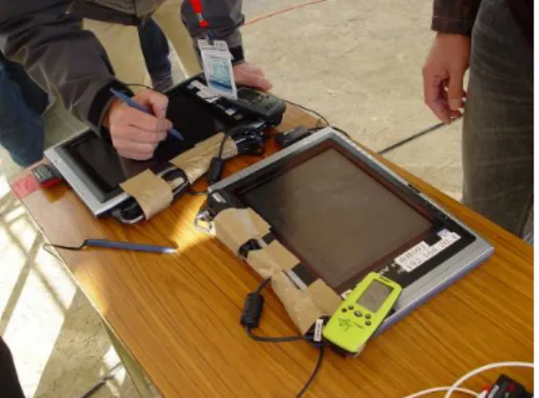
As shown in Figure 1 and Photo 1, we have developed the Disaster Information Collection Support System (DICSS) to efficiently perform the collection, transmission, and consolidation of actual data pertaining to areas affected by a disaster utilizing Information and Communication Technology (ICT) equipment (e.g., tablet PC, Global Positioning System (GPS), ad hoc network, and laser rangefinder). The DICSS was developed based on two existing systems: an efficient system for acquiring earthquake damage information by Shibayama et al.
(2004) [2] and a disaster information collection terminal developed by Zama et al. (2001) [3]. Additional functions to increase the efficiency of the investigation were also added to the system, such as an information sharing function using an ad hoc network, an information collecting function using a middle-distance laser rangefinder, an information sharing function using a radio frequency identification (RFID) tag, and a simulation coordination function.
The main features of the proposed system are as follows:
・ This system is a simple and user-friendly GIS specially designed to collect damage information;
・The input to this system can be changed depending on the purpose of the investigation.
・The system imports data in standard vector and raster data formats.
・ The system can be accessed using a personal computer, without the need for any special equipment.
・The combined system can determine a worker’s present position using the connected GPS.
・ It facilitates the collection of data on the damage sustained in a remote location from an elevated position by using laser rangefinder binoculars.
・ When a public communications network is rendered nonfunctional by a disaster, it can secure communication between terminals by ad hoc network.
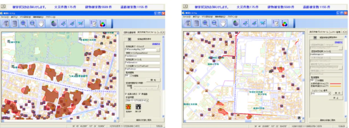
Figure 1 Main window of the system. Photo 1 Example of extended system (Tablet PC).
2.2. The Configuration and Function of the System 2.2.1 The system configuration
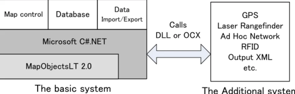
As shown in Figure 2, the DICSS consists of a basic system and any additional systems. The basic system was
developed in the GIS engine of ESRI MapObjects LT 2.0 and Microsoft C#.NET, which have all the tools
necessary for creating and maintaining a GIS, and an interface designed for indoor and outdoor use. The basic
system can be used to manipulate the map display, display data using classifications, pan and zoom through
multiple map layers, manage a database of collected data, import external data, and export collected data.
Additional functions can be added to the basic system to increase the efficiency of the investigation, such as an investigator's navigation function using GPS, an information sharing function using ad hoc communication, an information collecting function using the middle-distance laser rangefinder, and an information sharing function using an RFID tag. It is possible to develop these additional systems using Microsoft C#.NET or Microsoft VisualBasic.NET, and the user can use some other system to develop the additional systems.
Figure 2 Concept chart of the system configuration.
2.2.2 The system equipment
The DICSS software license is available free of cost and is open to public use. In addition, common personal computers can be used to run it—no special equipment is required. Thus, it is possible to collect damage information by assembling many volunteers for data collection following an earthquake. The personal computer used for data input can be a desktop, a laptop, or a tablet (see Photo 2) depending on the purpose and situation.
For example, a laptop PC or tablet PC is appropriate in the field, whereas a desktop PC is more appropriate in an office. The minimum requirements of the current system are compatibility with a Pentium or higher CPU, a 16-bit high color screen adapter with a resolution of 1024 × 768 or higher, and a keyboard or other input device (mouse, tablet, etc.). This system can be run on Microsoft Windows 2000, Windows XP, or Windows Vista. The minimum RAM size is 256 MB for Windows 2000, 512 MB for Windows XP, and 1 GB for Windows Vista.
The minimum hard-disk space required to run the system is 200 MB, although it could be more, depending on the size of the digital maps used.
The DICSS configuration can be extended utilizing various peripheral ICT equipment such as a head-mounted display (HMD), GPS, digital communications terminals, or a digital camera. For example, a HMD frees a user’s hands to more efficiently input data (see Photo 2, right). The combination of GPS and the digital map can be used to navigate the target area—an extremely powerful tool for a person who is unfamiliar with the area.
Currently, the system is compatible with handheld GPS receivers; however, digital communications terminals such as cellular phones or wireless LANs can be used to transmit the data to the disaster headquarters.
Photo 2 Example of the system equipment. Left: Tablet PC. Right: Tablet PC and HMD.
2.2.3 Data import/export
As shown in Table 1, the DICSS is able to be used in various fields and is compatible with many different map
MapObjectsLT 2.0 Microsoft C#.NET
GPS Laser Rangefinder
Ad Hoc Network RFID Output XML
etc.
The basic system The Additional system
Map control Database Data
Import/ExportCalls
DLL or OCX
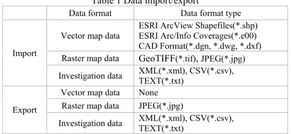
formats. This system supports formats for imported data in the form of vector maps ranging from standard GIS formats (ArcInfo coverages and ESRI shapefiles) to computer-aided design (CAD) formats (DXF, DWG, and DGN) and raster image formats (GeoTIFF and JPEG image compression). This system can export map images in raster image format (JPEG image compression).
The system uses ASCII data formats (XML, CSV, and TEXT) to input and output the investigated data. The investigation data that are output are compatible with various systems such as the disaster countermeasures system, the fire spread simulation system, and the evacuation simulation system.
Table 1 Data import/export
Data format Data format type
Import
Vector map data ESRI ArcView Shapefiles(*.shp) ESRI Arc/Info Coverages(*.e00) CAD Format(*.dgn, *.dwg, *.dxf) Raster map data GeoTIFF (*.tif) , JPEG(*.jpg) Investigation data XML(*.xml), CSV(*.csv),
TEXT(*.txt)
Export
Vector map data None Raster map data JPEG(*.jpg)
Investigation data XML(*.xml), CSV(*.csv), TEXT(*.txt)
2.2.4 The basic input data (location, properties, and damage grade) The basic input data of the DICSS are as follows:
a) Choice of damage type (building damage, road damage, or damage due to fire, selected from the side panel of the DICSS)
b) Locations of the damaged objects or areas (e.g., building, area, road) c) Information on the damaged objects or areas
Upon locating a damaged building, road, or area, we first choose the nature of damage; it can be a damaged building, a damaged road, or damage due to fire, each of which can be chosen from the side panel (see Figure 3, left). Second, we click on its location on the digital map. Third, we input information on the object’s properties.
After we choose the location, a pop-up window appears, from which one may choose the object type (see Figure 3, right), including construction material (e.g., wooden, steel, reinforced concrete or other), use of the building (e.g., residential, industrial, or commercial), damage grade (e.g., minor, major, or complete collapse), and casualties. Finally, after checking the confirmation window, which shows the all input items, we click the “yes”,
“no”, or “cancel” button.
Figure 3 Basic input data of the DICCS.
Left: Main window. Right: Input window for damage information.
Operation panel (input/output map data, zoom in/zoom out, navigation controls, information reference, etc.)
Mouse cursor position coordinate (Lat/Lon, X/Y) Input panel:
・Fire damage
・Building damage
・Road damage
・Information reference
・Information erasure
Damage information (e.g., fire damage)
2.2.5 The utilization of variably presented information
Using this system, we can change the input contents according to the requirements of the investigation. For example, we may require an immediate estimate of the overall damage in the affected areas after a large earthquake. In such a case, speed is more important than accuracy. On the other hand, inspecting the safety of damaged buildings requires us to carry out more detailed investigations. Accordingly, this system can provide various investigation menus ranging from simple to detailed. An academic investigation of structural damage is one example of a case that would require a detailed menu. For this purpose, we use the chart for describing building damage patterns proposed by Okada et al. (1999) [4] and Takai et al. (2001) [5].
2.3. The Information Collecting Function using a Middle-distance Laser Rangefinder
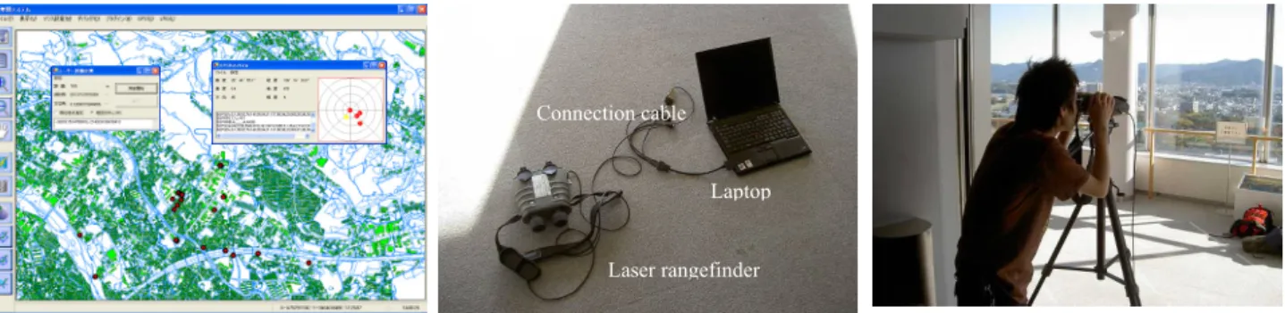
As shown in Figure 4, we have developed an additional function that uses a middle-distance laser rangefinder to collect information on fire and building damage from an elevated position (e.g., high-rise office building, steel tower, or other) or from a distance.
This system has the following features:
・ Ability to locate the area where the damage occurred from an elevated position or from a distance
・Ability to help ensure the investigator's safety from a fire or secondary disaster because of its capability of remote data collection
・Ability to collect information on damage over large areas in a short time
・ Ability to be used from a motorcycle, car, or helicopter
This additional function requires a hardware configuration that consists of a PC (e.g., Laptop or Tablet PC), the laser rangefinder, and a data cable. In this experiment, the laser rangefinder used a VECTOR IV from Vectronic that can measure range, azimuthal angle, and vertical angle. To use this system, input the locations of the origin form a GIS screen. The distance and the azimuthal angle from the starting point to the object are then measured using the laser rangefinder, and the object is displayed on the GIS screen. Finally, information on building and fire damage is input.
Figure 4 Laser rangefinder function
Left: Screen shot of the laser rangefinder function. Center: Example of the system configuration for the laser rangefinder function Right: Photograph of laser rangefinder in use.
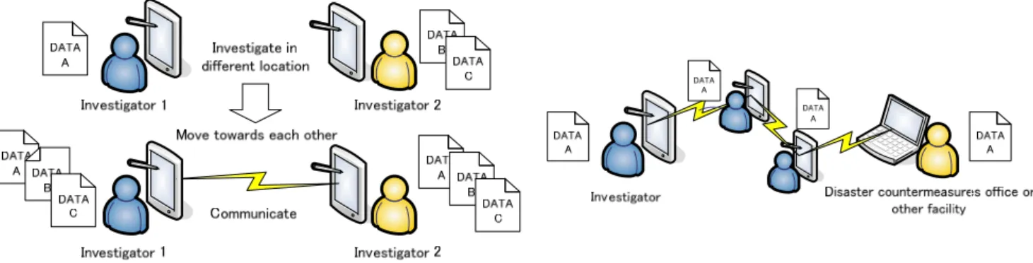
2.4. The Information Sharing Function using an Ad hoc Network
We developed two additional functions to accomplish information sharing using ad hoc network technology, a schematic of which is shown in Figure 5. One is an information sharing function and the other is an information communication function. The information sharing function shares the task of information collection between the terminals of the investigators, and the communication function transmits information to a remote terminal by the bucket brigade method. By using these functions, information sharing and transmission between the terminals are made possible in the case of a communication blackout during a large-scale earthquake.
Laser rangefinder Laptop Connection cable