Vol.6 (2021), pp. 9-14 -シンポジウム論文-
Thermal Analysis of Hybrid Structure of Power Generation and
Transmission Panel for SPS
†Takaya NAKAMURA*1‡, Naoki SEKIYA*2, Tatsuya YAMAGAMI*3, Hiroshi MIZOGUCHI*1, Koji TANAKA*4
We are studying and developing a hybrid structure that combines a thin film structure and a bulk structure in order to significantly reduce the mass of solar power satellite (SPS). One of the issues of realization for SPS is the enormous number of space transportations. Therefore, to reduce the number of space transportations, we're considering replacing some of the functions installed in the bulk structure with a lightweight and thin flexible structure. In addition, it is necessary to consider thermal deformation due to periodic changes in the amount of solar radiation from the viewpoint of microwave power transmission for the SPS. In this paper, we described the results of thermal analysis of hybrid structures that combines the thin film and the bulk structure for SPS. We evaluated the thermal deformation of hybrid structure. Also, we suggested hybrid structure that satisfies a requested value which is from the microwave power transmission of the tethered SPS.
Keywords:Solar Power Satellite, Reduction in the number of space transportations, Thermal deformation Nomenclature
c : Specific heat
Gain : Gain (10log10Pout Pin)
P : Power
PAE : Power-Added Efficiency
λ : Thermal conductivity
ρ : Density
Subscripts
C : Consumption
DC : Direct current
in : Radio frequency input
out : Radio frequency output
X : X-axis
Y : Y-axis
Z : Z-axis
1. Introduction
Solar Power Satellite (SPS) generates electrical energy using a large-scale solar array, and transmits generated energy using
microwaves to the ground. SPS is a sustainable energy system that can generate electricity with sunlight and without being affected by weather and day and night. SPS is expected the solution for serious problems of human society such as global warming and depletion of underground resources in the near future.
P. Glaser proposed the idea of SPS at first in 19681). In Japan, Japan Space Systems has been studying on the tethered SPS collaborated with JAXA and the universities2)-4).
A conceptional diagram of the tethered SPS is shown in Fig. 15). The main structure of the tethered SPS is a power generation and transmission panel consisting of many modules of the same specifications.
Fig. 1 Conceptional diagram of the tethered SPS5).
One of the issues for realizing the SPS is the transportation of the materials into the orbit. In the case of the tethered SPS, the area of the power generation and transmission is required a few km2, due to the energy output of GW class. To realize such a large-scale structure, many folded parts are transported into the orbit and deployed on the orbit. Deployed sub-structures will be connected in the orbit. In case of the tethered SPS, the number of transportations is 1,000 or more6). Other major problem is space transportation cost. Using current space transportation systems, † Presented online at the 6th Space Solar Power System
Symposium, December 4-5, 2020.
‡ Corresponding author: Takaya NAKAMURA. E-mail: [email protected]
*1 Tokyo University of Science, 2641, Yamazaki, Noda-shi, Chiba,
278-8610, Japan.
*2 Hosei University, 3-7-2, Kajinocho, Koganei-shi, Kanagawa,
184-8584, Japan.
*3 The Graduate University for Advanced Studies [SOKENDAI],
3-1-1 Yoshonodai, Chuo-ku, Sagamihara, Kanagawa, Japan.
*4 ISAS/JAXA Sagamihara Campus 3-1-1, Yoshinodai, Chuo-ku
Sagamihara-shi, Kanagawa, 252-5210, Japan. SSPSS
宇宙太陽発電 Vol.6 (2021), pp. 9-14
the cost of transporting 1 kg to an orbit is around 1 million yen7). Therefore, a cost reduction of space transportation is required to realize the SPS.
Our study purpose is the reduction in the number of transportations for SPS. In order to reduce the number of transportations, it is necessary the reduction of the mass of parts transported by rockets.
Fig. 2 Cross-section view of the power generation and transmission panel for the tethered SPS.
The power generation and transmission panel of the conventional tethered SPS has a bulk structure. Figure 2 is a schematic drawing of the power generation and transmission panel of the tethered SPS. Many functions will be installed in the power generation and transmission panel. Solar array will be attached on both surfaces of the panel. Antennas will be mounted on the power transmission side of the panel.
In case of solar array and antennas, these functions can be realized with thin film structure8). Therefore, when such thin film structure is used instead of bulk structure, the mass of the parts loaded on the rocket can be reduced. However, in the case of thin film, the thermal conductivity of the thin film is small, and it has a low natural frequency. Thus, RF circuits and power circuits that they contain heat elements need to be installed in the thickness parts (bulk structure). For these reasons, we’re studying and developing the deployable hybrid system combined with thin film and bulk structure.
One of the problems of power generation and transmission panel of the tethered SPS is a thermal deformation. The power generation and transmission panel will be deformed because there are temperature differences between the power generation side and the power transmission side due to a changing heat input from sun radiation. Because of that, efficiencies of the power generation and the transmission are decrease.
This study purpose is an evaluation of the thermal deformation of hybrid structure that combines the thin film structure and the bulk structure for SPS by the thermal analysis.
2. Heat transfer analysis
The power generation and transmission panel of the tethered SPS is formed by the structural unit with the size of 5 [m] × 0.5 [m]6). Each structural unit consists of 10 rigid electrical modules of 2,500 [mm] square size. Also, the target panel thickness is 20 [mm]9). Therefore, the area and thickness of each structure we considered made 500 [mm] x 500 [mm] size and around 20 [mm] thickness as same as rigid electrical module.
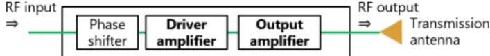
2.1 Phase control and power amplifier circuit In the case of the tethered SPS, phase and amplitude radiated from each antenna element will be controlled, and a high precision beam is made to send energy to the earth. Thus, there are many phase control and power amplifier circuit in the power generation and transmission panel. Figure 3 shows schematic drawing of the phase control and power amplifier circuit. The phase of the input microwave signal is controlled by the phase shifter, and the amplitude is amplified by the driver amplifier and output amplifier to transport electrical energy from the transmitting antenna to the ground. The driver amplifier and the output amplifier are heating elements in the circuit.
Fig. 3 Schematic drawing of the phase control and power amplifier circuit
Each 16 circuit is placed periodically in the tethered SPS9). A material of driver amplifier and output amplifier are gallium nitride and gallium arsenide. The size of each amplifier is 10 mm x 10 mm x 1 mm, and spacing between each amplifier is 10 mm. Thermal conductivity of each amplifier was referred from data sheet of each amplifier10)-11). Also, specific heat and density were referred from aluminum alloy (5052). Table 1 shows thermal properties of each amplifier.
Table 1 Thermal properties of each amplifier ρ [kg/m3] c [J/kg・K] λ [W/m・K] Driver amplifier 2.68 x 10³ 897 0.320 Output amplifier 1.05
According to the heating value of RF amplifiers, Power-Added Efficiency (PAE), Gain and Pout were defined as a
precondition. PAE is an index of amplifier efficiency. It shows how much DC power supplied to the amplifier is converted as RF power: PAE was given as Eq. (1).
𝑃𝑃𝑃𝑃𝑃𝑃 =𝑃𝑃𝑜𝑜𝑜𝑜𝑜𝑜− 𝑃𝑃𝑖𝑖𝑖𝑖
𝑃𝑃𝐷𝐷𝐷𝐷 ∗ 100 (1)
Also, in the case of the tethered SPS, it is considered that output power from one module is 55.5 W12). P
out from output
amplifier was defined that reference power divided 16 devices.
Pout from the driver amplifier was defined from Gain of output
amplifier. Table 2 shows the precondition values. From precondition values, Pin, PDC and PC were given as Eqs. (2)-(4). 𝑃𝑃𝑖𝑖𝑖𝑖= 𝑃𝑃𝑜𝑜𝑜𝑜𝑜𝑜 10𝐺𝐺𝐺𝐺𝑖𝑖𝑖𝑖10 (2) 𝑃𝑃𝐷𝐷𝐷𝐷=𝑃𝑃𝑜𝑜𝑜𝑜𝑜𝑜− 𝑃𝑃𝑖𝑖𝑖𝑖 𝑃𝑃𝑃𝑃𝑃𝑃 ∗ 100 (3) 𝑃𝑃𝐷𝐷= 𝑃𝑃𝐷𝐷𝐷𝐷− (𝑃𝑃𝑜𝑜𝑜𝑜𝑜𝑜− 𝑃𝑃𝑖𝑖𝑖𝑖) (4)
A result of calculation of Pc from the driver amplifier and the
output amplifier were 0.23 W and 0.79 W.
Table 2 Precondition values of each amplifier PAE [%] Gain [dB] Pout [W]
Driver amplifier 60 20 0.35
Output amplifier 80 10 3.5
2.2 Bulk structure Figure 4 shows a schematic drawing of a bulk structure. One side surface of the bulk structure was power transmission side, and transmission antenna elements and solar array were mounted on the surface. A phased-array antenna was considered for the tethered SPS. Thus, in the analysis model, there were 256 patch antenna elements. The opposite side of the bulk structure was power generation side, and solar array were mounted on the surface.
Fig. 4 Layout of each amplifier on circuit layer.
Fig. 5 Schematic drawing of the bulk structure.
In the bulk structure, an aluminum plate was placed between two honeycomb cores as the phase control and power amplifier circuit layer. As mentioned above, the driver amplifier and the power amplifier were placed on the circuit layer. Table 3 shows thermal material properties except for honeycomb core. Since honeycomb core is composed of many hexagonal cells, the pre-processing and post-processing become complicated in the finite element analysis. Therefore, the computation time becomes long, and a large amount of memory is required. For these reasons, it's more useful for thermal analysis to consider the thermal conductivity of honeycomb core as a 3D anisotropic composite material than to treat the thermal conductivity of each
component material separately 13). Table 4 shows the material properties of honeycomb core.
Table 3 Thermal material properties of bulk structure except for honeycomb core Material ρ [kg/m3] c [J/kg・K] λ [W/m・K] Copper* (Antenna) 8940 450 401 Glass14) (Dielectric) 2500 753 1 Polyimide15) (Solar array) 1420 1050 0.18 CFRP (Skin) X-axis 1700 1000 50 Y-axis 50 Z-axis 1.5 A5052* (Circuit layer) 2683 897 139
*Referred from a material property of Autodesk Inventor Nastran🄬🄬
Table 4 Thermal material properties of honeycomb core
ρ [mm] 36.8
c [mm] 900
𝜆𝜆𝑋𝑋 [W/m・k] 0.548
𝜆𝜆𝑌𝑌 [W/m・K] 0.822
𝜆𝜆𝑍𝑍 [W/m・K] 1.46
2.3 Thin film with frame structure Some functions that can be replaced from the bulk structure were mounted on a thin film structure. Figure 6 shows a thin film portion adopting a frame structure. Thin film with frame structure had three parts, power transmission side, frame structure and power generation side. The power transmission side included a power transmission antenna layer, a thin film photovoltaic cell and a flexible substrate. In the case of antenna layer, it was same as the bulk structure: there were 256 patch antenna elements. On the other side of the antenna elements layer, power amplifiers on the flexible substrates were included as a phase control and power amplifier circuit. The substrate material was assumed same as solar array. Power generation side had only the thin film photovoltaic cell. The frame structure was made of honeycomb core and width of frame was 20 mm.
宇宙太陽発電 Vol.6 (2021), pp. 9-14
The power generation and transmission panel of the tethered SPS is formed by the structural unit with the size of 5 m × 0.5 m. If a hybrid structure was defined alternated between the bulk structure and the thin film with frame structure, mass of hybrid structural unit become 54.6% than all bulk structural unit. Figure 7 shows schematic drawing of the hybrid structural unit. Black parts were the bulk structure and blue parts were thin film with frame structure.
Fig. 7 Schematic drawing of the hybrid structural unit. 2.4 Orbital thermal condition In this analysis, we assumed the same geosynchronous orbital thermal condition as the tethered SPS. Also, a solar beta angle was defined 0 deg because this analysis was a hot case. Table 5 shows the orbital thermal conditions which was high temperature version.
Number of cycles was 5. For this analysis, we used the values from the last cycle of stable temperature. Also, Table 6 shows optical properties of solar array and antenna (copper). An efficiency of solar array was assumed 35% and an input heat value to solar array from the sun radiation was difference between the solar absorption of solar array and efficiency of solar array9). Also, inside of thin film with frame structure was assumed black body paint.
Since thermal insulation assumed between the bulk structure and the thin film with frame structure, each structure was analyzed separately.
Table 5 Orbital thermal condition Orbital altitude [km] 36000 Solar beta angle [deg] 0 Solar radiation [W/m2]16) 1421
Albedo of the earth [-]17) 0.3
Earth infrared radiation [W/m2]17) 237
Table 6 Optical properties
Solar absorption [%] Emissivity [%]
Solar array9) 76 81
Antenna14) 28 15
Black body paint - 95
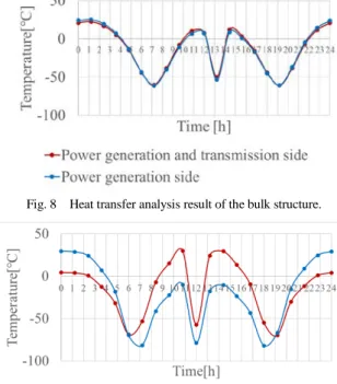
2.5 Analysis result In this heat transfer analysis, Thermal Desktop🄬🄬 was used. Figure 8 shows a result of the heat transfer analysis of the bulk structure. 0 on the horizontal axis is the time when the panel of the analysis model is perpendicular to the direction of sun radiation. Each temperature was an average of in-plane temperature. Max temperature difference between the power generation side and power generation and transmission side was around 13 hours on horizontal axis. In that time, the temperature difference between the power generation
side and the power generation and transmission side was 3.41 ℃.
Also, Fig. 9 shows a result of the heat transfer analysis of the thin film with frame structure. Each temperature was an average of in-plane temperature. Max temperature difference between the power generation side and power generation and transmission side around was 13 hours as same as the result of the bulk structure. In that time, the temperature difference between the power generation side and the power generation and transmission side was 42.1 [℃].
In a thermal stress analysis, these results when they were max temperature difference between faces were used.
Fig. 8 Heat transfer analysis result of the bulk structure.
Fig. 9 Heat transfer analysis result of the thin film with frame structure. 3. Thermal stress analysis
3.1 Conditions of each structure A thermal stress analysis models were constructed from main structural parts. Figure 10 shows schematic drawing of the thermal stress analysis model of the bulk structure and the thin film with frame structure. The thermal stress analysis models were same structure as the heat transfer analysis model except array antenna and each amplifier. This is because these parts do not affect the results of the thermal stress analysis.
In the thermal deformation analysis requires some
constraints. However, the SPS is floated in the outer space.
Therefore, a boundary condition was defined as a below to create the free-floating condition.
(ⅰ)The constraint to the translational direction in X, Y, and Z was created at O in Fig. 11. (O is an origin point of the model.) (ⅱ)The constraint to the translational direction in X and Z was created at A in Fig. 11. (A is a point along the Y-axis from O). (ⅲ)The constraint to the translational direction in Z was created at B in Fig. 11. (B is a point along the X-axis from O.)
The heat transfer analysis result of chapter 2 was applied for the thermal stress analysis. In the case of thin film with frame structure, average temperature of thin film on the frame structure and average temperature of thin film not on the frame structure were applied respectively. In this analysis, Autodesk Inventor Nastran🄬🄬 was used.
Fig. 10 Schematic drawing of the thermal stress analysis model of the bulk structure and the thin film with frame structure.
Fig. 11 Three constraint points as a free-floating condition in the analysis model.
3.2 Analysis results and discussion of each structure Figures 12 and 13 show contour diagrams of the thermal stress analysis result of each structure. The maximum out-of-plane deformation of bulk structure was 0.215 mm. Also, the maximum out-of-plane deformation of thin film with frame structure was 53.7 mm. As a requested value of the tethered SPS from microwave power transmission, one module out-of-plane deformation is one thirtieth of a power transmission wavelength9). In this analysis, the frequency and wavelength of the microwave for the power transmission are 5.8 GHz and around 51.7 mm, respectively. Therefore, allowable out-of-plane deformation of each structure was 1.72 mm9).
This analysis showed that out-of-plane deformation of the bulk structure was within the requested value of the tethered SPS from microwave power transmission. However, in the case of thin film with frame structure, the deformation value was exceeded from the allowable value. This cause of that was larger temperature difference between thin films than that of the bulk structure. Therefore, it’ll need more heat path between thin films to reduce temperature difference.
Also, in terms of structure, a proportional relationship between the length of one side thin film square and the amount of out-of-deformation was assumed. Then, this result was found out-of-plane deformation of the thin film with frame structure was within the requested value when 25 constraint points in the thin film structure were added and the area of the thin film divide separately about 83 mm×83 mm.
Fig. 12 Thermal stress analysis counter figure of the bulk structure.
Fig. 13 Thermal stress analysis counter figure of the thin film with frame structure.
4. Conclusion
We are considering the hybrid structure that combines the thin film and the bulk structure toward the realization of SPS. In this paper, thermal structural considerations of the hybrid structure for the SPS were described.
Mass of structural unit of the hybrid structure we proposed become 54.6% than all bulk structural unit. The results of this study were found that the out-of-plane thermal deformation of the bulk structure was within the requested value which is from the microwave power transmission of the tethered SPS. Also, this study found structural design the thin film with frame structure that satisfied the requested value.
References
1) P. E. Glaser: Power from the sun: Its future, Science, vol. 162 (1968), pp. 857-861.
2) S. Sasaki, K. Tanaka, S. Kawasaki, N. Shinohara, K. Higuchi, N. Okuizumi, K. Senda, K. Ishimura and the USEF SSPS Study Team: Conceptual Study of SSPS Demonstration Experiment, URSI Radio Science Bulletin, Issue: 310 (2004), pp. 9-24.
3) Shuji NAKAMURA, Kazuhiko MAEKAWA, Masao SATO and Kenji SASAKI and Shoichiro MIHARA: Microwave Transmission Experiment on the Ground for SSPS, Space Solar Power Systems, 1 (2016), pp.16-19.
4) Koji Tanaka: Cooperation between JAXA and universities towards Practical SPS, Proceedings of 60th Space Sciences and Technology Conference (2016), pp. 1-3.
5) JAXA Digital Archives, Conceptual example (The Space Solar Power Systems using microwave type), available from <http://jda.jaxa.jp/result.php?lang=j&id=8bb6ece10bfb5453f92c763 2e3bd8f0d>
6) Institute for Unmanned Space Experiment Free Flyer: Report on the Results of the 2006 Photovoltaic Power Generation Promotion Technology Survey, p.32, p.139.
7) Office of Space Policy, Cabinet Office, Government of Japan: Perspectives on Japan's Space Transportation System, available from <https://www8.cao.go.jp/space/plan/plan3/plan3.pdf>.
宇宙太陽発電 Vol.6 (2021), pp. 9-14 8) H. Nakanishi, H. Sakamoto, and OrigamiSat-1 Development Team:
Launch Report of Multi-Functional Deployable Membrane Structure Demonstrator, 3U CubeSat OrigamiSat-1, Proceedings of 63rd Space Sciences and Technology Conference (2019), pp. 1-6. 9) Institute for Unmanned Space Experiment Free Flyer: Report on the
Results of the 2006 Photovoltaic Power Generation Promotion Technology Survey: Separate Volume, pp. 21-22, pp. 38-48 p.51. 10) ANALOG DEVICES’s HMC406MS8G data sheet, available
from<https://www.mouser.jp/datasheet/2/609/hmc406-879288.pdf> 11) Wolfspeed (A CREE COMPANY)’s CGH40006 data sheet,
available from
<https://www.wolfspeed.com/downloads/dl/file/id/306/product/511/ cgh40006p.pdf>
12) Institute for Unmanned Space Experiment Free Flyer: Report on the Results of the 2007 Photovoltaic Power Generation Promotion Technology Survey, p.29.
13) A. Ohnishi, Thermal Design of Spacecraft, The University of Nagoya Press, Ehime (2014), pp. 43-46.
14) Daisuke Sato, Noboru Yamada, Member, IEEE, and Koji Tanaka: Thermal Design of Photovoltaic/Microwave Conversion Hybrid Panel for Space Solar Power System, IEEE JOURNAL OF PHOTOVOLTAICS, 7, NO.1 (2017), pp.374-382.
15) Polyimide Film 'APICAL'/ Typical Properties, available from <http://www.elecdiv.kaneka.co.jp/english/apical/poli_spec.html> 16) Saito, H., Yamakawa, H., Kobayashi, Y. and Mukai, T.: Mercury
Orbiter Mission with Chemical or Electric Propulsion, IAF-98-Q.2.04, 1998. (as cited in Keita FUKUZAWA, Akira OHNISHI and Yuji NAGASAKA: A Prediction of Thermal Radiation Properties of Multilayer Thermal Control Material Based upon Polyimide Film for Space Use, Journal of the Japan Society for Aeronautical and Space Sciences, 50 (2002), No. 579, pp. 129-134.)
17) Japan Aerospace Exploration Agency, DESIGN STANDARD SPACECRAFT THERMAL CONTROL SYSTEM, p.9 (2009).

![Table 3 Thermal material properties of bulk structure except for honeycomb core Material ρ [kg/m 3 ] c [J/kg・K] λ [W/m・K] Copper* (Antenna) 8940 450 401 Glass 14) (Dielectric) 2500 753 1 Polyimide 15) (Solar array) 1420 1050 0.18](https://thumb-ap.123doks.com/thumbv2/123deta/6837756.1169095/3.892.480.797.491.586/thermal-material-properties-structure-honeycomb-material-dielectric-polyimide.webp)